

Page 1
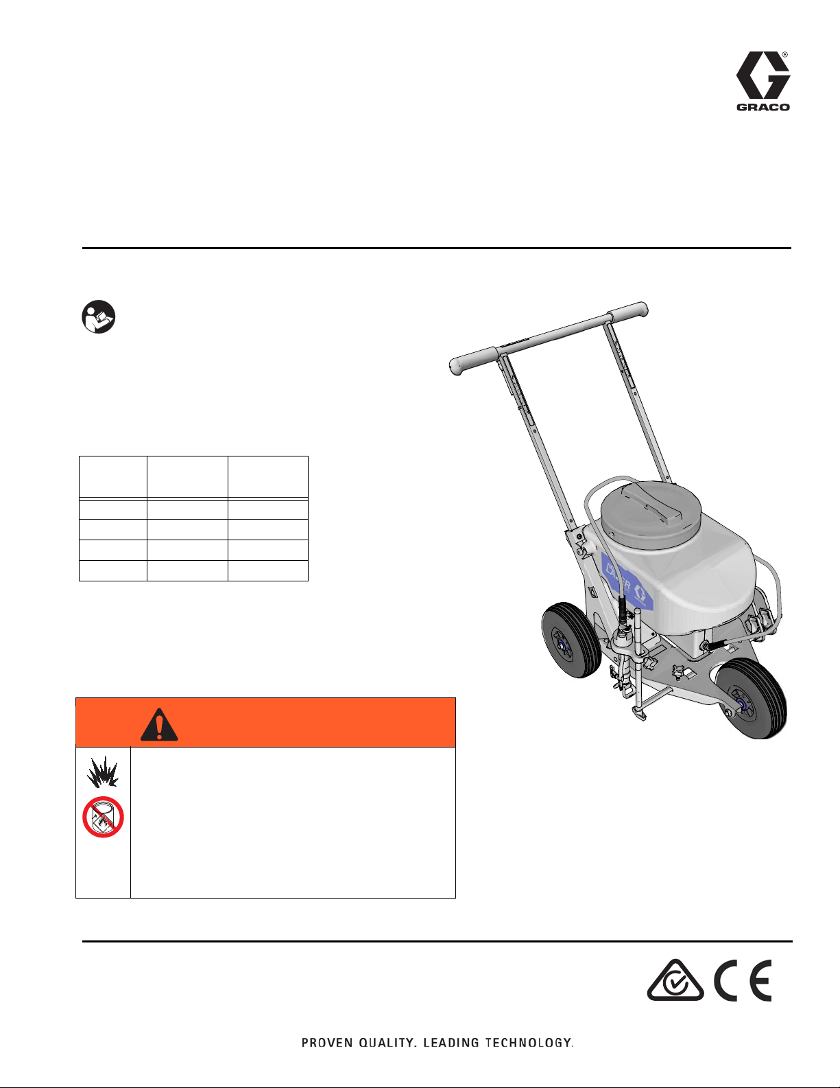
Operation - Repair - Parts
ti24682a
WARNING
Sports Field Marker
For field marking applications only
IMPORTANT SAFETY INSTRUCTIONS
Read all warnings and instructions in this manual
and on the unit. Be familiar with the controls and
the proper usage of the equipment.
Save these instructions.
All Models:
Maximum Working Pressure 1200 psi (8.3 MPa, 83 bar)
Model
24N950 120V B
24R023 240V B
24R370 240V B
24R371 120V/240V B
Charger
Voltage
Series
332119E
EN
FIRE AND EXPLOSION HAZARD
Solvent and paint fumes can ignite or explode.
• Use only water-based materials. Do not use
materials which state “FLAMMABLE” on the
packaging. For more information about your
material, request MSDS from distributor or
retailer.
• Do not spray or flush with flammable materials.
Page 2

Contents
Warnings . . . . . . . . . . . . . . . . . . . . . . . . . . . . . . . . . 3
Component Identification . . . . . . . . . . . . . . . . . . . . 6
Component Identification List . . . . . . . . . . . . . . . 7
Charging the Battery (Series A) . . . . . . . . . . . . . . . 8
Charger Indicator Lights . . . . . . . . . . . . . . . . . . . 8
Charging the Battery (Series B) . . . . . . . . . . . . . . . 9
Charger Indicator Lights . . . . . . . . . . . . . . . . . . . 9
Common Procedures . . . . . . . . . . . . . . . . . . . . . . 10
Prime/Spray Valve . . . . . . . . . . . . . . . . . . . . . . 10
Pressure Relief Procedure . . . . . . . . . . . . . . . . 10
Install Spray Tip/Guard
Assembly (if not installed) . . . . . . . . . . . . . . 10
Reversible Spray Tip . . . . . . . . . . . . . . . . . . . . . 11
Filter Removal / Cleaning . . . . . . . . . . . . . . . . . 11
Spraying . . . . . . . . . . . . . . . . . . . . . . . . . . . . . . 12
Emptying the Paint Hopper . . . . . . . . . . . . . . . . 12
Starting a New Job . . . . . . . . . . . . . . . . . . . . . . . . 13
Adjusting Line Width . . . . . . . . . . . . . . . . . . . . . 14
Shutdown and Cleaning . . . . . . . . . . . . . . . . . . . . 15
Flushing Field Marker . . . . . . . . . . . . . . . . . . . . 15
Optional Cleanup: . . . . . . . . . . . . . . . . . . . . . . . 16
Unclogging Spray Tip/Guard Assembly . . . . . . 17
Storage . . . . . . . . . . . . . . . . . . . . . . . . . . . . . . . . . . 18
Repair . . . . . . . . . . . . . . . . . . . . . . . . . . . . . . . . . . . 19
Tip Removal/Cleaning . . . . . . . . . . . . . . . . . . . . 19
CleanShot
Fuse Replacement . . . . . . . . . . . . . . . . . . . . . . 21
Battery Replacement . . . . . . . . . . . . . . . . . . . . . 22
Control Board Replacement . . . . . . . . . . . . . . . 24
Pump/Motor Removal . . . . . . . . . . . . . . . . . . . . 25
Troubleshooting . . . . . . . . . . . . . . . . . . . . . . . . . . . 28
Wiring Diagram . . . . . . . . . . . . . . . . . . . . . . . . . . . 30
Parts . . . . . . . . . . . . . . . . . . . . . . . . . . . . . . . . . . . . 31
Parts List . . . . . . . . . . . . . . . . . . . . . . . . . . . . . . 32
Parts . . . . . . . . . . . . . . . . . . . . . . . . . . . . . . . . . . . . 33
Parts List . . . . . . . . . . . . . . . . . . . . . . . . . . . . . . 34
Parts . . . . . . . . . . . . . . . . . . . . . . . . . . . . . . . . . . . . 35
Parts List . . . . . . . . . . . . . . . . . . . . . . . . . . . . . . 36
Technical Data . . . . . . . . . . . . . . . . . . . . . . . . . . . . 37
Graco Standard Warranty . . . . . . . . . . . . . . . . . . . 38
™
Cleaning (If applicable) . . . . . . . . . 19
2 332119E
Page 3

Warnings
WARNING
Warnings
The following warnings are for the setup, use, grounding, maintenance, and repair of this equipment. The exclamation point symbol alerts you to a general warning and the hazard symbols refer to procedure-specific risks. When
these symbols appear in the body of this manual or on warning labels, refer back to these Warnings. Product-specific
hazard symbols and warnings not covered in this section may appear throughout the body of this manual where
applicable.
SKIN INJECTION HAZARD
High-pressure spray is able to inject toxins into the body and cause serious bodily injury. In the event that
injection occurs, get immediate surgical treatment.
• Do not aim the gun at, or spray any person or animal.
• Keep hands and other body parts away from the discharge. For example, do not try to stop leaks with
any part of the body.
• Always use the nozzle tip guard. Do not spray without nozzle tip guard in place.
• Use Graco nozzle tips.
• Use caution when cleaning and changing nozzle tips. In the case where the nozzle tip clogs while
spraying, follow the Pressure Relief Procedure for turning off the unit and relieving the pressure
before removing the nozzle tip to clean.
• Equipment maintains pressure after power is shut off. Do not leave the equipment energized or
under pressure while unattended. Follow the Pressure Relief Procedure when the equipment is
unattended or not in use, and before servicing, cleaning, or removing parts.
• Check hoses and parts for signs of damage. Replace any damaged hoses or parts.
• This system is capable of producing 1200 psi (8.3 MPa, 83 bar). Use Graco replacement parts or
accessories that are rated a minimum of 1200 psi (8.3 MPa, 83 bar).
• Verify that all connections are secure before operating the unit.
• Know how to stop the unit and bleed pressure quickly. Be thoroughly familiar with the controls.
EQUIPMENT MISUSE HAZARD
Misuse can cause death or serious injury.
• Do not operate the unit when fatigued or under the influence of drugs or alcohol.
• Do not exceed the maximum working pressure or temperature rating of the lowest rated system
component. See Technical Data in all equipment manuals.
• Use fluids and solvents that are compatible with equipment wetted parts. See Technical Data in all
equipment manuals. Read fluid and solvent manufacturer’s warnings. For complete information
about your material, request MSDS from distributor or retailer.
• Do not leave the work area while equipment is energized or under pressure.
• Turn off all equipment and follow the Pressure Relief Procedure when equipment is not in use.
• Check equipment daily. Repair or replace worn or damaged parts immediately with genuine
manufacturer’s replacement parts only.
• Do not alter or modify equipment. Alterations or modifications may void agency approvals and create
safety hazards.
• Make sure all equipment is rated and approved for the environment in which you are using it.
• Use equipment only for its intended purpose. Call your distributor for information.
• Route hoses and cables away from traffic areas, sharp edges, moving parts, and hot surfaces.
• Do not kink or over bend hoses or use hoses to pull equipment.
• Keep children and animals away from work area.
• Comply with all applicable safety regulations.
332119E 3
Page 4

Warnings
WARNING
BATTERY HAZARD
The battery may leak, explode, cause burns, or cause an explosion if mishandled. Contents of an open
battery can cause severe irritation and/or chemical burns. If on skin, wash with soap and water. If in eyes,
flush with water for at least 15 minutes and get immediate medical attention.
• Only use the battery type specified for use with the equipment. See Technical Data.
• Replace battery only in a well-ventilated area and away from flammable or combustible materials,
including paints and solvents.
• When battery is not in use, keep it away from metal objects like keys, nails, screws or other metal
objects that can short circuit the battery terminals.
• Do not dispose of battery in fire or heat above 50 °C (122 °F). The battery is capable of exploding.
• Do not throw into fire.
• Charge only with Graco approved charger as listed in this manual.
• Do not expose battery to water or rain.
• Do not disassemble, crush, or penetrate the battery.
• Do not use or charge a battery that is cracked or damaged.
• Follow local ordinances and/or regulations for disposal.
CHARGER ELECTRIC SHOCK, FIRE AND EXPLOSION HAZARD
Improper setup or usage can cause electric shock, fire, and explosion.
• Charge only in a well-ventilated area and away from flammable or combustible materials, including
paints and solvents.
• Do not charge on a combustible or flammable surface.
• Do not leave battery unattended while charging.
• Immediately unplug charger and remove battery when charging is complete.
• Charge only Graco approved batteries listed in this manual; other batteries may burst.
• Use only in dry locations. Do not expose to water or rain.
• Do not use a charger that is cracked or damaged.
• If the supply cord is damaged, replace the charger or cord, depending on model.
• Never force the battery into the charger.
• When operating a charger outdoors, always provide a dry location and use an extension cord suit-
able for outdoor use.
• Disconnect the charger from the outlet before cleaning.
• Ensure that the outside surface of the battery is clean and dry before plugging into the charger.
• Do not attempt to charge non-rechargeable batteries.
• Do not disassemble the charger. Take charger to authorized service center when service or repair is
required.
PRESSURIZED ALUMINUM PARTS HAZARD
Use of fluids that are incompatible with aluminum in pressurized equipment can cause serious chemical
reaction and equipment rupture. Failure to follow this warning can result in death, serious injury, or property damage.
• Do not use 1,1,1-trichloroethane, methylene chloride, other halogenated hydrocarbon solvents or fluids containing such solvents.
• Do not use chlorine bleach.
• Many other fluids may contain chemicals that can react with aluminum. Contact your material sup-
plier for compatibility.
TOXIC FLUID OR FUMES HAZARD
Toxic fluids or fumes can cause serious injury or death if splashed in the eyes or on skin, inhaled, or
swallowed.
• Read MSDSs to know the specific hazards of the fluids you are using.
• Store hazardous fluid in approved containers, and dispose of it according to applicable guidelines.
4 332119E
Page 5

PERSONAL PROTECTIVE EQUIPMENT
WARNING
Wear appropriate protective equipment when in the work area to help prevent serious injury, including
eye injury, hearing loss, inhalation of toxic fumes, and burns. This protective equipment includes but is
not limited to:
• Protective eyewear, and hearing protection.
• Respirators, protective clothing, and gloves as recommended by the fluid and solvent manufacturer.
CALIFORNIA PROPOSITION 65
This product contains a chemical known to the State of California to cause cancer, birth defects or other
reproductive harm. Wash hands after handling.
Warnings
332119E 5
Page 6

Component Identification
Component Identification
6 332119E
Page 7

Component Identification List
Component Identification
A Spray Button
B Battery Shroud (battery inside)
C Battery Charger Connection Port
D Prime/Spray Valve
E Material Dispenser
FFilter
G Spray Tip/Guard Assembly
HPrime Hose
J Height Adjustment Mount
K Material Dispenser Height Adjustment Knob
L Material Dispenser Arm Adjustment Knob
M Spray Shields
N Motor Plug
P Spray Button Plug
R Paint Hopper Screen/Ball Knocker
S Tilt-N-Pour Paint Hopper
T Adjustable Handlebar Knob
W Paint Hopper Lid
332119E 7
Page 8

Charging the Battery (Series A)
A
ti20194a
ti2810a
12V
ti20190a
C
ti7949a
Charging the Battery (Series A)
4. Plug 12V charger jack into battery connection port
(C) on field marker.
Battery charger is for indoor use only. Do not expose
charger to rain or snow. Charge battery with
Graco-approved charger.
NOTE: Fully charge battery prior to first use.
1. Place field marker in a dry, well-ventilated area
away from flammable or combustible materials,
including paints and solvents.
2. Before charging, make sure spray button (A) is out
(OFF position).
5. When charging is complete, disconnect charger
from electrical outlet. Then disconnect charger from
battery connection port on field marker.
3. Plug charger into an electrical outlet.
Charger Indicator Lights
Appearance Description
RED Battery is being charged.
GREEN Charging is complete.
NOTE: Disconnect charger from field marker after battery is fully charged. Charge times will vary from 0 - 14 hours
depending on level of discharge.
NOTE: Green light on charger will be ON if:
• Charging is complete.
• Charger is NOT plugged into electrical outlet but is plugged into battery charger connection port on field marker.
• Charger is plugged into electrical outlet but is NOT plugged into battery charger connection port on field marker.
8 332119E
Page 9

Charging the Battery (Series B)
A
ti20194a
ti2810a
ti24686a
ti7949a
4. Plug 12V charger jack into battery connection port
on field marker.
Battery charger is for indoor use only. Do not expose
charger to rain or snow. Charge battery with
Graco-approved charger.
NOTE: Fully charge battery prior to first use.
1. Place field marker in a dry, well-ventilated area
away from flammable or combustible materials,
including paints and solvents.
2. Before charging, make sure spray button (A) is out
(OFF position).
5. When charging is complete, disconnect charger
from electrical outlet. Then disconnect charger from
battery connection port on field marker.
Charging the Battery (Series B)
3. Plug charger into an electrical outlet.
Charger Indicator Lights
Description Appearance
Power on with no battery connected Power LED is red
Desulfating
Charging
Charged/Float charging All four charging lights are on solid.
Reverse polarity All four charging lights flash.
Sleep mode. If the battery is fully charged or the charged is
connected to a fully charged battery the charger may go into
the sleep mode.
NOTE: Disconnect charger from field marker after battery is fully charged. Charge times will vary from 0 - 14 hours
depending on level of discharge.
First charging light is green and stays on until the bulk
charge cycle starts.
Charging lights lite to indicate show the state of
charge.
All four charging lights dim and flash.
332119E 9
Page 10

Common Procedures
UP position
(For priming and releasing
DOWN position
(Ready to spray)
ti14999a
pump pressure)
ti20183a
ti20184a
ti20183a
D
ti20183a
D
ti20215a
G
Common Procedures
Prime/Spray Valve
Follow the Pressure Relief Procedure
whenever you see this symbol.
Pressure Relief Procedure
Install Spray Tip/Guard
Assembly (if not installed)
Perform the Pressure Relief Procedure before
installing spray tip/guard assembly.
1. Put prime/spray valve (D) UP to release pressure.
Do NOT place hands in front of tip.
Do not operate or spray near children. Do not aim the
field marker at, or spray any person or animal. Keep
hands and other body parts away from the discharge.
For example, do not try to stop the paint flow with any
part of the body.
This field marker builds up an internal pressure of
1200 psi (8.3 MPa, 83 bar) during use. Follow this
Pressure Relief Procedure whenever you stop
spraying and before cleaning, checking, servicing, or
transporting equipment to prevent serious injury.
1. Put prime/spray valve (D) UP to release pressure.
2. Screw spray/tip guard assembly (G) onto field marker.
Tighten retaining nut until completely engaged with
field marker. Do not overtighten nut.
10 332119E
Page 11

Common Procedures
Spray Tip Forward
(SPRAY position)
Spray Tip Reversed
(UNCLOG position)
ti20191a
ti20192a
ti21416a
ti20183a
ti20182a
ti20185a
F
Reversible Spray Tip
Always perform Pressure Relief Procedure before
adjusting spray tip position.
In the event that particles or debris clog the spray tip,
this field marker is designed with a reversible spray tip
that can be used to quickly and easily clear the particles
and resume spraying as quickly as possible.
• Always point the reversible spray tip down when
spraying.
• When particles or debris get caught in the tip, it can
be reversed to quickly clean the tip.
• Only operate field marker with spray tip in forward or
reversed position.
Filter Removal / Cleaning
Always perform Pressure Relief Procedure before
removing filter.
1. Perform Pressure Relief Procedure, page 10.
2. Unscrew to remove filter.
3. Pull out filter (F).
4. Clean filter with water. Replace filter if damaged or
unable to clean.
5. Reinstall filter.
6. Install and tighten filter housing.
332119E 11
Page 12

Common Procedures
ti20212a
A
ti20193a
S
Spraying
Press spray button (A) to spray. Spray will continue until
spray button is pressed again to stop.
Emptying the Paint Hopper
1. Place striping machine near the material container.
2. Remove paint hopper lid.
3. Grab front of paint hopper (S) and slowly lift.
Material will pour back into the material container.
12 332119E
Page 13

Starting a New Job
ti20183a
ti24707a
ti20214a
S
ti20212a
ti21316a
A
ti20184a
D
ti20192a
ti20213a
X
ti20191a
ti20183a
D
X
ti20184a
D
Starting a New Job
1. Perform Pressure Relief Procedure, page 10.
NOTICE
If material fails to flow through prime hose, the inlet ball
check valve may be stuck due to improper cleaning and
storage. Reach into hopper. Press button to break the inlet
ball check free.
a. To fill field marker with fluid, press spray button
(A) and allow field marker to run until material
flows through prime hose.
b. Stop field marker by pressing spray button.
4. Put prime/spray valve (D) in DOWN position.
5. Reverse spray tip (X) to UNCLOG position, spray
for two seconds and then stop.
NOTE: Failure to perform this operation could result
in poor spray pattern.
6. Put prime/spray valve (D) UP to release pressure.
Then rotate spray tip (X) back to spray position.
2. Pour material into paint hopper (S).
7. Put prime/spray valve (D) down and you are ready
to spray.
3. Prime the Pump:
332119E 13
Page 14

Starting a New Job
ti20183a
ti21320a
J
ti21319a
M
ti21321a
J
ti20187a
M
ti20187a
ti20189a
Adjusting Line Width
With Shields
1. Perform Pressure Relief Procedure, page 10.
2. Remove height adjustment mount (J) and material
dispenser arm assembly.
5. Install outer spray shield assembly (M) by collapsing
spring and sliding shield onto horizontal D-bar.
6. Adjust shields to the desired line width. Spray tip
should be centered between shields. Spray pattern
should touch shields just above the bottom of the
shields.
3. Install inner spray shield assembly (M) by collapsing
spring and sliding shield onto horizontal D-bar.
4. Install height adjustment mount (J) and material dispenser arm assembly
Without Shields
1. Perform Pressure Relief Procedure, page 10.
2. Move vertical material dispenser bar holder to
outside position.
3. Adjust height of tip to adjust line width (raising tip
height will create wider lines).
NOTE: Different tip sizes are available for lines
14 332119E
greater than 6 in. (15 cm) wide. Use Graco part
number LL5417 for wider lines.
Page 15

Shutdown and Cleaning
ti20183a
ti20193a
S
ti20211a
ti20212a
A
ti20184a
D
ti20183a
D
Shutdown and Cleaning
NOTICE
Failure to properly clean field marker after each use will
result in hardened materials, damage to the field marker,
and the warranty will no longer be valid. Do not store
solvents in field marker. Always flush with Graco Pump
Armor prior to storage.
Flushing Field Marker
Use only water-based materials. Do not use materials
which state “FLAMMABLE” on the packaging. For more
information about your material, request MSDS from distributor or retailer.
Do not operate or spray near children. Do not aim the
field marker at, or spray any person or animal. Keep
hands and other body parts away from the discharge.
For example, do not try to stop the paint flow with any
part of the body.
This field marker builds up an internal pressure of 1200
psi (8.3 MPa, 83 bar) during use. Follow this Pressure
Relief Procedure whenever you stop spraying and
before cleaning, checking, servicing, or transporting
equipment to prevent serious injury.
4. Clean inside of paint hopper with water. Optional: Tilt
paint hopper back and spray inside with water.
5. Fill paint hopper with 1/2 gallon (2 liters) water.
6. Put prime/spray valve (D) UP to clean prime hose.
7. Push spray button (A) to pump water through prime
hose. Pump until water is clear.
8. Push spray button to stop pumping water through
prime hose.
9. Put prime/spray valve (D) DOWN to spray position.
1. Perform Pressure Relief Procedure, page 10.
10. Push spray button to spray water through tip. Spray
until water is clear.
11. Push spray button to stop spraying water through tip.
12. Empty the paint hopper, see page 12.
2. Empty the paint hopper (S), see page 12.
3. Remove paint hopper screen and clean
332119E 15
13. Repeat steps 5-10 until water runs clear.
14. Put prime/spray valve (D) UP to release pressure.
15. Remove and clean filter, page 11.
Page 16

Shutdown and Cleaning
ti21484a
ti21485a
E
N
ti21363a
S
ti21487a
E
ti21483a
N
Optional Cleanup:
• Perform Pressure Relief Procedure, page 10.
• Empty the paint hopper, see page 12.
• Disconnect motor plug (N) and remove material
dispenser (E) from height adjustment mount.
• Remove paint hopper (S) from field marker.
• Clean out paint hopper at a sink.
• Install paint hopper onto field marker.
• Install material dispenser (E) and connect motor
plug (N).
• Perform Flushing Field Marker procedure steps 5 15, page 15.
16 332119E
Page 17

Unclogging Spray Tip/Guard Assembly
ti20183a
ti20192a
X
ti20184a
D
ti20212a
A
ti20191a
X
5. Push spray button again to stop field marker.
6. Perform Pressure Relief Procedure, page 10.
Shutdown and Cleaning
Always perform Pressure Relief Procedure before
unclogging spray tip/guard assembly.
1. Perform Pressure Relief Procedure, page 10.
2. Reverse spray tip (X) to UNCLOG position.
3. Put prime/spray valve (D) DOWN to spray position.
7. Rotate spray tip (X) back to SPRAY position.
8. Put prime/spray valve DOWN to spray position.
9. Push prime/spray button to start sprayer and resume
spraying.
10. If spray tip is still clogged, you may have to repeat
steps 1 - 9 several times.
11. If material still fails to be sprayed, perform Pressure
Relief Procedure, page 10.
12. Perform Tip Removal Cleaning, page 19.
13. Perform Filter Removal/Cleaning, page 11.
14. If applicable, perform CleanShot Cleaning, page 19.
4. Push spray button (A) to start field marker and clear
clog.
332119E 17
Page 18

Storage
ti20183a
D
ti20212aAti20184a
D
Storage
NOTICE
Failure to store field marker with Pump Armor will result
in operational problems the next time you spray. Always
circulate Pump Armor through the field marker after
cleaning. Water left in the field marker will damage
the pump due to freezing.
5. Press spray button to stop when Pump Armor flows
through prime hose.
6. Move prime/spray valve (D) DOWN to the spray
position.
1. Clean field marker. See Shutdown and Cleaning,
page 15.
2. Lift prime/spray valve (D) UP to the prime position.
3. Pour a small amount of Pump Armor into bottom of
paint hopper.
4. Push spray button (A) to pump the material.
7. Press spray button to spray material.
8. Press spray button to stop pump when Pump Armor
sprays through tip.
9. Plug charger into field marker. See Charging the
Battery, page 8. Charge to full charge and disconnect.
10. Store field marker indoors in a cool, dry place.
Always store field marker with some Pump Armor in
the paint pump/hopper. Never store field marker dry
or with paint in the pump/hopper.
18 332119E
Page 19

Repair
ti20183a
ti21497a
X
X
ti21361a
ti21360a
X
ti21382a
G
ti21383a
Y
ti21384a
Repair
Tip Removal/Cleaning
1. Perform Pressure Relief Procedure, page 10.
2. Rotate spray tip (X) 1/4 turn and remove.
CleanShot™ Cleaning (If
applicable)
1. Perform Pressure Relief Procedure, page 10.
2. Remove spray tip/guard assembly (G).
3. Remove CleanShot assembly (Y).
3. Wash tip in sink under running water. Use a brush
or pick to remove excess or dried material.
4. Use two wrenches to remove needle seat.
4. Use a pressurized air hose to blow out any remaining material from tip. NOTE: You should be able to
clearly see through the tip hole when cleaned.
5. Install spray tip (X) and position to spray as shown
below.
332119E 19
Page 20

Repair
ti21385a
ti21501a
ti21395a
ti21402a
G
5. Hold CleanShot over running water and clean. Work
needle in and out to free CleanShot from excess or
hardened material.
6. Use two wrenches to install needle seat.
8. Install CleanShot assembly.
9. Install spray tip/guard assembly (G).
7. Clean filter. See
Filter Removal/Cleaning
, page 11.
20 332119E
Page 21

Fuse Replacement
ti20183a
ti21362a
Motor Plug
Spray Button Plug
ti21363a
ti21485a
E
S
ti21369a
B
30 AMP
Automotive
Regulator ATO
ti21364a
ti21368a
ti21486a
ti21487a
S
E
ti21362a
Motor Plug
Spray Button Plug
Removal
1. Perform Pressure Relief Procedure, page 10.
Repair
Installation
1. Insert a new standard 30 A automotive fuse (Regular ATO) fuse into fuse case.
2. Place front tabs of battery shroud into slots, then
pivot back of shroud down. Use wrench to tighten
two bolts and secure shroud into place.
2. Disconnect motor plug and spray button plug.
3. Remove material dispenser (E) and paint hopper (S).
4. Use wrench to remove two bolts and remove battery
shroud (B).
NOTICE
When installing the battery shroud, wires can get
pinched between the shroud and frame and become
damaged. To avoid damage, make sure all wires are
kept in front of the battery when installing the shroud.
3. Install paint hopper (S) and material dispenser (E).
4. Connect spray button plug and motor plug.
5. Open fuse case and remove old fuse.
332119E 21
Page 22

Repair
ti20183a
ti21362a
Motor Plug
Spray Button Plug
ti21363a
ti21485a
S
E
ti21369a
B
ti21365a
ti21366a
Black
Orange
or Yellow
ti21482a
Battery Replacement
Removal
1. Perform Pressure Relief Procedure, page 10.
2. Disconnect motor plug and spray button plug.
4. Use wrench to remove two bolts and remove battery
shroud (B).
5. Use two wrenches to remove serrated nut on negative (black) battery post. Then use wrenches to
remove serrated nut on positive (red) battery post.
3. Remove material dispenser (E) and paint hopper (S).
6. If installed, clip plastic tie straps used for shipping.
Undo velcro strap from battery. Remove battery.
7. Remove bolt and nut from each battery post.
22 332119E
Page 23

Installation
ti21367a
ti21365a
ti21366a
Black
Orange
or Yellow
ti21368a
ti21486a
ti21487a
S
E
ti21362a
Motor Plug
Spray Button Plug
Repair
1. Install new battery. Install bolts and nuts onto
battery posts with terminals facing front of field
marker. Tighten velcro strap around battery to
secure into place.
2. Use two wrenches to attach battery cable to positive
(red) battery post. Then use wrenches to attach to
negative (black) battery post.
NOTICE
When installing the battery shroud, wires can get
pinched between the shroud and frame and become
damaged. To avoid damage, make sure all wires are
kept in front of the battery when installing the shroud.
4. Install paint hopper (S) and material dispenser (E).
5. Connect spray button plug and motor plug.
3. Place front tabs of battery shroud into slots, then
pivot back of shroud down. Use wrench to tighten
two bolts and secure shroud into place.
332119E 23
Page 24

Repair
ti24688a
ti21370a
ti24688a
Control Board Replacement
Removal
1. Disconnect battery wires. See Battery
Removal steps 1 - 5, page 22.
2. Disconnect two wires from battery charger connection port.
Installation
1. Install new board into battery shroud. Tighten six
torx screws into board.
2. Connect negative wire (black) to outer connector of
charger jack. Connect positive wire (red) to inner
connector of charger jack.
3. Remove six torx screws from board. Remove board
from battery shroud.
3. Connect battery wires. See Battery
Installation steps 2 - 5, page 23.
24 332119E
Page 25

Pump/Motor Removal
ti20183a
ti21484a
N
ti21363a
S
ti21373a
ti21374a
ti21377a
ti21376a
ti21375a
ti21389a
S
Removal
1. Perform Pressure Relief Procedure, page 10.
2. Disconnect motor plug (N).
Repair
6. Disconnect motor wires and remove power cord.
7. Use wrench to remove bulkhead nut.
3. Use wrench to disconnect hose to material
dispenser.
4. Remove paint hopper (S).
5. Remove six torx screws on motor shroud. Remove
motor shroud.
8. Loosen hose clamp below paint hopper.
9. Remove four screws from paint hopper bracket.
10. Remove paint hopper (S) from pump/motor assembly.
332119E 25
Page 26

Repair
ti24689a
ti24689a1
ti21394aSti21400a
ti21403a
ti21377a
11. Remove pump/motor assembly from hopper
bracket.
Installation
1. Loosely install hose clamp on pump before installing
pump/motor assembly onto pump bracket. Install
new Pump/Motor assembly into pump bracket.
2. Install Pump/Motor assembly into paint hopper (S).
3. Install and tighten four screws.
4. Install and tighten hose clamp to paint hopper.
5. Install and tighten bulkhead nut.
26 332119E
Page 27

Repair
ti21374a
Black
Wire
White
Wire
ti21401a
ti21486a
S
ti21398a
ti21483a
N
6. Install power cord and connect motor wires.
Connect white wire to post with red indicator mark.
Connect black wire to outside post.
7. Install motor shroud, capture wire strain relief and
tighten six torx screws.
8. Install paint hopper (S).
9. Reconnect hose to pump/motor outlet.
10. Connect motor plug (N).
332119E 27
Page 28

Troubleshooting
Troubleshooting
Problem Cause Solution
Pump/motor runs but
material is not being sprayed
Pump/motor runs but material comes out prime hose
Pump/motor does not run
when spray button is in
Paint hopper is empty Fill paint hopper with spray material.
Field marker is not primed Prime field marker. See Starting a New Job, page 13.
Field marker inlet ball check valve has
foreign material in passage way.
Field marker inlet ball check valve is
stuck shut due to improper cleaning
and storage.
Prime/spray valve is UP Move valve handle DOWN to spray position.
Material dispenser tip is plugged Clean material dispenser tip by reverse spraying. See
Material dispenser tip and/or filter is
plugged
CleanShot has foreign particles in passageway
Battery is discharged. Spray button is
red when button is in.
Motor plug is disconnected Connect motor plug on battery shroud. See (N)
Spray button plug is disconnected Connect spray button on battery shroud. See (P)
Battery fuse has faulted resulting in an
open circuit (blown fuse)
Wires to battery have become loose,
disconnected or damaged
Field marker fluid path is plugged
between pump and prime/spray valve
Pump/motor is damaged Remove pump/motor for repair. See Pump/Motor
Remove foreign material in the field marker inlet ball
check valve by:
1. Empty the paint hopper.
2. Remove paint hopper screen.
3. Add 0.5 gallons (2 liters) of water to the paint hopper.
4. Use a thin rod to move inlet ball check up and down.
NOTE: If paint particles seem to be settling in hopper
screen, strain paint with a paint sock prior to filling
hopper.
Reversible Spray Tip, page 11.
Clean material dispenser tip by reverse spraying and
clean filter. See Unclogging Spray Tip/Guard
Assembly, page 17.
If tip does not clean by using Reversible Spray Tip
procedure, remove tip and clean using a cleaning wire
pick, water and pressurized air or water (compressed air or
nozzle jetted city water). If tip cannot be cleaned, replace
tip.
See Tip Removal/Cleaning, page 19.
See CleanShot Removal/Cleaning, page 19.
Connect battery charger and recharge battery. See
Charging the Battery, page 8.
Component Identification, page 6.
Component Identification, page 6.
Remove battery shroud and check for pinched or shorted
wires before replacing fuse. See Fuse Replacement,
page 21.
Tighten wire connection or reconnect. See Battery
Replacement, page 22.
Perform
cannot be relieved as evidenced by material flowing out of
prime hose, STOP and contact Graco Technical Support
or bring field marker to Graco distributor for repair.
NOTE: Red light on spray button will be flashing.
Removal, page 25. Contact Graco Technical Support or
bring field marker to Graco distributor for repair.
Pressure Relief Procedure
, page 10. If pressure
28 332119E
Page 29

Problem Cause Solution
Pump/motor runs but red
light on spray button is on
Spray pattern width is
decreasing
Pump/motor randomly
stops; full spray pattern cannot be achieved
Material continues to flow
out of tip after stopping
spray
Battery did not fully charge Battery charger was disconnected too
Paint is leaking from
pump/motor shroud
Battery has been discharged to the
level that user is notified the battery is
low.
Incorrect material dispenser holder
height position.
Material dispenser tip is wearing out. Replace tip. See Tip Removal/Cleaning, page 19.
Material is too dense and/or too viscous.
Pump/motor is not operating at specified RPM.
Material needs to be strained to
remove solids.
Foreign material in CleanShot. Remove and clean CleanShot. See CleanShot
CleanShot is damaged. Contact Graco Technical Support or bring field marker to
early (charging was interrupted before
completing charge).
Wire terminals are loose or
disconnected on battery charger
connection port (C).
Battery is damaged or at the end of
the recharge life cycle.
Charger is damaged. Replace charger. Contact Graco distributor for
Seals on pump are worn out. Replace pump/motor assembly.
Troubleshooting
Recharge battery. Connect battery charger and recharge
battery. See
red light first comes on, user has approximately 15 minutes
of field marker run time left.
Readjust material dispenser holder until desired width is
achieved. See Adjusting Line Width, page 14.
Readjust material dispenser holder until desired width is
achieved. See Adjusting Line Width, page 14. Dilute
material as required.
Check spray pattern with water only. If spray pattern is
good, dilute material as required. If spray pattern is not
good with water, contact Graco Technical Support or
bring field marker to Graco distributor for repair.
Use a paint sock to filter material as it is being poured into
paint hopper.
Cleaning, page 19.
Graco distributor for repair.
Disconnect charger from field marker. Disconnect
charger from power outlet and allow charger to remain
unpowered for 5 - 10 minutes.
See
Charging the Battery
Reconnect terminals or replace terminals at battery port
(C). See Control Board Replacement, page 24.
Replace battery. See
correct replacement.
Charging the Battery
, page 8.
Battery Replacement
, page 8.
NOTE:
When
, page 22.
332119E 29
Page 30

Wiring Diagram
30A
FUSE
Automotive
Regulator ATO
ti21412a
WHITE
BLACK
RED DOT
MOTOR
CONTROL
BOARD
ORANGE OR YELLOW
BLACK
BATTERY
BLACK
RED
SWITCH
Wiring Diagram
CHARGER JACK
30 332119E
Page 31

Parts
52
1
45
48
49
45
45
8
8
8
21
9
17
19
4
27
27
13
111
99
96
97
98
102
6
14
15
16
46
46
39
39
39
7
5
11
10
20
110
32
109
18
28
7
7
28
113
103a
103b
103c
ti24691a
Parts
332119E 31
Page 32

Parts
Parts List
Qty
Ref. Part Description
1 16U476 FRAME, stamped, S90 1
2 16U478 BRACKET, frame, right 1
3 16U477 BRACKET, frame, left 1
4 24R069 BAR, handle, weldment 1
5 16U580 AXLE, rear, S90 1
6 126946 BOLT, cap, hex head 1
7 195367 SPACER 4
8 126947 TIRE, 10 inch, pneumatic 3
9 24R882 KIT, shroud, battery,
includes 96, 97a, 97b, 98, 102
10 16U229 BAR, support 1
11 16U230 BAR, adjustment, height 1
13 15D862 NUT, hand 1
14† 16U231 SHIELD, spray, guide, plastic 2
15 15F142 GUIDE, wire, right shield 1
16 15F143 GUIDE, wire, left shield 1
17 JACK, charger, 12 volt, 15 Amp 1
126951 Series A
17C565 Series B
18a CHARGER, 120V ac, USA 1
17C571 Series A, includes 17
17C565 Series B
18b KIT, charger, S90, 240V, Euro 1
17C572 Series A, includes 17. 103a, 103b,
103c
17C566 Series B
18c KIT, charger, S90, 240V, UK 1
17C572 Series A, includes 17. 103a, 103b,
103c
17C567 Series B, includes 103b
18d KIT, charger, S90, 240V, Asia/Aus 1
17C572 Series A, includes 17. 103a, 103b,
103c
17C568 Series B, includes 103a, 103c
19* 24R792 KIT, board, control, S90,
includes 43
Ref. Part Description
.
20 127052 KNOB, T-handle 1
21 126949 STRAP, battery 1
27 114659 GRIP, handle 2
28 24P924 SWITCH, pushbutton 1
32 16U160 BATTERY, 18 ah, sealed 1
33 16U707 HARNESS, motor wire 1
39 119547 NUT, hex, lock, nylon, thin 3
40 100270 SCREW, cap, hex hd 2
43 119236 SCREW, mach, torx pan hd 6
1
45 111570 BOLT, carriage 6
46 115942 NUT, hex, flange head 6
48 24R664 KIT, handle bar fasteners 1
49 115480 KNOB, to handle 2
52 16U680 LABEL, brand, S90, handle, upright 2
96 16V158 LABEL, 12V battery charge 1
97a 16V162 LABEL, warning, iso, multiple 1
97b 16V507 LABEL, warning, iso, Europe 1
98 16V161 LABEL, quick start instructions 1
99 16V157 LABEL, indicator light 1
102 16D576 LABEL, Made in USA w/global
comp
103a 124783 PLUG, converter, Asia/Aus 1
103b 124507 PLUG, converter, UK 1
103c 127155 PLUG, converter, Japan 1
109 108774 STRAP, tie, wires 2
110 113505 BATTERY, terminal nut 4
111 125857 BATTERY, terminal bolt 2
113 16V701 BOOT, replacement 1
† 24P894 KIT, spray shield, S90, includes 14, 15, 16
* Fuse is a 30 Amp automotive fuse, Regular ATO
Replacement Warning and Safety labels are available
at no cost.
1
Qty
.
1
32 332119E
Page 33

22
25
25
54
53
33
35
84
94
44
36
42
37
412930
31
119
43
26
26
22
24
94
55
56
49e
49d
49c
49b
49
49a
ti24693a
Parts
Parts
332119E 33
Page 34

Parts
Parts List
Ref. Part Description Qty
22‡ 24R795 KIT, hopper, S90,
includes 24, 25, 53, 54, 119
24 16U373 SEAL, lid, hopper 2
25 126108 SCREW, shoulder, socket head 2
26 24R883 KIT, cover, S90 pump, includes 43 1
29 16T186 BRACKET, pump 1
30 126954 FITTING, elbow, 45 deg, 1/4 npt 1
31 277183 HOSE, cpld, 3/16 in. x 6 ft, 3300 wp 1
33 16U707 HARNESS, motor wire, includes 35 1
35 126955 BUSHING, strain relief 1
36 113817 BUMPER 1
37 16T185 FITTING, pump adapter 1
41 100071 NUT, hex 1
42 117791 SCREW, cap, tri lobe 1
43 119236 SCREW, mach, torx pan hd 6
44 111800 SCREW, cap, hex hd 4
49 16U370 FILTER, hopper includes 49a – 49e 1
49a 17C933 BUSHING, ball knocker 1
Ref. Part Description Qty
49b 192348 NUT, head 1
1
49c 127962 SPRING 1
49d 17C934 STEM, ball knocker 1
49e 17C935 KNOB 1
53 16U679 LABEL, brand, S90, hopper, lside 1
54 16U677 LABEL, brand, S90, hopper, rside 1
55 16U602 HOUSING, inlet assembly 1
56 16T184 VALVE, outlet, ball check 1
62 109576 PACKING, o-ring 1
84 117464 CLAMP, hose, micro 1.75 max dia. 1
94 24R172 KIT, complete pump and motor,
includes 85, 86, 90, 92, 93
114 865663 STRAINER, mesh, hopper, 5 gallon
(12 pack) (item not shown)
119 17C502 SEAL, hopper, base 1
‡ Lid Kit 24R820 is available (includes 24)
1
1
34 332119E
Page 35

Parts
31
63
60
13
30
67
66
61
71
79
62
95
68
62
69
70
72
76
73
75
74
70a
70b
78
78
65
64
62
ti24704a
125
Optional
CleanShot™ Valve
Parts
332119E 35
Replaces 70, 70a, 70b
Page 36

Parts
Parts List
Qty
Ref. Part Description
13 15D862 NUT, hand 1
30 24P124 KIT, holder, tip, includes 31-79 1
31 277183 HOSE, cpld, 3/16 in. x 6 ft, 3300 wp 1
60 16T159 MANIFOLD, filter 1
61 16U255 HOLDER, tip 1
62 109576 PACKING, o-ring 3
63 24R790 KIT, valve, prime, S90,
includes 62-65
64 119956 PIN, straight 1
65 HANDLE, drain valve 1
66 162453 FITTING, (1/4 npsm x 1/4 npt) 1
67 103147 PLUG, pipe 1
68 16T160 TUBE, filter 1
69 287033 FILTER, 100 mesh 1
Ref. Part Description
.
70 17C501 HOUSING, filter, turf 1
70a 104319 O-RING, packing 1
70b 17C500 HOUSING, restrictor 1
71 103875 ADAPTER, hose, barb 1
72 16U667 TUBE, drain 1
73 16C645 TUBE, drain 1
74 196467 VALVE 1
1
75 104893 PACKING, o-ring 1
76 195400 CLIP, spring 1
77 LL5315 TIP, spray, RAC 5, striping 1
78 243161 GUARD, RAC IV / 5 1
79 112774 SCREW, mach, sltd hex wash hd 2
95 16V159 LABEL, gun, filter 1
125 24P969 VALVE, CleanShot, turf, optional
Qty
.
36 332119E
Page 37

Technical Data
U.S. Metric
Maximum working pressure 1200 psi 8.3 MPa, 83 bar
Recommended Tip Size LL5315 LL5315
Maximum Tip Size LL5417 LL5417
Weight 60 lb 27.2 kg
Dimensions:
Length 40 in. 101.6 cm
Width 23 in. 58.4 cm
Height 36 in. 91.4 cm
Storage temperature range 33° to 120° F 1° to 48° C
Operating temperature range 33° to 120° F 1° to 48° C
Sound pressure level 79.2 dBa† sound pressure level
93.8 dBa† sound power level
Vibration level acceleration
Charger:
Charging time 6 hours to 80%,
Power source 120/240 VAC 120 /240VAC
Battery (Sealed Lead Acid):
Voltage (DC)
Capacity 22 Ah, 264 Wh 22 Ah, 264 Wh
Fuse
Current rating 30 Amp 30 Amp
Type Automotive, Regular ATO Automotive, Regular ATO
Less than 5.5 feet/s
6 to 14 to 100%
12 V Maximum
2
†† Less than 1.7 m/s2††
79.2 dBa† sound pressure level
93.8 dBa† sound power level
6 hours to 80%,
6 to 14 to 100%
12 V Maximum
Technical Data
Pump damage will occur if fluid freezes in pump.
Damage to plastic parts may result if impact occurs in low temperature conditions.
Changes in paint viscosity at very low or very high temperatures can affect field marker performance.
† per ISO 3744 measured at 3.3 feet (1m)
†† per ISO 5349, no load condition
332119E 37
Page 38

Graco Standard Warranty
Graco warrants all equipment referenced in this document which is manufactured by Graco and bearing its name to be free from defects in
material and workmanship on the date of sale to the original purchaser for use. With the exception of any special, extended, or limited warranty
published by Graco, Graco will, for a period of twelve months from the date of sale, repair or replace any part of the equipment determined by
Graco to be defective. This warranty applies only when the equipment is installed, operated and maintained in accordance with Graco’s written
recommendations.
This warranty does not cover, and Graco shall not be liable for general wear and tear, or any malfunction, damage or wear caused by faulty
installation, misapplication, abrasion, corrosion, inadequate or improper maintenance, negligence, accident, tampering, or substitution of
non-Graco component parts. Nor shall Graco be liable for malfunction, damage or wear caused by the incompatibility of Graco equipment with
structures, accessories, equipment or materials not supplied by Graco, or the improper design, manufacture, installation, operation or
maintenance of structures, accessories, equipment or materials not supplied by Graco.
This warranty is conditioned upon the prepaid return of the equipment claimed to be defective to an authorized Graco distributor for verification of
the claimed defect. If the claimed defect is verified, Graco will repair or replace free of charge any defective parts. The equipment will be returned
to the original purchaser transportation prepaid. If inspection of the equipment does not disclose any defect in material or workmanship, repairs
will be made at a reasonable charge, which charges may include the costs of parts, labor, and transportation.
THIS WARRANTY IS EXCLUSIVE, AND IS IN LIEU OF ANY OTHER WARRANTIES, EXPRESS OR IMPLIED, INCLUDING BUT NOT
LIMITED TO WARRANTY OF MERCHANTABILITY OR WARRANTY OF FITNESS FOR A PARTICULAR PURPOSE.
Graco’s sole obligation and buyer’s sole remedy for any breach of warranty shall be as set forth above. The buyer agrees that no other remedy
(including, but not limited to, incidental or consequential damages for lost profits, lost sales, injury to person or property, or any other incidental or
consequential loss) shall be available. Any action for breach of warranty must be brought within two (2) years of the date of sale.
GRACO MAKES NO WARRANTY, AND DISCLAIMS ALL IMPLIED WARRANTIES OF MERCHANTABILITY AND FITNESS FOR A
PARTICULAR PURPOSE, IN CONNECTION WITH ACCESSORIES, EQUIPMENT, MATERIALS OR COMPONENTS SOLD BUT NOT
MANUFACTURED BY GRACO. These items sold, but not manufactured by Graco (such as electric motors, switches, hose, etc.), are subject to
the warranty, if any, of their manufacturer. Graco will provide purchaser with reasonable assistance in making any claim for breach of these
warranties.
In no event will Graco be liable for indirect, incidental, special or consequential damages resulting from Graco supplying equipment hereunder, or
the furnishing, performance, or use of any products or other goods sold hereto, whether due to a breach of contract, breach of warranty, the
negligence of Graco, or otherwise.
Graco Information
For the latest information about Graco products, visit www.graco.com.
For patent information, see www.graco.com/patents.
TO PLACE AN ORDER, contact your Graco distributor or call 1-800-690-2894 to identify the nearest distributor.
All written and visual data contained in this document reflects the latest product information available at the time of publication.
GRACO INC. AND SUBSIDIARIES P.O. BOX 1441 MINNEAPOLIS, MN 55440-1441 USA
Copyright 2008, Graco Inc. All Graco manufacturing locations are registered to I.S. EN ISO 9001
Graco reserves the right to make changes at any time without notice.
For patent information, see www.graco.com/patents.
This manual contains English. MM 332119
Graco Headquarters: Minneapolis
International Offices: Belgium, China, Japan, Korea
www.graco.com
Revision E- November 2014
 Loading...