

Page 1
Instructions - Schematics
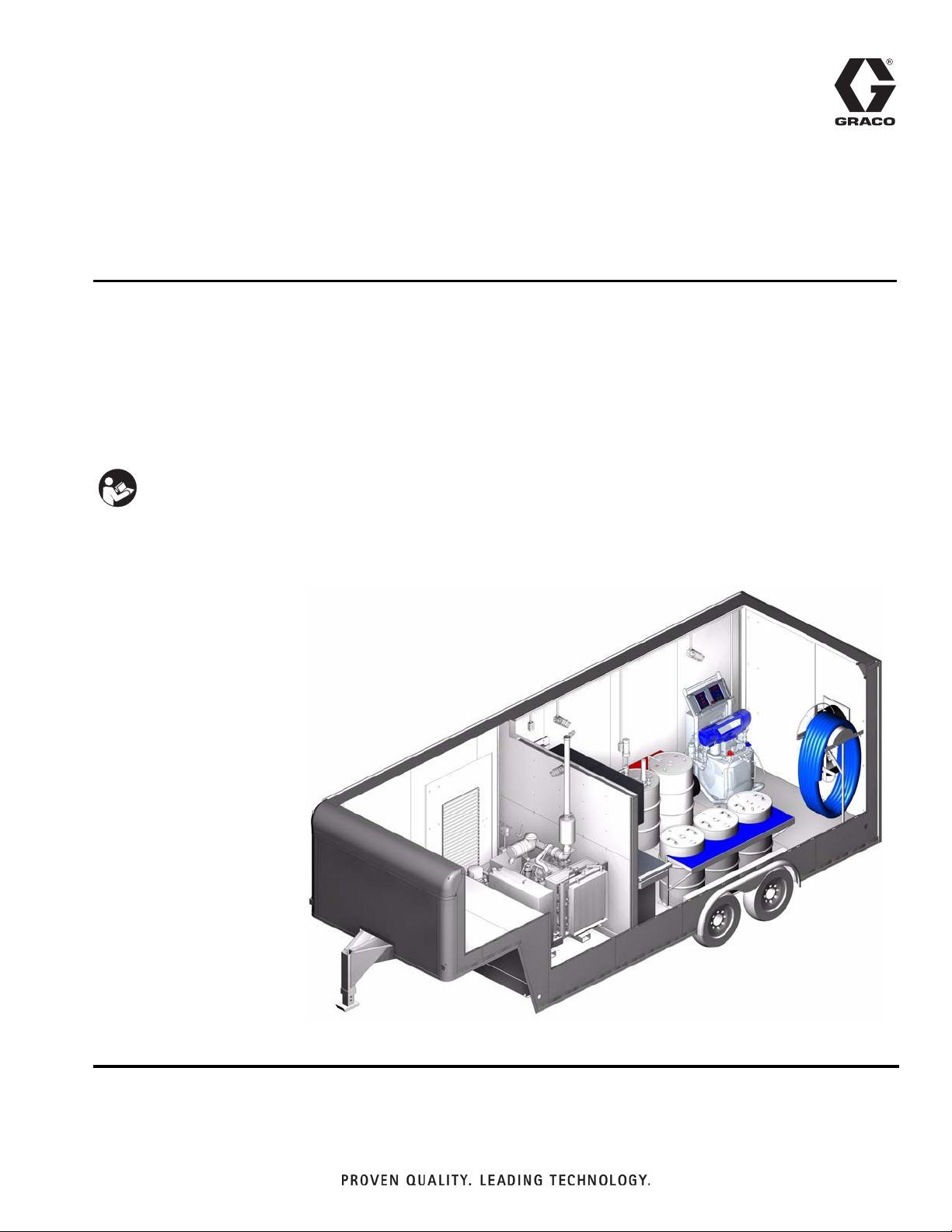
Mobile Spray Rig
For mobile spraying or dispensing of epoxies, polyurethane foam, and polyurea coatings.
Not for use in explosive atmospheres.
120 psi (0.8 MPa, 8.2 bar) Maximum Working Air Pressure
See Technical Data on page 45 and Related Manuals on page 3 for Maximum Working Fluid Pressures
Important Safety Instructions
Read all warnings and instructions in this manual and all
supplied manuals. Save these instructions. See Related
Manuals on page 3.
See page 4 for product configurator information.
312765B
28 ft Trailer Shown
TI12880b
Page 2

Contents
Related Manuals . . . . . . . . . . . . . . . . . . . . . . . . . . . 3
Product Configurator . . . . . . . . . . . . . . . . . . . . . . . 4
Warnings . . . . . . . . . . . . . . . . . . . . . . . . . . . . . . . . 10
Component Identification . . . . . . . . . . . . . . . . . . . 12
Grounding . . . . . . . . . . . . . . . . . . . . . . . . . . . . . . . 18
Transporting Trailer . . . . . . . . . . . . . . . . . . . . . . . . 18
Setup . . . . . . . . . . . . . . . . . . . . . . . . . . . . . . . . . . . . 19
Startup . . . . . . . . . . . . . . . . . . . . . . . . . . . . . . . . . . 24
Pressure Relief Procedure . . . . . . . . . . . . . . . . . . 26
Operation . . . . . . . . . . . . . . . . . . . . . . . . . . . . . . . . 27
Shutdown . . . . . . . . . . . . . . . . . . . . . . . . . . . . . . . . 28
Maintenance . . . . . . . . . . . . . . . . . . . . . . . . . . . . . . 29
Troubleshooting . . . . . . . . . . . . . . . . . . . . . . . . . . . 29
Simplified Electrical Schematics . . . . . . . . . . . . . 30
Simplified Pneumatic Schematic . . . . . . . . . . . . . 38
Simplified Fluid Schematics . . . . . . . . . . . . . . . . . 40
Dimensions . . . . . . . . . . . . . . . . . . . . . . . . . . . . . . 43
Technical Data . . . . . . . . . . . . . . . . . . . . . . . . . . . . 45
Graco Ohio Standard Warranty . . . . . . . . . . . . . . 46
Graco Ohio Information . . . . . . . . . . . . . . . . . . . . 46
2 312765B
Page 3

Related Manuals
Related Manuals
Graco Manuals
These manuals can be found at www.graco.com. See
Product Configurator on page 4 to determine which
components are installed in your assembly. All manuals
for installed components are supplied with each Spray
Rig.
Proportioners
Part Description
311511 Air Reactor Operation Manual
311512 Air Reactor Repair Manual
312062 Hydraulic Reactor Operation Manual
312063 Hydraulic Reactor Repair Manual
312064
312065 Electric Reactor Operation Manual
312066 Electric Reactor Repair Manual
Gun Packages
Part Description
309550 Fusion Air Purge Gun Manual
309856 Fusion Mechanical Purge Gun Manual
311320 D-Gun Manual
311321 GX-7A, GX-7 DI, and GX-7 400 Spray
311322 GAP Pro Spray Gun Manual
311338 Gusmer GX-8 Gun Manual
312666 Fusion ClearShot Gun Manual
313213 Probler P2 Manual
Pumps
Hydraulic Reactor Electrical Diagrams
Manual
Guns Manual
Hoses
Part Description
309572 Power-Lock Heated Hose Manual
Kits
Part Description
309815 Feed Pump Kits Manual
309852 Circulation and Return Tube Kits
Non-Graco Manuals
The following manuals are for non-Graco Spray Rig
components. See Product Configurator on page 4 to
determine which components are installed in your
assembly. All manuals for installed components are supplied with each Spray Rig.
Description
Breathable Air System Manual
Air Dryer Manual
Trailer Manual
Generator Manual
Compressor Manual
Air Conditioning Unit Manual
Band Heaters Manual
NOTE: The manual for each rotary compressor is
included in the generator manual.
Part Description
308479 Husky 1040 Air-Operated Diaphragm
Pumps Manual
311882 T2 2:1 Ratio Transfer Pump Manual
312766 T1 2:1 Ratio Transfer Pump Manual
Agitators
Part Description
308175 Twistork Helix Mixer
312765B 3
Page 4
Product Configurator
Product Configurator
US-G----------------
Code: A B C D E F-G H-I J K L M N O P Q-R S
Configurator Series Level
Tr a i l e r Ty p e
Air Compressor
Proportioner(s)
Air Dryer
Generator
Pump System
Gun
Work Bench
Band Heaters
Air Conditioning
Agitator(s)
Gun Recirculation Kit
Machine Recirculation Kit
An example of the product configurator would be the following configurator code.
US -G-T-M-D-4-N-04-06-1-2-A-1-3-N-2-26-B
Code: A B C D E F-G H-I J K L M N O P Q-R S
Configurator Series Level
Tra i le r Typ e
Air Compressor
Proportioner(s)
Air Dryer
Generator
Pump System
Gun
Work Bench
Band Heaters
Air Conditioning
Agitator(s)
Gun Recirculation Kit
Machine Recirculation Kit
Drum Lids
Drum Lids
Heated Hoses
Breathable Air System
Heated Hoses
Breathable Air System
The following part number fields apply for the Spray Rig part numbering configurator fields.
Code A Part Trailer Type
A U90840 28 ft Trailer, 3-Phase, OEM Insulation,
Dual Proportioner
B U90678 18 ft Modified Truck Box, 3-Phase, Insu-
lated by Graco
C U91000 18 ft Modified Truck Box, 3-Phase, OEM
Insulation
D U91001 18 ft Modified Truck Box, 1-Phase, OEM
Insulation
F U90677 18 ft Modified Truck Box, 1-Phase, Insu-
lated by Graco
G U90380 28 ft Trailer, 3-Phase, OEM Insulation,
Single Proportioner
H U90638 28 ft Trailer, 1-Phase, OEM Insulation, Sin-
gle Proportioner
J U91002 18 ft Modified Truck Box, 3-Phase, OEM
Insulation,
K U91003 18 ft Modified Truck Box, 1-Phase, OEM
Insulation
M U90668 20-28 ft Modified Truck Box, 3-Phase,
OEM Insulation, Single Proportioner
P U90669 20-28 ft Modified Truck Box, 1-Phase,
OEM Insulation, Single Proportioner
Q U91004 20-28 ft Modified Truck Box, 1-Phase,
Insulated by Graco, Single Proportioner
R U91005 20-28 ft Modified Truck Box, 3-Phase,
Insulated by Graco, Single Proportioner
S U90884 20-28 ft Modified Truck Box, 3-Phase,
Insulated by Graco, Dual Proportioner
T U90381 20 ft Trailer, 3-Phase, OEM Insulation
U U90661 20 ft Trailer, 1-Phase, OEM Insulation
V U91006 20-28 ft Modified Truck Box, 1-Phase,
OEM Insulation, Single Proportioner
W U91007 20-28 ft Modified Truck Box, 3-Phase,
OEM Insulation, Single Proportioner
X U90883 20-28 ft Modified Truck Box, 3-Phase,
OEM Insulation, Dual Proportioner
Z U90850 20-28 ft Modified Truck Box, 3-Phase,
OEM Insulation, Dual Proportioner
4 312765B
Page 5

Product Configurator
Code B Part Air Compressor
X U91010 None - Female Quick Connect Fitting Only
A U90757 Rotary (Includes 40 kW, 3-Phase Genera-
tor) No Air Conditioning, 28 ft, 3-Phase
B U90756 Rotary (Includes 40 kW, 3-Phase Genera-
tor), No Air Conditioning, 20 ft, 3-Phase
C U90383 5 hp Horizontal, 3-Phase
D U90384 5 hp Vertical, 3-Phase
E U90385 10 hp Base Mount, 3-Phase
F U90753 Rotary (Includes 40 kW, 1-Phase Genera-
tor) No Air Conditioning, 28 ft, 1-Phase
G U90752 Rotary (Includes 40 kW, 1-Phase Genera-
tor) No Air Conditioning, 20 ft, 1-Phase
H U90672 5 hp Horizontal, 1-Phase
J U90673 5 hp Vertical, 1-Phase
K U90674 10 hp Vertical, 3-Phase, 80 Gallon
M U90754 Rotary (Includes 40 kW, 3-Phase Genera-
tor), With Air Conditioning, 20 ft, 3-Phase
P U90750 Rotary (Includes 40 kW, 1-Phase Genera-
tor), With Air Conditioning, 20 ft, 1-Phase
Q U90755 Rotary (Includes 40 kW, 3-Phase Genera-
tor), With Air Conditioning, 28 ft 3-Phase
R U90751 Rotary (Includes 40 kW, 1-Phase Genera-
tor), With Air Conditioning, 28 ft, 1-Phase
S U90841 Rotary (Includes 40 kW, 3-Phase Genera-
tor), Without Air Conditioning, Dual Proportioner
T U90842 Rotary (Includes 40 kW, 3-Phase Genera-
tor), With Air Conditioning, Dual Proportioner
Code C Part Proportioner(s)
X U91008 None - Wires Only For 100 Amp,
3-Phase
A U90389 H-40, 20.4 kW Heater, 3-phase
B U90390 H-40, 12.0 kW Heater, 1-phase
C U90391 H-40, 15.3 kW Heater, 3-phase
D U90392 H-XP3, 20.4 kW Heater, 3-phase
E U90393 H-25, 8.0 kW Heater, 1-phase
F U90394 H-25, 8.0 kW Heater, 3-phase
G U90395 H-25, 15.3 kW Heater, 1-phase
H U90396 H-25, 15.3 kW Heater, 3-phase
J U90397 H-XP2, 15.3 kW Heater, 1-phase
K U90398 H-XP2, 15.3 kW Heater, 3-phase
L U90399 E-30, 15.3 kW Heater, 1-phase
M U90400 E-30, 15.3 kW Heater, 3-phase
P U90401 E-30, 10.2 kW Heater, 1-phase
Q U90402 E-30, 10.2 kW Heater, 3-phase
R U90403 E-20, 6.0 kW Heater, 1-phase
S U90404 E-20, 6.0 kW Heater, 3-phase
T U90405 E-XP2, 15.3 kW Heater, 1-phase
U U90406 E-XP2, 15.3 kW Heater, 3-phase
V U90844 (Dual) H-25, 8.0 kW Heater, 3-phase
W U90845 (Dual) E-30, 10.2 kW Heater, 3-phase
Y U91074 H-50, 15.3 kW Heater, 3-phase
Z U91075 H-40, 20.4 kW Heater, 3-phase
Code D Part Air Dryer
1 - None - Fittings Only
2 U90366 20 cfm
4 U90365 40 cfm
8 U90843 40 cfm for Dual Proportioners
Code E Part Generator
N-None
A U90760 40 kW, 1-Phase (No Air Conditioning),
20 ft
C U90761 40 kW, 1-Phase (No Air Conditioning),
28 ft
F U90764 40 kW, 3-Phase (No Air Conditioning),
20 ft
H U90765 40 kW, 3-Phase (No Air Conditioning),
28 ft
K U90758 40 kW, 1-Phase (Air Conditioning), 20 ft
M U90759 40 kW, 1-Phase (Air Conditioning), 28 ft
P U90762 40 kW, 3-Phase (Air Conditioning), 20 ft
R U90763 40 kW, 3-Phase (Air Conditioning), 28 ft
312765B 5
Page 6

Product Configurator
Code
F-G
NP - None
01 U90353 Husky 1040 (2 Pumps with Supply
02 U90578 Husky 1040 (2 Pumps with Supply
04 U90414 T2 (2 Pumps with Supply Hoses), 20 ft
05 U90567 T2 (2 Pumps with Supply Hoses), 28 ft
07 U90727 T1 (2 Pumps with Supply Hoses), 20 ft
08 U90728 T1 (2 Pumps with Supply Hoses), 28 ft
11 U90814 System, Supply Lines, 20 ft
12 U90815 System, Supply Lines, 28 ft
13 U90665 Husky 1040 (2 Pumps with Supply
14 U90664 Husky 1040 (2 Pumps with Supply
16 U90739 T2 (2 Pumps with Supply Hoses), 20 ft,
17 U90740 T2 (2 Pumps with Supply Hoses), 28 ft,
19 U90742 T1 (2 Pumps with Supply Hoses), 20 ft,
20 U90743 T1 (2 Pumps with Supply Hoses), 28 ft,
23 U90817 System, Supply Lines, 20 ft, with Electric
24 U90818 System, Supply Lines, 28 ft, with Electric
25 U90885 System, Supply Lines, Dual Proportioners
26 U90886 System, Supply Lines, Dual Proportioners,
27 U90846 T2 (2 Pumps with Supply Hoses), Dual
28 U90847 T2 (2 Pumps with Supply Hoses), Dual
Part Pump System
Hoses), 20 ft
Hoses), 28 ft
Hoses), 20 ft, with Electric Proportioner
Hoses), 28 ft, with Electric Proportioner
with Electric Proportioner
with Electric Proportioner
with Electric Proportioner
with Electric Proportioner
Proportioner
Proportioner
with Electric Proportioner
Proportioners
Proportioners, with Electric Proportioner
Code
H-I
NG - None
01 246101 Fusion Air Purge, Includes AR4242 And
02 246102 Fusion Air Purge, Includes AR4242 And
03 247102 Fusion Flat Air Purge 0438, Qty 1
04 295560 GAP Pro Round 02, Qty 1
05 295552 GAP Pro Flat 02, Qty 1
06 247212 Fusion Mechanical Purge 040, Qty 1
07 295542 GX-7 1/90, Qty 1
08 295541 GX-7 DI 4/213, Qty 1
09 295533 D Gun 70, Qty 1
10 CS20RD Fusion ClearShot, Includes RD2020,
11 CS00RD Fusion ClearShot, Includes RD0000,
12 CS01RD Fusion ClearShot, Includes RD0101,
13 CS02RD Fusion ClearShot, Includes RD0202,
14 CS03RD Fusion ClearShot, Includes RD0303,
15 CS00WD Fusion ClearShot, Includes WD0000,
16 CS20F2 Fusion ClearShot, Includes FL2020 and
17 CS00F2 Fusion ClearShot, Includes FL0000 and
18 CS01F2 Fusion ClearShot, Includes FL0101 and
19 CS02F2 Fusion ClearShot, Includes FL0202 and
20 U90795 Fusion Air Purge, Includes AR4242 and
21 U90796 Fusion Air Purge, Includes AR4242 and
22 U90797 Fusion Flat Air Purge 0438, Qty 2
23 U90798 GAP Pro Round 02, Qty 2
24 U90799 GAP Pro Flat 02, Qty 2
25 U90800 Fusion Mechanical Purge 040, Qty 2
26 U90801 GX-7 1/90, Qty 2
27 U90802 GX-7 DI 4/213, Qty 2
28 U90803 D-Gun 70, Qty 2
29 U90819 Fusion ClearShot, Includes RD2020,
Part Gun
AR5252, Qty 1
AR2020, Qty 1
Qty 1 Gun
Qty 1 Gun
Qty 1 Gun
Qty 1 Gun
Qty 1 Gun
Qty 1 Gun
FT0438, Qty 1 Gun
FT0438, Qty 1 Gun
FT0438, Qty 1 Gun
FT0438, Qty 1 Gun
AR5252, Qty 2
AR2020, Qty 2
Qty 2 Guns
6 312765B
Page 7

Product Configurator
30 U90820 Fusion ClearShot, Includes RD0000,
Qty 2 Guns
31 U90821 Fusion ClearShot, Includes RD0101,
Qty 2 Guns
32 U90822 Fusion ClearShot, Includes RD0202,
Qty 2 Guns
33 U90823 Fusion ClearShot, Includes RD0303,
Qty 2 Guns
34 U90824 Fusion ClearShot, Includes WD0000,
Qty 2 Guns
35 U90825 Fusion ClearShot, Includes FL2020 and
FT0438, Qty 2 Guns
36 U90826 Fusion ClearShot, Includes FL0000 and
FT0438, Qty 2 Guns
37 U90827 Fusion ClearShot, Includes FL0101 and
FT0438, Qty 2 Guns
38 U90828 Fusion ClearShot, Includes FL0202 and
FT0438, Qty 2 Guns
39 U91076 Probler P2 (GCP2R1), Qty 1 Gun
40 U91077 Probler P2 (GCP2R2), Qty 1 Gun
41 U91083 Probler P2 (GCP2R1), Qty 2 Gun
42 U91084 Probler P2 (GCP2R2), Qty 2 Gun
Code J Part Work Benches
N - None
1 U90411 Workbench, Toolbox, Cabinets, Vise,
Small
2 U90412 Workbench, Toolbox, Cabinets, Vise,
Large
4 189233 None - (Gauges)
5 U90848 Toolbox and Upper Cabinets, No Vise or
Lower Cabinets
Code K Part Band Heater(s)
N - None
1 U90045 One Band Heater with Thermostat
2 U90804 Two Band Heaters with Thermostat
Code L Part Air Conditioning
N - None
A U90356 Rooftop Air Conditioning
B U90733 Rooftop Air Conditioning, Low Profile,
Truck Must Be Lower Than 12 ft 6 in.
Overall Height
Code M Part Agitator(s)
N - None
1 U90521 One Twistork Agitator
2 U90805 Two Twistork Agitators
Code N Part Gun Recirculation Kit
N-None
A U90656 Fusion Gun Circulation System
B U90657 GAP Pro Circulation System
C U90793 Fusion Gun Circulation System with
Machine Recirculation
F U90794 GAP Pro Circulation System with Machine
Recirculation
G U90829 ClearShot Gun Circulation System
H U90830 ClearShot Gun Circulation System with
Machine Recirculation
J U90851 Fusion Gun Circulation System, Dual Pro-
portioners
K U90852 GAP Pro Circulation System, Dual Propor-
tioners
M U90854 Fusion Gun Circulation System with
Machine Recirculation, Dual Proportioners
P U90855 GAP Pro Circulation System with Machine
Recirculation, Dual Proportioners
Q U90853 ClearShot Gun Circulation System, Dual
Proportioners
R U90856 ClearShot Gun Circulation System with
Machine Recirculation, Dual Proportioners
S U91078 P2 Gun Circulation System, Single Pro-
portioner
T U91081 P2 Gun Circulation System with Machine
Recirculation, Single Proportioner
U U91080 P2 Gun Circulation System, Dual Propor-
tioner
V U91082 P2 Gun Circulation System with Machine
Recirculation, Dual Proportioner
Code O Part Machine Recirculation Kit
N-None
A U90561 Machine Recirculation, 28 ft Trailer or
20-28 ft Truck
B U90355 Machine Recirculation, 20 ft Trailer or 18 ft
Tr uc k
D U90849 Machine Recirculation, 28 ft Trailer or
20-28 ft Truck, Dual Proportioner
Code P Part Drum Lids
N-None
1 U90053 One Blue Drum Lid
2 U90052 One Red Drum Lid
3 U90413 One Red and One Blue Drum Lid
312765B 7
Page 8

Product Configurator
Code
Q-R
NH - None
01 U90715 160 ft, 2000 psi, (3) 3/8 with Fluid Temper-
02 U90453 210 ft, 2000 psi, (4) 3/8 with Fluid Temper-
03 U90454 310 ft, 2000 psi, (6) 3/8 with Fluid Temper-
04 U90670 310 ft, 2000 psi, (5) 3/8 with Fluid Temper-
05 U90455 410 ft, 2000 psi, (8) 3/8 with Fluid Temper-
06 U90680 410 ft, 2000 psi, (7) 3/8 with Fluid Temper-
07 U90716 160 ft, 2000 psi, (3) 3/8 with Fluid Temper-
08 U90456 210 ft, 2000 psi, (4) 3/8 with Fluid Temper-
09 U90681 310 ft, 2000 psi, (6) 3/8 with Fluid Temper-
10 U90457 310 ft, 2000 psi, (5) 3/8 with Fluid Temper-
11 U90682 410 ft, 2000 psi, (8) 3/8 with Fluid Temper-
12 U90458 410 ft, 2000 psi, (7) 3/8 with Fluid Temper-
13 U90717 160 ft, 2000 psi, (3) 3/8 with Fluid Temper-
14 U90465 210 ft, 2000 psi, (4) 3/8 with Fluid Temper-
15 U90466 310 ft, 2000 psi, (6) 3/8 with Fluid Temper-
16 U90683 310 ft, 2000 psi, (5) 3/8 with Fluid Temper-
17 U90467 410 ft, 2000 psi, (8) 3/8 with Fluid Temper-
Part Heated Hoses
ature Sensor, No Scuff-Guard,
Non-assembled
ature Sensor, No Scuff-Guard,
Non-assembled
ature Sensor, No Scuff-Guard,
Non-assembled
ature Sensor, (1) 3/8 No Fluid Temperature Sensor, No Scuff-Guard,
Non-assembled
ature Sensor, No Scuff-Guard,
Non-assembled
ature Sensor, (1) 3/8 No Fluid Temperature Sensor, No Scuff-Guard,
Non-assembled
ature Sensor, Scuff-Guard, Non-assembled
ature Sensor, Scuff-Guard, Non-assembled
ature Sensor, Scuff-Guard, Non-assembled
ature Sensor, (1) 3/8 No Fluid Temperature Sensor, Scuff-Guard, Non-assembled
ature Sensor, Scuff-Guard, Non-assembled
ature Sensor, (1) 3/8 No Fluid Temperature Sensor, Scuff-Guard, Non-assembled
ature Sensor, No Scuff-Guard, Assembled
ature Sensor, No Scuff-Guard, Assembled
ature Sensor, No Scuff-Guard, Assembled
ature Sensor, (1) 3/8 No Fluid Temperature Sensor, No Scuff-Guard, Assembled
ature Sensor, No Scuff-Guard, Assembled
18 U90684 410 ft, 2000 psi, (7) 3/8 with Fluid Temper-
ature Sensor, (1) 3/8 No Fluid Temperature Sensor, No Scuff-Guard, Assembled
19 U90718 160 ft, 2000 psi, (3) 3/8 with Fluid Temper-
ature Sensor, Scuff-Guard, Assembled
20 U90468 210 ft, 2000 psi, (4) 3/8 with Fluid Temper-
ature Sensor, Scuff-Guard, Assembled
21 U90685 310 ft, 2000 psi, (6) 3/8 with Fluid Temper-
ature Sensor, Scuff-Guard, Assembled
22 U90469 310 ft, 2000 psi, (5) 3/8 with Fluid Temper-
ature Sensor, (1) 3/8 No Fluid Temperature Sensor, Scuff-Guard, Assembled
23 U90686 410 ft, 2000 psi, (8) 3/8 with Fluid Temper-
ature Sensor, Scuff-Guard, Assembled
24 U90470 410 ft, 2000 psi, (7) 3/8 with Fluid Temper-
ature Sensor, (1) 3/8 No Fluid Temperature Sensor, Scuff-Guard, Assembled
25 U90719 160 ft, 3500 psi, (3) 3/8 with Fluid Temper-
ature Sensor, No Scuff-Guard, Assembled
26 U90471 210 ft, 3500 psi, (4) 3/8 with Fluid Temper-
ature Sensor, No Scuff-Guard, Assembled
27 U90472 310 ft, 3500 psi, (4) 1/2 with Fluid Temper-
ature Sensor, (2) 3/8 with Fluid Temperature Sensor, No Scuff-Guard, Assembled
28 U90473 410 ft, 3500 psi, (6) 1/2 with Fluid Temper-
ature Sensor, (2) 3/8 with Fluid Temperature Sensor, No Scuff-Guard, Assembled
29 U90720 160 ft, 3500 psi, (3) 3/8 with Fluid Temper-
ature Sensor, Scuff-Guard, Assembled
30 U90474 210 ft, 3500 psi, (4) 3/8 with Fluid Temper-
ature Sensor, Scuff-Guard, Assembled
31 U90475 310 ft, 3500 psi, (4) 1/2 with Fluid Temper-
ature Sensor, (2) 3/8 with Fluid Temperature Sensor, Scuff-Guard, Assembled
32 U90476 410 ft, 3500 psi, (6) 1/2 with Fluid Temper-
ature Sensor, (2) 3/8 with Fluid Temperature Sensor, Scuff-Guard, Assembled
33 U90721 160 ft, 3500 psi, (4) 3/8 with Fluid Temper-
ature Sensor, No Scuff-Guard,
Non-assembled
34 U90459 210 ft, 3500 psi, (4) 3/8 with Fluid Temper-
ature Sensor, Scuff-Guard, Non-assembled
35 U90460 310 ft, 3500 psi, (4) 1/2 with Fluid Temper-
ature Sensor, (2) 3/8 with Fluid Temperature Sensor, No Scuff-Guard,
Non-assembled
36 U90461 410 ft, 3500 psi, (6) 1/2 with Fluid Temper-
ature Sensor, (2) 3/8 with Fluid Temperature Sensor, No Scuff-Guard,
Non-assembled
8 312765B
Page 9

Product Configurator
37 U90722 160 ft, 3500 psi, (4) 3/8 with Fluid Temper-
ature Sensor, Scuff-Guard, Non-assembled
38 U90462 210 ft, 3500 psi, (4) 3/8 with Fluid Temper-
ature Sensor, Scuff-Guard, Non-assembled
39 U90463 310 ft, 3500 psi, (4) 1/2 with Fluid Temper-
ature Sensor, (2) 3/8 with Fluid Temperature Sensor, Scuff-Guard, Non-assembled
40 U90464 410 ft, 3500 psi, (6) 1/2 with Fluid Temper-
ature Sensor, (2) 3/8 with Fluid Temperature Sensor, Scuff-Guard, Non-assembled
41 U90857 (2) 160 ft, 2000 psi, (3) 3/8 with Fluid Tem-
perature Sensor, No Scuff-Guard,
Non-assembled
42 U90861 (2) 160 ft, 2000 psi, (3) 3/8 with Fluid Tem-
perature Sensor, Scuff-Guard,
Non-assembled
43 U90865 (2) 160 ft, 2000 psi, (3) 3/8 with Fluid Tem-
perature Sensor, No Scuff-Guard, Assembled
44 U90869 (2) 160 ft, 2000 psi, (3) 3/8 with Fluid Tem-
perature Sensor, Scuff-Guard, Assembled
45 U90858 (2) 210 ft, 2000 psi, (4) 3/8 with Fluid Tem-
perature Sensor, No Scuff-Guard,
Non-assembled
46 U90862 (2) 210 ft, 2000 psi, (4) 3/8 with Fluid Tem-
perature Sensor, Scuff-Guard,
Non-assembled
47 U90866 (2) 210 ft, 2000 psi, (4) 3/8 with Fluid Tem-
perature Sensor, No Scuff-Guard, Assembled
48 U90870 (2) 210 ft, 2000 psi, (4) 3/8 with Fluid Tem-
perature Sensor, Scuff-Guard, Assembled
49 U90859 (2) 310 ft, 2000 psi, (6) 3/8 with Fluid Tem-
perature Sensor, No Scuff-Guard,
Non-assembled
50 U90860 (2) 310 ft, 2000 psi, (5) 3/8 with Fluid Tem-
perature Sensor, (1) 3/8 No Fluid Temperature Sensor, No Scuff-Guard,
Non-assembled
51 U90863 (2) 310 ft, 2000 psi, (6) 3/8 with Fluid Tem-
perature Sensor, Scuff-Guard,
Non-assembled
52 U90864 (2) 310 ft, 2000 psi, (5) 3/8 with Fluid Tem-
perature Sensor, (1) 3/8 No Fluid Temperature Sensor, Scuff-Guard,
Non-assembled
53 U90867 (2) 310 ft, 2000 psi, (6) 3/8 with Fluid Tem-
perature Sensor, No Scuff-Guard, Assembled
54 U90868 (2) 310 ft, 2000 psi, (5) 3/8 with Fluid Tem-
perature Sensor, (1) 3/8 No Fluid Temperature Sensor, No Scuff-Guard, Assembled
55 U90871 (2) 310 ft, 2000 psi, (6) 3/8 with Fluid Tem-
perature Sensor, Scuff-Guard, Assembled
56 U90872 (2) 310 ft, 2000 psi, (5) 3/8 with Fluid Tem-
perature Sensor, (1) 3/8 No Fluid Temperature Sensor, Scuff-Guard, Assembled
Code S Part Breathable Air System
N-None
B U91014 One 300 ft Breathing System, Includes
One Mask, Lens, One 300 ft Hose, Hose
Hanger, Service Kit
D U91015 Two 300 ft Breathing Systems, Includes
(2) Masks, (50) Lens, (2) 300 ft Hoses, (2)
Hose Hangers, (1) Service Kit
312765B 9
Page 10
Warnings
Warnings
For complete warnings for installed components,
see supplied manuals. See Related Manuals on
page 3.
The following warnings are for the setup, use, grounding, maintenance, and repair of this equipment. The exclamation point symbol alerts you to a general warning and the hazard symbol refers to procedure-specific risk. Refer back
to these warnings. Additional, product-specific warnings may be found throughout the body of this manual where
applicable.
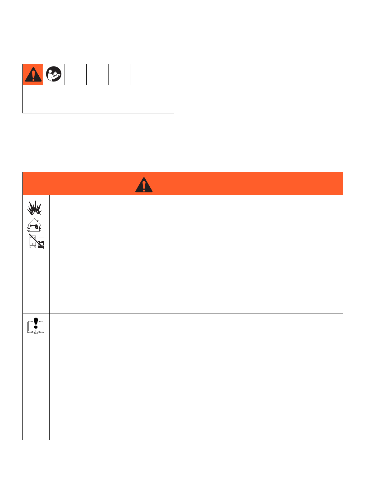
WARNING
WARNINGWARNINGWARNING
FIRE AND EXPLOSION HAZARD
Flammable fumes, such as solvent and paint fumes, in work area can ignite or explode. To help prevent
fire and explosion:
• Use equipment only in well ventilated area.
• Eliminate all ignition sources; such as pilot lights, cigarettes, portable electric lamps, and plastic drop
cloths (potential static arc).
• Keep work area free of debris, including solvent, rags and gasoline.
• Do not plug or unplug power cords, or turn power or light switches on or off when flammable fumes
are present.
• Ground all equipment in the work area. See Grounding instructions.
• Use only grounded hoses.
• Hold gun firmly to side of grounded pail when triggering into pail.
• If there is static sparking or you feel a shock, stop operation immediately. Do not use equipment
until you identify and correct the problem.
• Keep a working fire extinguisher in the work area.
EQUIPMENT MISUSE HAZARD
Misuse can cause death or serious injury.
• Do not operate the unit when fatigued or under the influence of drugs or alcohol.
• Do not exceed the maximum working pressure or temperature rating of the lowest rated system
component. See Technical Data in all equipment manuals.
• Use fluids and solvents that are compatible with equipment wetted parts. See Technical Data in all
equipment manuals. Read fluid and solvent manufacturer’s warnings. For complete information
about your material, request MSDS forms from distributor or retailer.
• Check equipment daily. Repair or replace worn or damaged parts immediately with genuine manufacturer’s replacement parts only.
• Do not alter or modify equipment.
• Use equipment only for its intended purpose. Call your distributor for information.
• Route hoses and cables away from traffic areas, sharp edges, moving parts, and hot surfaces.
• Do not kink or over bend hoses or use hoses to pull equipment.
• Keep children and animals away from work area.
• Comply with all applicable safety regulations.
10 312765B
Page 11
Warnings
WARNING
WARNINGWARNINGWARNING
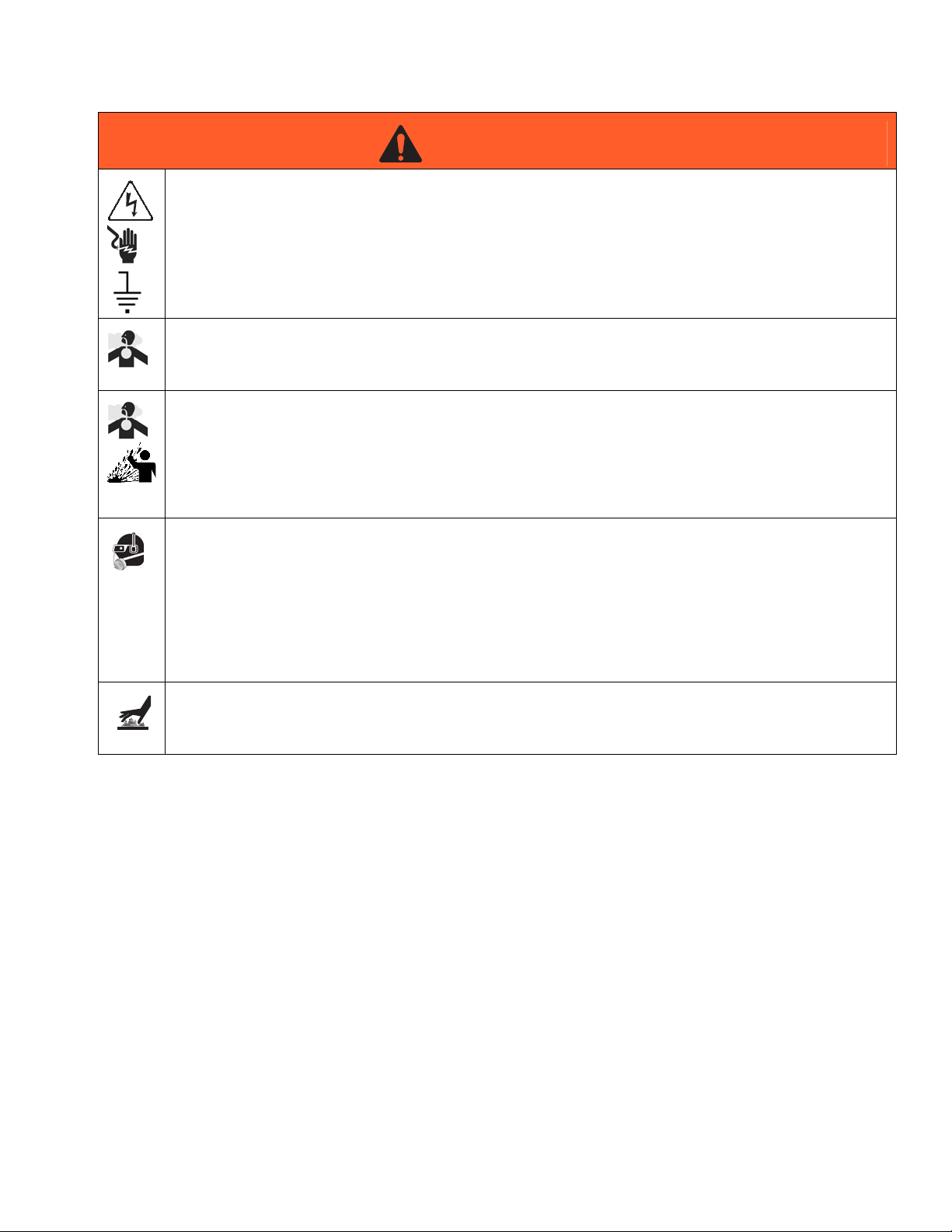
ELECTRIC SHOCK HAZARD
Improper grounding, setup, or usage of the system can cause electric shock.
• Turn off and disconnect power at main switch before disconnecting any cables and before servicing
equipment.
• Connect only to grounded power source.
• All electrical wiring must be done by a qualified electrician and comply with all local codes and
regulations.
CARBON MONOXIDE HAZARD
Exhaust contains poisonous carbon monoxide, which is colorless and odorless. Breathing carbon
monoxide can cause death. Do not operate in an enclosed area.
TOXIC FLUID OR FUMES HAZARD
Toxic fluids or fumes can cause serious injury or death if splashed in the eyes or on skin, inhaled, or
swallowed.
• Read MSDS’s to know the specific hazards of the fluids you are using.
• Store hazardous fluid in approved containers, and dispose of it according to applicable guidelines.
• Always wear impervious gloves when spraying or cleaning equipment.
PERSONAL PROTECTIVE EQUIPMENT
You must wear appropriate protective equipment when operating, servicing, or when in the operating
area of the equipment to help protect you from serious injury, including eye injury, inhalation of toxic
fumes, burns, and hearing loss. This equipment includes but is not limited to:
• Protective eyewear
• Clothing and respirator as recommended by the fluid and solvent manufacturer
•Gloves
• Hearing protection
BURN HAZARD
Equipment surfaces and fluid that’s heated can become very hot during operation. To avoid severe
burns, do not touch hot fluid or equipment. Wait until equipment/fluid has cooled completely.
312765B 11
Page 12
Component Identification
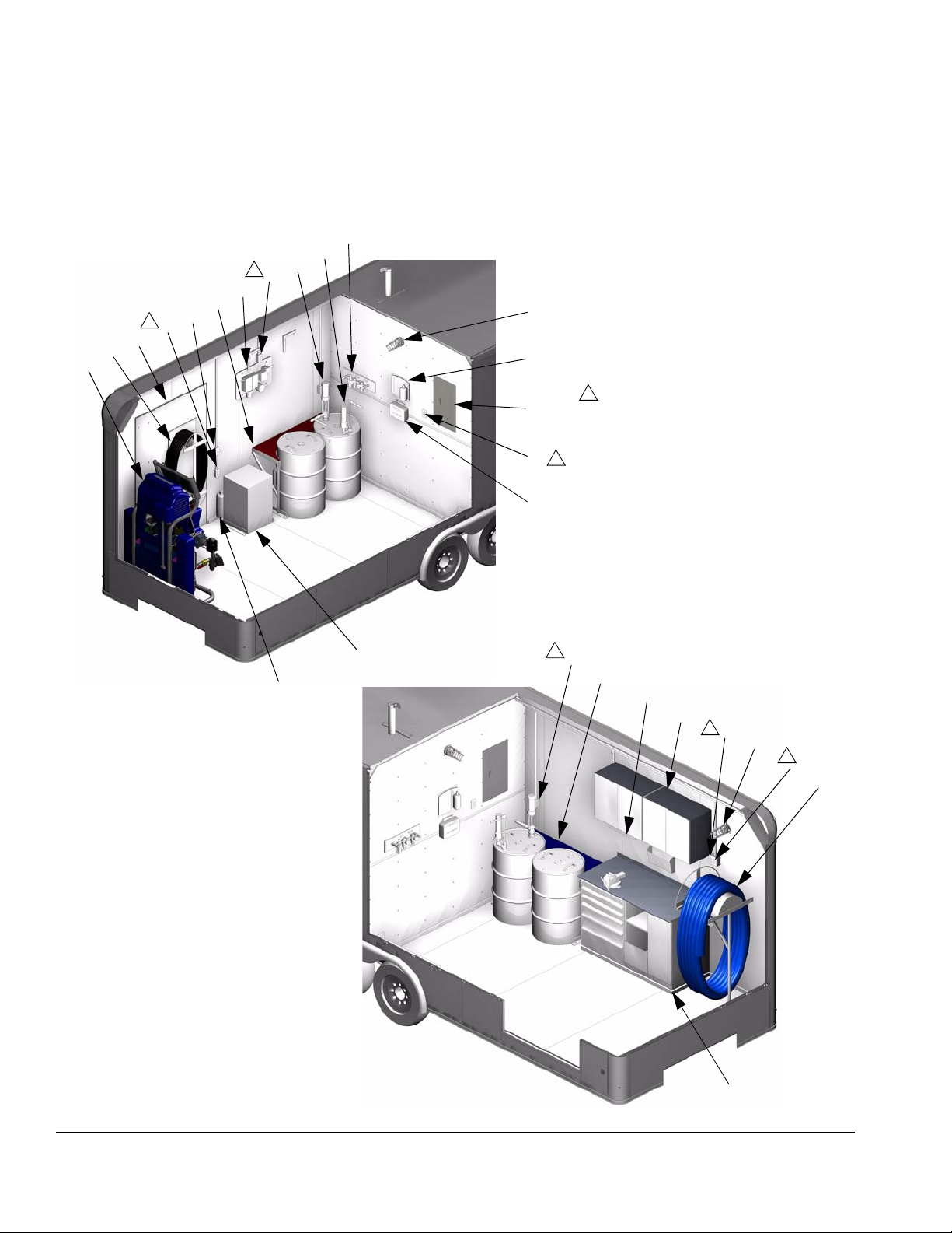
Component Identification
20 ft Trailer
F
K
L
1
V
E
C
S
1
V
T
D
A
J
G
R
W
H
H
1
See Power Sources on page 19 for a closer
view of which outlets Shore Power supplies.
Generator Power supplies all outlets.
1
Key:
N
A Proportioner
BAir Dryer
C Chemical Drums and Rack
D Breathable Air Hose and Rack
E Breathing Air Filter System
F Air Regulators Assembly
G Emergency Eye Wash Station
H First Aid Kit
J 120V Lights
K Agitator
L Pump (Stick Pump shown)
M Work Bench and Cabinets
N Fire Extinguisher
P Heated Hoses and Rack
R Electrical Panel
SLight Switch
TDoor
U Fluorescent Light
V Outlet powered only by Generator
Power
W Outlet powered by both Generator
Power and Shore Power
TI12886a
1
B
V
C
U
M
W
1
J
1
V
P
TI12887a
M
FIG. 1: Main Room
12 312765B
Page 13
20 ft Trailer, continued
J
AE
W
1
S
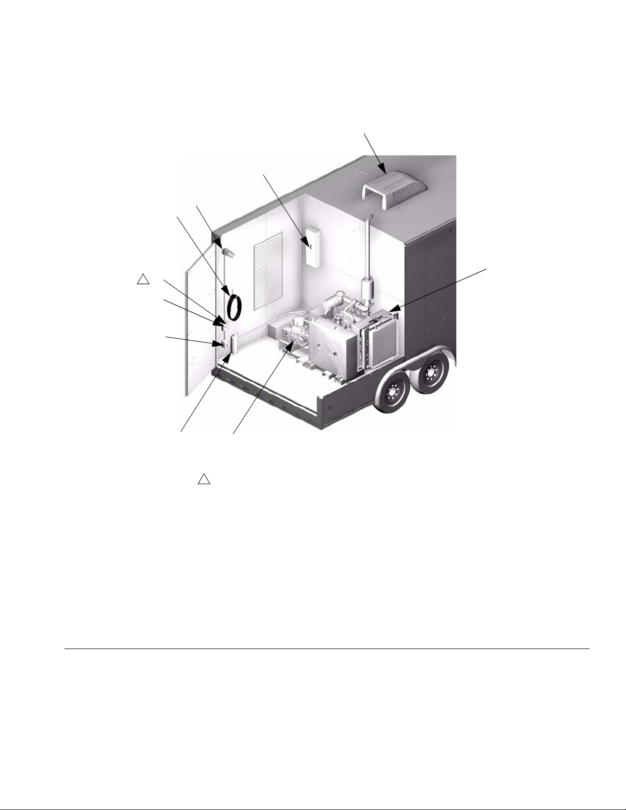
Component Identification
AB
AD
AA
AF
TI12888b
N
AC
1
See Power Sources on page 19 for a closer view of which outlets
Shore Power supplies. Generator Power supplies all outlets.
Key:
AA Generator
AB Air Conditioner
AC Air Compressor
AD Main Breaker
AE Shore Power Extension Cord
AF Shore/Generator Power Switch
FIG. 2: Generator Room
312765B 13
Page 14
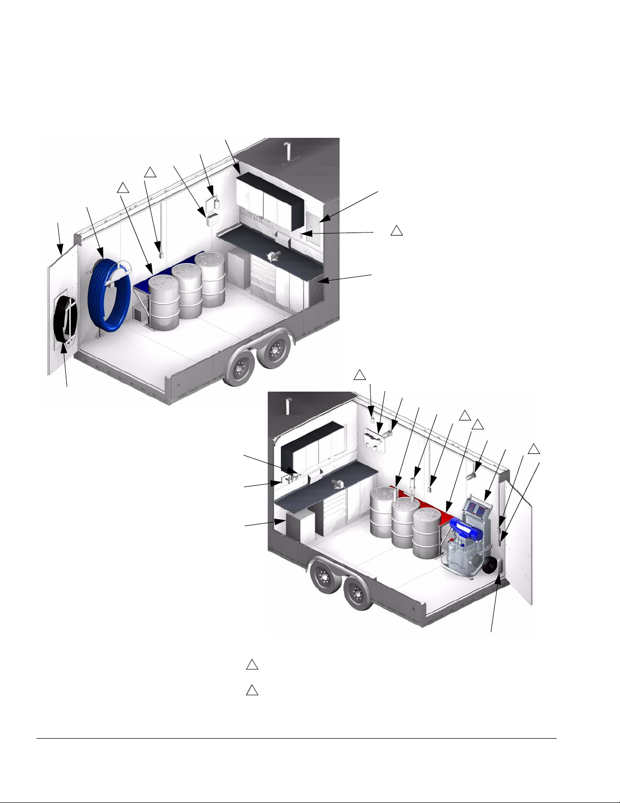
Component Identification
Single Proportioner 28 ft Trailer and Truck Box
M
G
H
V
2
C
1
P
T
R
W
2
M
D
28 ft Trailer Shown
Key:
A Proportioner
BAir Dryer
C Chemical Drums and Rack
D Breathable Air Hose and Rack
E Breathing Air Filter System
F Air Regulators Assembly
G Emergency Eye Wash Station
H First Aid Kit
J 120V Lights
K Agitator
L Pump (Stick Pump shown)
M Work Bench and Cabinets
N Fire Extinguisher
P Heated Hoses and Rack
R Electrical Panel
S Light Switch
TDoor
U Fluorescent Light
V Outlet powered only by Generator
Power
W Outlet powered by both Generator
Power and Shore Power
TI12883a
V
2
E
J
K
L
2
V
C
1
U
F
B
28 ft Trailer Shown
1
The 18 ft truck box has a two-drum chemical rack instead of a three-drum
chemical rack. All other truck boxes have a three drum chemical rack.
2
See Power Sources on page 19 for a closer view of which outlets Shore Power
supplies. Generator Power supplies all outlets.
J
A
V
2
S
TI12884a
N
FIG. 3: Main Room
14 312765B
Page 15

Single Proportioner 28 ft Trailer
and Truck Box continued
AB
J
AD
AE
W
2
S
Component Identification
AA
1
AF
28 ft Trailer Shown
FIG. 4: Generator Room
N
1
Only the 28 ft trailer has the gooseneck area.
2
See Power Sources on page 19 for a closer view of which outlets
Shore Power supplies. Generator Power supplies all outlets.
AC
Key:
AA Generator
AB Air Conditioner
AC Air Compressor
AD Main Breaker
AE Shore Power Extension Cord
AF Shore/Generator Power Switch
TI12885b
312765B 15
Page 16

Component Identification
Dual Proportioner 28 ft Trailer and 20-28 ft Truck Box
A
G
H
V
1
D
C
P
T
TI12889a
R
W
1
A
1
See Power Sources on page 19 for a closer
view of which outlets Shore Power supplies.
Generator Power supplies all outlets.
20 ft Truck Box Shown
Key:
A Proportioner
BAir Dryer
C Chemical Drums and Rack
D Breathable Air Hose and Rack
E Breathing Air Filter System
F Air Regulators Assembly
G Emergency Eye Wash Station
H First Aid Kit
J 120V Lights
K Agitator
L Pump (Stick Pump shown)
M Tool Box and Cabinets
N Fire Extinguisher
P Heated Hoses and Rack
R Electrical Panel
S Light Switch
T Door
U Fluorescent Light
V Outlet powered only by Generator
Power
W Outlet powered by both Generator
Power and Shore Power
M
U
F
20 ft Truck Box Shown
1
V
E
J
K
L
1
V
D
J
C
P
T
V
1
S
TI12890a
N
FIG. 5: Main Room
16 312765B
Page 17

Dual Proportioner 28 ft Trailer
and 20-28 ft Truck Box,
continued
20 ft Truck Box Shown
AB
B
AD
AE
W
1
S
Component Identification
AJ
AA
FIG. 6: Generator Room
AF
N
TI12891b
AC
1
See Power Sources on page 19 for a closer view of which outlets
Shore Power supplies. Generator Power supplies all outlets.
Key:
AA Generator
AB Air Conditioner
AC Air Compressor
AD Main Breaker
AE Shore Power Extension Cord
AF Shore/Generator Power Switch
AG Air Tank
312765B 17
Page 18

Grounding
Grounding
See grounding procedure and related warnings in
supplied manuals. See Related Manuals on page 3.
The trailer must be grounded. In the event of an electrical short circuit, grounding reduces the risk of electric
shock by providing an escape wire for the electric current.
When grounding the trailer, ground to one of the bolt
holes on the rear, side of generator block. See F
Have a qualified electrician connect the grounding wire
to the generator. Check with national electric code for
grounding of mobile electric units. Be sure your installation complies with all National, State, and Local safety
and fire codes.
IG. 7.
Transporting Trailer
• Do not run generator while trailer is in motion.
• Do not exceed the gross vehicle weight requirement. See Technical Data on page 45.
• See warnings in trailer manual. See Related Man-
uals on page 3.
1. Read trailer manual before transporting or loading
the trailer. See Related Manuals on page 3.
2. Follow Pressure Relief Procedure, page 26.
3. Follow Short-Term Shutdown procedure, page 28.
4. Ensure that drums are properly secured into drum
holders. Tighten drum straps to ensure that they
don’t move during transport.
5. Lock tool cabinet and secure all loose articles in
trailer.
F
IG. 7: Generator Grounding Point
6. Ensure all hoses are completely in trailer/truck box
and on support racks.
7. Shut and lock all trailer doors.
TI12895a
18 312765B
Page 19

Setup
Setup
See setup procedure and related warnings in supplied manuals. See Related Manuals on page 3.
Power Sources
The trailer has two options for power sources. Generator
Power uses the electricity provided by the generator to
provide power to all of the components and outlets in the
trailer except for the 12V lights. Shore Power uses electricity from an external source, supplied through the
Shore Power extension cord, to provide power to certain
outlets in the trailer.
NOTE: Shore Power outlets are labeled with a plaque.
Outlets Powered by Shore Power in 20 ft Trailers
• The left two outlets of the 4-gang outlet in the main
room, on the driver side wall of the trailer
• The two-plug outlet in the main room to the left of
the electrical panel, on the partition wall
• The outlet (W) in the generator room
TI12887a
FIG. 8: Outlets Powered by Shore Power in
20 ft Trailers
TI12888b
312765B 19
Page 20

Setup
Outlets Powered by Shore Power in 28 ft Trailer and
Modified Truck Boxes
• The two-plug outlet in the main room to the left of
the electrical panel, on the partition wall
• The outlet (W) in the generator room
Single Proportioner,
20 ft Trailer Shown
TI12883a
F
IG. 9: Outlets Powered by Shore Power in
28 ft Trailers
TI12885b
20 312765B
Page 21

Setup
Shore Power
Shore Power can be used to provide power to certain
outlets in the trailer. The powered outlets can be used to
run low amperage items.
1. Turn main breaker off.
2. Turn generator off.
3. Turn Shore/Generator Power Switch (AF) to the
“OFF” position. See F
Shore Power
IG. 10
F
IG. 10.
Generator Power
TI13945a
Generator Power
When using Generator Power, all outlets in the trailer
are hot, including Shore Power outlets.
1. Turn off main breaker.
2. Turn Shore/Generator Power Switch (AF) to the
“OFF” position. See F
Shore Power
IG. 12
F
3. Start generator. See Startup instructions on
page 24.
IG. 12.
Generator Power
TI13945a
4. Route Shore Power extension cord (AE) out of the
trailer through the outlet in the floor below the Shore
Power rack.
5. Plug Shore Power extension cord (AE) into a
grounded 110 V outlet.
6. Turn Shore/Generator Power Switch (AF) to the
“SHORE” position. See F
IG. 11.
Shore Power
Generator Power
TI13943a
FIG. 11: Shore Power Setup
4. Turn Shore/Generator Power Switch (AF) to the
“GEN” position. See F
IG. 13.
Shore Power
Generator Power
TI13394a
IG. 13: Generator Power Setup
F
5. Turn on main breaker in the generator room.
7. Turn on main breaker.
312765B 21
Page 22

Setup
Air Regulators Assembly
The left air pressure regulator on the air regulators
assembly (F) supplies air to the transfer pump and
should be set according to air inlet recommendations in
the transfer pump manual. Pump fluid outlet pressure
may vary based on air inlet pressure. Verify the fluid outlet pressure meets proportioner fluid inlet recommendations in Proportioner manual. See Related Manuals on
page 3.
The right air pressure regulator supplies air to gun via
the proportioner and should be set according to air inlet
recommendations in the gun manual. See Related
Manuals on page 3. Verify both regulators are set correctly. Fill ISO pump lube reservoir as required.
Hose Connections
See Simplified Pneumatic Schematic on page 38,
and Simplified Fluid Schematics on page 40.
For more information, see Heated Hose manual and Circulation and Return Tube Kits manual listed in Related
Manuals section on page 3.
Feed System
See setup instructions and related warnings in supplied manuals. See Related Manuals on page 3.
NOTICE
To prevent cross-contamination of the equipment’s
wetted parts, never interchange component A (isocyanate) and component B (resin) parts. Always use
the red drum rack for ISO and the blue drum rack for
resin.
1. Install drums into rack (C). Tighten drum straps.
2. Install drum lids if included.
3. Install agitator, stick pumps, and/or riser tubes if
included.
4. Attach feed system hoses.
Proportioner and Gun
See Proportioner and Gun manuals for related setup
instructions. See Related Manuals on page 3.
22 312765B
Page 23

Air Conditioning
1. Verify Air Conditioning breaker is in the “ON” position.
2. See setup instructions in Air Conditioning manual.
See Related Manuals on page 3.
Breathable Air System
See setup instructions and related warnings in supplied manuals. See Related Manuals on page 3.
1. Verify breathing air filter system is plugged in.
2. Set setup instructions in Breathable Air System
manual. See Related Manuals on page 3.
Setup
Band Heaters
See setup instructions and related warnings in supplied manuals. See Related Manuals on page 3.
NOTICE
Band heaters may char material if temperature setting is too high.
1. Wrap the band heaters around the drums and connect velcro straps to hold the heaters in place.
2. Verify the band heater power cable is plugged in.
3. See setup instructions in Band Heaters manual.
See Related Manuals on page 3.
312765B 23
Page 24

Startup
Startup
See startup instructions and related warnings in
supplied manuals. See Related Manuals on page 3.
Prepare for Generator Startup
1. Ensure main breaker for the generator is in the OFF
position. The main breaker is the only breaker
located in the generator room.
2. Turn Shore/Generator Power Switch (AF) to the
“GEN” position.
3. With trailer level, check fuel, oil, and coolant fluid
levels on generator.
NOTICE
To prevent damage to spray machine and generator,
do not run generator out of fuel. Follow shut down
procedure on page 28 when fuel level is getting low.
Start Generator
NOTE: Refer to generator operator’s manual for cold
weather startup instructions.
8. Press and hold bypass button.
4. Check oil in compressor.
5. Check oil level in lube cup on air regulators assembly.
6. Close water bleed valve on compressor.
7. Ensure proportioner is turned off.
TI12894a1
FIG. 14: Generator Bypass Button
9. Turn ignition switch to start position until engine
starts.
10. Release ignition switch and bypass button.
11. Wait at least five minutes after starting generator for
readout on digital voltage/amp meter in main room
to stabilize.
24 312765B
Page 25

Start Trailer Components
12. Turn on main breaker in the generator room.
13. Verify voltage and frequency displayed on the digital
voltage/amp meter. With engine at normal operating
temperature and not under load, voltage should be
220V +/- 1% and frequency should be
60Hz +5%/-2%.
14. Start proportioner. See Proportioner manual for
instructions, see Related Manuals on page 3.
15. Start compressor.
For all non-screw compressors, engage starter.
Verify readout on air pressure gauge on compressor.
For screw compressors, open ball valve on compressor. See F
IG. 15.
Startup
TI12894a
F
IG. 15: Screw Compressor Ball Valve
16. Verify air dryer is on. See Related Manuals on
page 3.
17. Turn on agitators and pumps. See Related Manu-
als on page 3.
Foam Resins with 245fa Blowing Agents
New foam blowing agents will froth at temperatures
above 90°F (33°C) when not under pressure, especially if agitated. Maintain proper temperature inside
trailer.
18. If required, see Related Manuals on page 3 for
other non-Graco component startup instructions.
312765B 25
Page 26

Pressure Relief Procedure
Pressure Relief Procedure
Chemical Pressure Relief
1. Turn off feed pumps and agitators if used.
See pressure relief procedure and related warnings
in supplied manuals. See Related Manuals on
page 3.
Generator pressure must be relieved prior to performing
generator maintenance or repair. See generator manual.
Air Pressure Relief
1. For rotary compressors, open ball valve on compressor. See F
For all other compressors, open service valve on
compressor.
IG. 16.
2. Turn off proportioner.
3. Relieve pressure in gun and perform gun shutdown
procedure. See Gun manual. See Related Manuals
on page 3.
4. Relieve pressure in proportioner. See Proportioner
manual. See Related Manuals on page 3.
Hydraulic Pressure Relief
Only the Hydraulic Reactor has hydraulic pressure. See
the Hydraulic Reactor manual for hydraulic pressure
relief procedure.
TI12894a
F
IG. 16: Rotary Compressor Ball Valve
2. For dual proportioner Spray Rigs, open water
bleed valve located on the bottom of the air
tank (AG).
26 312765B
Page 27

Operation
See operation instructions and related warnings in
supplied manuals. See Related Manuals on page 3.
Trailer Interior Lights
120V Lights
The trailer interior lights on the walls and the fluorescent
light under the cabinet (if installed) can be powered by
either Generator or Shore Power. To use these lights,
setup Generator Power or Shore Power, see Setup on
page 19. There is one light switch for the 120V lights in
each room.
Operation
12V Lights
NOTE: Modified truck boxes will only include 12V lights
if the customer-provided truck box comes with 12V
lights.
The trailer interior lights on the ceiling are powered by
the truck through the 7-way connector. To use the 12V
lights, connect the trailer 7-way connector to the truck.
There is one main light switch for the 12V lights in each
room. There is also a switch on each light.
312765B 27
Page 28

Shutdown
Shutdown
8. Run generator unloaded for at least two minutes to
allow engine to cool. See generator operator’s manual for details.
See shutdown instructions and related warnings in
supplied manuals. See Related Manuals on page 3.
Short-Term Shutdown
1. Turn off proportioner. Refer to proportioner manual
for shutdown procedure. See Related Manuals on
page 3.
2. Relieve chemical pressure. See Pressure Relief
Procedure on page 26.
3. Properly seal supply drums.
4. Ensure desiccant dryer is in proper working condition.
5. Turn off air compressor.
• For screw compressors, close the ball valve.
See F
IG. 17, ball valve is shown open.
9. Turn generator ignition switch to the off position.
10. Turn Shore/Generator Power Switch (AF) to the
“OFF” position.
Long-Term Shutdown
NOTE: Perform long-term shutdown when Spray Rig will
not be used for longer than 90 days.
1. Follow steps 1 through 7 of Short-Term Shutdown.
2. Flush pump, feed system hoses, proportioner, and
spray gun with mesamoll or compatible solvent. Follow flushing procedure in each component’s manual. See Related Manuals on page 3.
NOTICE
Isocyanate crystallization may result if proper flushing is not performed.
3. Remove pumps, agitators, and supply hoses from
feed system.
TI12894a
IG. 17: Screw Compressor Ball Valve
F
• For all other compressors, turn switch on
starter to the off position.
6. Relieve air pressure. See Pressure Relief Proce-
dure on page 26.
7. Turn off main breaker.
4. Clean agitator with mesamoll or compatible solvent.
5. Cap off the drums to provide air-tight seal.
6. Turn Shore/Generator Power Switch (AF) to the
“OFF” position.
7. Follow long-term storage procedure in compressor
manual.
8. Follow long-term storage procedure in generator
manual.
28 312765B
Page 29

Maintenance
See maintenance instructions and related warnings
in supplied manuals. See Related Manuals on
page 3.
NOTE: Follow suggested maintenance schedule for all
components in their respective owner’s manuals. See
Related Manuals on page 3.
Troubleshooting
Maintenance
See troubleshooting instructions and related warnings in supplied manuals. See Related Manuals on
page 3.
Contact your authorized Graco distributor for service and repairs.
Problem Cause Solution
Component will not turn on Component is not plugged in • Plug in the component
Component is plugged into a Generator Power supplied outlet and Generator Power is not selected
OR
Component is plugged into a Shore
Power supplied outlet and Shore
Power is not selected
Component breaker is off 1. Check for tripped breaker.
• Plug component into a hot outlet.
See Setup on page 19 for a list
of which outlets are powered by
Generator Power and Shore
Power.
2. Remove cause of tripped
breaker.
3. Turn breaker on.
312765B 29
Page 30

Simplified Electrical Schematics
Simplified Electrical Schematics
NOTE: Modified truck box wiring varies by trailer.
Main Breaker, All Trailers
1
3
BA
BA
BB
BA
3
Key:
BA Current Transformer
BB Grounding Block
1
Connects to Generator Electrical Cabinet. See
Generator manual for wiring information.
2
Connects to Electrical Panel. See Electrical Panel wiring
for your trailer configuration.
3
Wire is only used on 3-phase models.
3
2
FIG. 18: Main Breaker, All Trailers
30 312765B
Page 31

Power Supply, All Trailers
Connects to
120V light (J)
2
Simplified Electrical Schematics
Connects to
2
outlet (V)
Light Switch
Shore/Generator
Power Switch
Shore Power Extension Cord
Outlet
1
Connects to generator
breaker in electrical panel
1
See Electrical Panel wiring figure for your trailer
configuration.
2
See Trailer wiring figure for your trailer configuration.
FIG. 19: Power Supply, All Trailers
312765B 31
Page 32

Simplified Electrical Schematics
Electrical Panel
1-phase 20 ft and 28 ft Single Proportioner Trailers
To Outlet (V)
To Outlet (V)
To Shore/Generator
Power Switch (AF)
To Outlet (V)
Optional To Air
Conditioner (AB)
2
To Proportioner (A)
2
2
3
2
2
2 To Outlet (V)
2 To Outlet (V)
1
1
Connects to Main Breaker. See Main Breaker wiring, FIG. 18 on page 30.
2
See Trailer Wiring figure for your trailer configuration.
3
See Power Supply wiring, F
IG. 19 on page 31.
FIG. 20: Electrical Panel, 1-phase 20 ft and 28 ft Single Proportioner 28 ft Trailers
32 312765B
Page 33

3-phase 20 ft and 28 ft Single Proportioner Trailers
Simplified Electrical Schematics
To Outlet (V, W)
To O ut le t ( V )
To Shore/Generator
Power Switch (AF)
To O ut le t ( V )
Optional To Air
Conditioner (AB)
2
To Proportioner (A)
2
2
3
2
2
2
To Outlet (V)
2
To Outlet (V)
1
1
Connects to Main Breaker. See Main Breaker wiring,
IG. 18 on page 30.
F
2
See Trailer Wiring figure for your trailer configuration.
3
See Power Supply wiring, F
IG. 19 on page 31.
FIG. 21: Electrical Panel, 3-phase 20 ft and 28 ft Single Proportioner Trailers
312765B 33
Page 34

Simplified Electrical Schematics
Dual Proportioner 28 ft Trailers
To Proportioner (A)
2
To Proportioner (A)
2
To Outlet (V)
To O ut le t ( V )
To Shore/Generator
Power Switch (AF)
To A ir
Conditioner (AB)
2
2
2
3
2 To Outlet (V)
To Outlet (V)
2
2 To Outlet (V)
1
1
Connects to Main Breaker. See Main Breaker wiring,
IG. 18 on page 30.
F
2
See Trailer Wiring figure for your trailer configuration.
3
See Power Supply wiring, F
IG. 19 on page 31.
FIG. 22: Electrical Panel, Dual Proportioner 28 ft Trailers
34 312765B
Page 35

Trailer Wiring
20 ft Trailers
NOTE: Dashed lines indicate items on other side of wall.
Simplified Electrical Schematics
J
J
3
AD
S
W
AF
2
W
1
R
Items located on driver side
wall in Generator Room
V
V
V
J
Partition Wall
U
S
4
T
W
A
Main Room Passenger Side Wall Main Room Driver Side Wall
1
See Electrical Panel wiring figure for your trailer
configuration.
2
See Power Supply wiring, F
3
See Main Breaker wiring, F
4
The wire is routed through this light switch but the wire is
not connected to the light switch.
IG. 19 on page 31.
IG. 18 on page 30.
W
V
Key:
A Proportioner
BAir Dryer
C Chemical Drums and Rack
D Breathable Air Hose and Rack
E Breathing Air Filter System
F Air Regulators Assembly
G Emergency Eye Wash Station
HFirst Aid Kit
J 120V Lights
K Agitator
F
IG. 23: Trailer Wiring, 20 ft Trailers
312765B 35
L Pump (Stick Pump shown)
M Work Bench and Cabinets
N Fire Extinguisher
P Heated Hoses and Rack
R Electrical Panel
SLight Switch
T Door
U Fluorescent Light
V Outlet powered only by Generator
Power
W Outlet powered by both Generator
Power and Shore Power
AA Generator
AB Air Conditioner
AC Air Compressor
AD Main Breaker
AE Shore Power Extension Cord
AF Shore/Generator Power Switch
Page 36

Simplified Electrical Schematics
Single Proportioner 28 ft Trailer
NOTE: Dashed lines indicate items on other side of wall.
U
J
W
AD
R
1
3
J
V
V
W
S
2
AF
V
Partition Wall
Main Room Driver Side Wall Main Room Passenger Side Wall
1
See Electrical Panel wiring figure for your trailer
configuration.
2
See Power Supply wiring, F
3
See Main Breaker wiring, F
4
The wire is routed through the outlet but the wire is not
connected to the outlet.
IG. 19 on page 31.
IG. 18 on page 30.
J
V
4
A
V
S
Key:
A Proportioner
BAir Dryer
C Chemical Drums and Rack
D Breathable Air Hose and Rack
E Breathing Air Filter System
F Air Regulators Assembly
G Emergency Eye Wash Station
H First Aid Kit
J 120V Lights
KAgitator
F
IG. 24: Trailer Wiring, Single Proportioner 28 ft Trailers
36 312765B
L Pump (Stick Pump shown)
M Work Bench and Cabinets
N Fire Extinguisher
P Heated Hoses and Rack
R Electrical Panel
S Light Switch
T Door
U Fluorescent Light
V Outlet powered only by Generator
Power
W Outlet powered by both Generator
Power and Shore Power
AA Generator
AB Air Conditioner
AC Air Compressor
AD Main Breaker
AE Shore Power Extension Cord
AF Shore/Generator Power Switch
Page 37

Dual Proportioner 28 ft Trailers
NOTE: Dashed lines indicate items on other side of wall.
U
Simplified Electrical Schematics
AD
J
3
V
V
J
W
R
1
V
Main Room Driver Side Wall Main Room Passenger Side Wall
Key:
A Proportioner
BAir Dryer
C Chemical Drums and Rack
D Breathable Air Hose and Rack
E Breathing Air Filter System
F Air Regulators Assembly
G Emergency Eye Wash Station
H First Aid Kit
J 120V Lights
KAgitator
A
Partition Wall
1
See Electrical Panel wiring figure for your trailer
configuration.
2
See Power Supply wiring, F
3
See Main Breaker wiring, F
4
The wire is routed through the outlet but the wire is not
connected to the outlet.
L Pump (Stick Pump shown)
M Work Bench and Cabinets
N Fire Extinguisher
P Heated Hoses and Rack
R Electrical Panel
S Light Switch
T Door
U Fluorescent Light
V Outlet powered only by Generator
Power
IG. 19 on page 31.
IG. 18 on page 30.
2
W
A
S
2
AF
V
W Outlet powered by both Generator
Power and Shore Power
AA Generator
AB Air Conditioner
AC Air Compressor
AD Main Breaker
AE Shore Power Extension Cord
AF Shore/Generator Power Switch
J
4
V
S
F
IG. 25: Trailer Wiring, Dual Proportioner 28 ft Trailers
312765B 37
Page 38

Simplified Pneumatic Schematic
Simplified Pneumatic Schematic
Single Proportioner Trailers/Truck Boxes
To P um p ( L)
Air Regulators
Assembly (F)
To Proportioner (A)
Air Dryer (B)
To P u m p ( L)
From Air
Compressor (AC)
In
Out
Breathing Air Filter
System (E)
FIG. 26
38 312765B
Page 39

Dual Proportioner Trailers/Truck Boxes
Air Dryer (B)
Simplified Pneumatic Schematic
To P u m p ( L)
Air Regulators
Assembly (F)
To P um p ( L )
In
Out
To Breathing Air Fil-
ter System (E)
From Air
Compressor (AC)
Air Tank (AG)
Water Bleed
Val ve
To Proportioner (A)
FIG. 27
312765B 39
To Proportioner (A)
Page 40

Simplified Fluid Schematics
Simplified Fluid Schematics
Single Proportioner Trailers/Truck Boxes
See Circulation and Return Tube Kits manual. See
Related Manuals on page 3.
Dual Proportioner Trailers/Truck Boxes
CB
CB
CB
L
CA
CB
CG
Top View of Drums
L
CD
CE
CE
Key:
CA Iso Drum
CB Iso Fluid Line
CC Iso Recirculation Valve
CD Resin Drum
CB
CE
CG
CE
CE Resin Fluid Line
CF Resin Recirculation Valve
CG Proportioner Manifold
FIG. 28: Gun Circulation
40 312765B
Page 41

Dual Proportioner Trailers/Truck Boxes, continued
CE
CB
Simplified Fluid Schematics
CF
CC
CB
CC
CF
CE
Key:
CA Iso Drum
CB Iso Fluid Line
CC Iso Recirculation Valve
CD Resin Drum
CA
CB
Top View of Drums
CE
CD
CE Resin Fluid Line
CF Resin Recirculation Valve
CG Proportioner Manifold
FIG. 29: System Circulation
312765B 41
Page 42

Simplified Fluid Schematics
Dual Proportioner Trailers/Truck
Boxes, continued
CE
CF
CC
CC
CF
CB
CE
L
Top View of Drums
L
CA
CD
CB
CE
CB
CB
CG
CB
CE
CG
CE
CE
CB
FIG. 30: Machine Circulation
Key:
CA Iso Drum
CB Iso Fluid Line
CC Iso Recirculation Valve
CD Resin Drum
CE Resin Fluid Line
CF Resin Recirculation Valve
CG Proportioner
42 312765B
Page 43

Dimensions
Dimensions
D
C
28 ft Trailer Shown
A
TI12881a
FIG. 31: Top View
312765B 43
Page 44

Dimensions
28 ft Trailer Shown
B
E
TI12882a
IG. 32: Side View
F
Ref
20 ft Trailer
in. (cm)
28 ft Trailer
in. (cm)
A (width) 102 (259) 102 (259)
B (height,
trailer
level)
Without Air
Conditioning
With Air
Conditioning
129 (328) 129 (328)
135 (343) 135 (343)
C (length) 240.5 (612) 340 (864)
D (hitch length) 52 (132) 27 (69)
E (hitch height, trailer level) 21.25 (54)
32 to 42
(81 to 107)
Modified
Tru ck Box
Var ies
44 312765B
Page 45

Technical Data
Technical Data
NOTE: See Related Manuals on page 3.
Voltage, Frequency 230V, 60 Hz
Generator Output . . . . . . . . . . . . . . . . . . . . . . . . . . . . . . . 40 kW, 1-phase or 3-phase (see Product Configurator
on page 4)
Trailer Maximum Weight Capacity . . . . . . . . . . . . . . . . . . See tag on trailer
Trailer Weight OEM . . . . . . . . . . . . . . . . . . . . . . . . . . . . . See original Graco documents shipped with trailer
Wetted Parts. . . . . . . . . . . . . . . . . . . . . . . . . . . . . . . . . . . See Related Manuals on page 3
Maximum Air Working Pressure . . . . . . . . . . . . . . . . . . . . 120 psi (0.8 MPa, 8.2 bar)
See component manuals for component Maximum Air
Working Pressure
Maximum Fluid Working Pressure . . . . . . . . . . . . . . . . . . Fluid Supply Lines from
Drum to Proportioner . . . . . . . . 500 psi (3.4 MPa, 34 bar)
Fluid Recirculation Lines . . . 3500 psi (24 MPa, 241 bar)
See component manuals for component Maximum Fluid
Working Pressure
312765B 45
Page 46

Graco Ohio Standard Warranty
Graco warrants all equipment referenced in this document which is manufactured by Graco and bearing its name to be free from defects in
material and workmanship on the date of sale to the original purchaser for use. With the exception of any special, extended, or limited warranty
published by Graco, Graco will, for a period of twelve months from the date of sale, repair or replace any part of the equipment determined by
Graco to be defective. This warranty applies only when the equipment is installed, operated and maintained in accordance with Graco’s written
recommendations.
This warranty does not cover, and Graco shall not be liable for general wear and tear, or any malfunction, damage or wear caused by faulty
installation, misapplication, abrasion, corrosion, inadequate or improper maintenance, negligence, accident, tampering, or substitution of
non-Graco component parts. Nor shall Graco be liable for malfunction, damage or wear caused by the incompatibility of Graco equipment with
structures, accessories, equipment or materials not supplied by Graco, or the improper design, manufacture, installation, operation or
maintenance of structures, accessories, equipment or materials not supplied by Graco.
This warranty is conditioned upon the prepaid return of the equipment claimed to be defective to an authorized Graco distributor for verification of
the claimed defect. If the claimed defect is verified, Graco will repair or replace free of charge any defective parts. The equipment will be returned
to the original purchaser transportation prepaid. If inspection of the equipment does not disclose any defect in material or workmanship, repairs will
be made at a reasonable charge, which charges may include the costs of parts, labor, and transportation.
THIS WARRANTY IS EXCLUSIVE, AND IS IN LIEU OF ANY OTHER WARRANTIES, EXPRESS OR IMPLIED, INCLUDING BUT NOT LIMITED
TO WARRANTY OF MERCHANTABILITY OR WARRANTY OF FITNESS FOR A PARTICULAR PURPOSE.
Graco’s sole obligation and buyer’s sole remedy for any breach of warranty shall be as set forth above. The buyer agrees that no other remedy
(including, but not limited to, incidental or consequential damages for lost profits, lost sales, injury to person or property, or any other incidental or
consequential loss) shall be available. Any action for breach of warranty must be brought within two (2) years of the date of sale.
GRACO MAKES NO WARRANTY, AND DISCLAIMS ALL IMPLIED WARRANTIES OF MERCHANTABILITY AND FITNESS FOR A
PARTICULAR PURPOSE, IN CONNECTION WITH ACCESSORIES, EQUIPMENT, MATERIALS OR COMPONENTS SOLD BUT NOT
MANUFACTURED BY GRACO. These items sold, but not manufactured by Graco (such as electric motors, switches, hose, etc.), are subject to
the warranty, if any, of their manufacturer. Graco will provide purchaser with reasonable assistance in making any claim for breach of these
warranties.
In no event will Graco be liable for indirect, incidental, special or consequential damages resulting from Graco supplying equipment hereunder, or
the furnishing, performance, or use of any products or other goods sold hereto, whether due to a breach of contract, breach of warranty, the
negligence of Graco, or otherwise.
FOR GRACO CANADA CUSTOMERS
The Parties acknowledge that they have required that the present document, as well as all documents, notices and legal proceedings entered into,
given or instituted pursuant hereto or relating directly or indirectly hereto, be drawn up in English. Les parties reconnaissent avoir convenu que la
rédaction du présente document sera en Anglais, ainsi que tous documents, avis et procédures judiciaires exécutés, donnés ou intentés, à la suite
de ou en rapport, directement ou indirectement, avec les procédures concernées.
Graco Ohio Information
TO PLACE AN ORDER,
Toll Free: 1-800-746-1334 or Fax: 330-966-3006
All written and visual data contained in this document reflects the latest product information available at the time of publication.
contact your Graco distributor or call to identify the nearest distributor.
Graco reserves the right to make changes at any time without notice.
This manual contains English. MM 312765
Graco Headquarters: Minneapolis
International Offices: Belgium, China, Japan, Korea
GRACO OHIO INC. 8400 PORT JACKSON AVE NW, NORTH CANTON, OH 44720
Copyright 2009, Graco Ohio Inc. is registered to ISO 9001
www.graco.com
Rev 3/2009
 Loading...