

Page 1
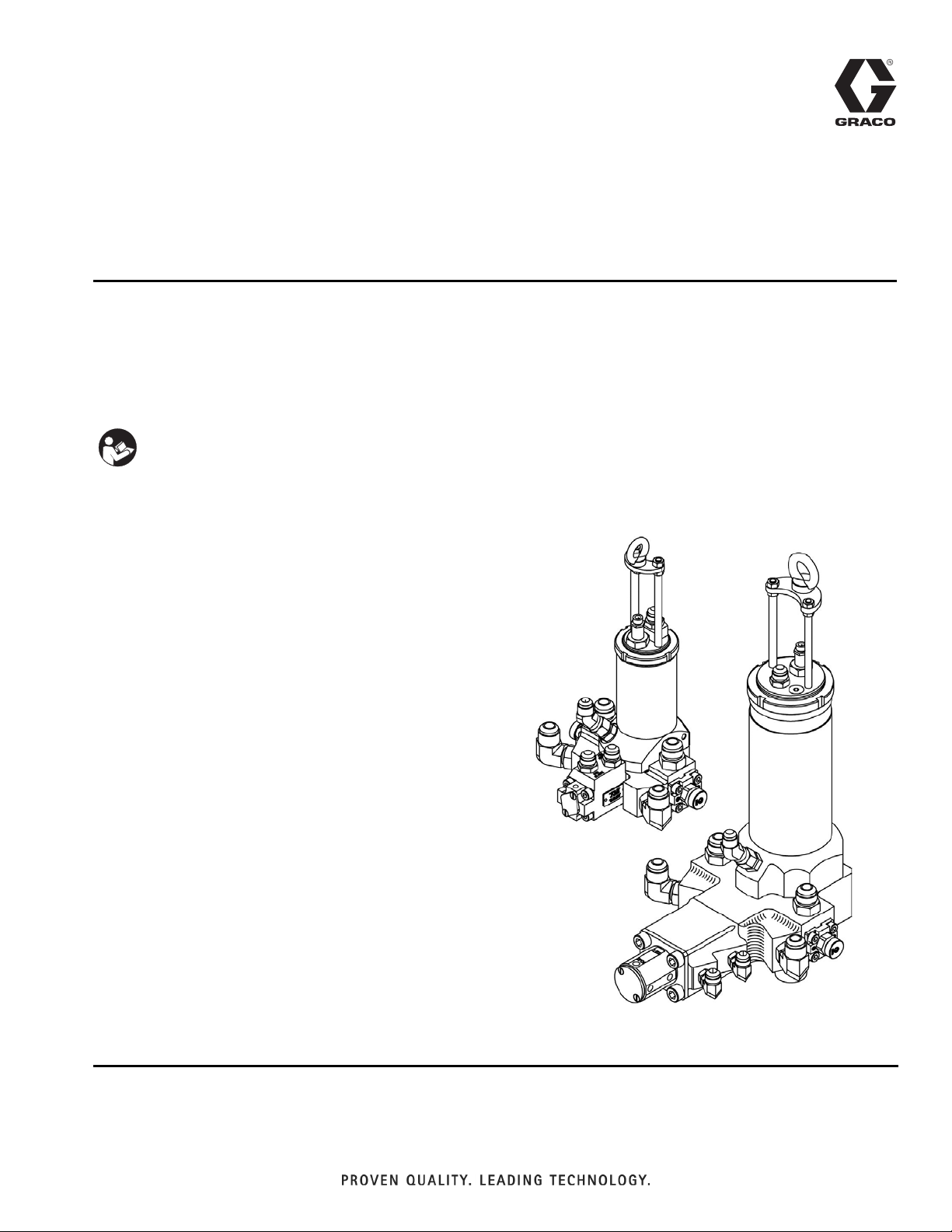
Operation - Maintenance
312753E
L-Head
For dispensing controlled ratio shots of resin and isocyanate.
3000 psi (20.6 MPa, 206 bar) Maximum Working Pressure
Important Safety Instructions
Read all warnings and instructions in this manual.
Save these instructions.
See page 2 for model information.
EN
Page 2

Models
Contents
Models . . . . . . . . . . . . . . . . . . . . . . . . . . . . . . . . . . . 2
Warnings . . . . . . . . . . . . . . . . . . . . . . . . . . . . . . . . . 3
Isocyanate Hazard . . . . . . . . . . . . . . . . . . . . . . . . . . 5
Material Self-ignition . . . . . . . . . . . . . . . . . . . . . . . . 5
Moisture Sensitivity of Isocyanates . . . . . . . . . . . . 5
Keep Components A and B Separate . . . . . . . . . . 5
Foam Resins with 245 fa Blowing Agents . . . . . . . 5
Changing Materials . . . . . . . . . . . . . . . . . . . . . . . . . 5
Component Identification . . . . . . . . . . . . . . . . . . . . 6
Installation . . . . . . . . . . . . . . . . . . . . . . . . . . . . . . . . 7
Hydraulic & Chemical Hose Installation . . . . . . . 7
Bleeding Air from Hydraulic Fluid Lines . . . . . . . 8
Maintenance . . . . . . . . . . . . . . . . . . . . . . . . . . . . . . . 9
Maintenance Schedule . . . . . . . . . . . . . . . . . . . . 9
Nozzle Grip Assembly Removal and Cleaning . 10
Nozzle Grip Assembly Installation . . . . . . . . . . . 11
Cleanout Plunger Proximity
Switch Replacement . . . . . . . . . . . . . . . . . 12
Material Plunger Proximity
Switch Replacement . . . . . . . . . . . . . . . . . 14
Cleanout Plunger Stroke Adjustment . . . . . . . . 17
Pour Nozzle Maintenance . . . . . . . . . . . . . . . . . 19
Pour Nozzle Removal and Installation . . . . . . . . 20
Step Seal and Scraper Seal Replacement . . . . 20
Troubleshooting . . . . . . . . . . . . . . . . . . . . . . . . . . . 21
Parts . . . . . . . . . . . . . . . . . . . . . . . . . . . . . . . . . . . . 24
Models 5/8, 6/10, 10/14 . . . . . . . . . . . . . . . . . . . 24
Models 13/20 and 16/25 . . . . . . . . . . . . . . . . . . 26
Orifice Kits . . . . . . . . . . . . . . . . . . . . . . . . . . . . . 28
Additional Tools and Accessories . . . . . . . . . . . 29
Technical Data . . . . . . . . . . . . . . . . . . . . . . . . . . . . 31
Graco Standard Warranty . . . . . . . . . . . . . . . . . . . 32
Graco Information . . . . . . . . . . . . . . . . . . . . . . . . . 32
Models
Maximum Working
CE
Model
20.20.5/8 ✔ 5 8 2 3000 (20.6, 206)
20.20.6/10 ✔ 6 10 2 3000 (20.6, 206)
20.20A.6/10 6 10 2 3000 (20.6, 206)
20.20.10/14 ✔ 10 14 2 3000 (20.6, 206)
20.20.13/20 ✔ 13 20 2 3000 (20.6, 206)
20.20.16/25 ✔ 16 25 2 3000 (20.6, 206)
Approved
Impingement
Chamber ID (mm)
Exiting
Chamber ID (mm)
Number of
Streams
Pressure
psi (MPa, bar)
2 312753E
Page 3
Warnings
Warnings
The following warnings are for the setup, use, grounding, maintenance, and repair of this equipment. The exclamation point symbol alerts you to a general warning and the hazard symbol refers to procedure-specific risk. Refer back
to these warnings. Additional, product-specific warnings may be found throughout the body of this manual where
applicable.
WARNING
TOXIC FLUID OR FUMES HAZARD
Toxic fluids or fumes can cause serious injury or death if splashed in the eyes or on skin, inhaled, or
swallowed.
• Read MSDS’s to know the specific hazards of the fluids you are using.
• Store hazardous fluid in approved containers, and dispose of it according to applicable guidelines.
• Always wear impervious gloves when spraying or cleaning equipment.
PERSONAL PROTECTIVE EQUIPMENT
You must wear appropriate protective equipment when operating, servicing, or when in the operating
area of the equipment to help protect you from serious injury, including eye injury, inhalation of toxic
fumes, burns, and hearing loss. This equipment includes but is not limited to:
• Protective eyewear
• Clothing and respirator as recommended by the fluid and solvent manufacturer
•Gloves
• Hearing protection
SKIN INJECTION HAZARD
High-pressure fluid from dispense valve, hose leaks, or ruptured components will pierce skin. This may
look like just a cut, but it is a serious injury that can result in amputation. Get immediate surgical
treatment.
• Do not point dispense valve at anyone or at any part of the body.
• Do not put your hand over the end of the dispense nozzle.
• Do not stop or deflect leaks with your hand, body, glove, or rag.
• Follow Pressure Relief Procedure in this manual, when you stop spraying and before cleaning,
checking, or servicing equipment.
FIRE AND EXPLOSION HAZARD
Flammable fumes, such as solvent and paint fumes, in work area can ignite or explode. To help prevent
fire and explosion:
• Use equipment only in well ventilated area.
• Eliminate all ignition sources; such as pilot lights, cigarettes, portable electric lamps, and plastic drop
cloths (potential static arc).
• Keep work area free of debris, including solvent, rags and gasoline.
• Do not plug or unplug power cords, or turn power or light switches on or off when flammable fumes
are present.
• Ground all equipment in the work area. See Grounding instructions.
• Use only grounded hoses.
• Hold gun firmly to side of grounded pail when triggering into pail.
• If there is static sparking or you feel a shock, stop operation immediately. Do not use equipment
until you identify and correct the problem.
• Keep a working fire extinguisher in the work area.
312753E 3
Page 4
Warnings
WARNING
EQUIPMENT MISUSE HAZARD
Misuse can cause death or serious injury.
• Do not operate the unit when fatigued or under the influence of drugs or alcohol.
• Do not exceed the maximum working pressure or temperature rating of the lowest rated system
component. See Technical Data in all equipment manuals.
• Use fluids and solvents that are compatible with equipment wetted parts. See Technical Data in all
equipment manuals. Read fluid and solvent manufacturer’s warnings. For complete information
about your material, request MSDS forms from distributor or retailer.
• Check equipment daily. Repair or replace worn or damaged parts immediately with genuine manufacturer’s replacement parts only.
• Do not alter or modify equipment.
• Use equipment only for its intended purpose. Call your distributor for information.
• Route hoses and cables away from traffic areas, sharp edges, moving parts, and hot surfaces.
• Do not kink or over bend hoses or use hoses to pull equipment.
• Keep children and animals away from work area.
• Comply with all applicable safety regulations.
ELECTRIC SHOCK HAZARD
Improper grounding, setup, or usage of the system can cause electric shock.
• Turn off and disconnect power at main switch before disconnecting any cables and before servicing
equipment.
• Connect only to grounded power source.
• All electrical wiring must be done by a qualified electrician and comply with all local codes and
regulations.
MOVING PARTS HAZARD
Moving parts can pinch or amputate fingers and other body parts.
• Keep clear of moving parts.
• Do not operate equipment with protective guards or covers removed.
• Pressurized equipment can start without warning. Before checking, moving, or servicing equipment,
follow the Pressure Relief Procedure in this manual. Disconnect power or air supply.
4 312753E
Page 5
Isocyanate Hazard
Isocyanate Hazard
Spraying materials containing isocyanates creates
potentially harmful mists, vapors, and atomized particulates.
Read material manufacturer’s warnings and material
MSDS to know specific hazards and precautions
related to isocyanates.
Prevent inhalation of isocyanate mists, vapors, and
atomized particulates by providing sufficient ventilation in the work area. If sufficient ventilation is not
available, a supplied-air respirator is required for
everyone in the work area.
To prevent contact with isocyanates, appropriate personal protective equipment, including chemically
impermeable gloves, boots, aprons, and goggles, is
also required for everyone in the work area.
• Keep the ISO lube pump reservoir filled with Graco
Throat Seal Liquid (TSL), Part 206995. The lubricant creates a barrier between the ISO and the
atmosphere.
• Use moisture-proof hoses specifically designed for
ISO, such as those supplied with your system.
• Never use reclaimed solvents, which may contain
moisture. Always keep solvent containers closed
when not in use.
• Never use solvent on one side if it has been contaminated from the other side.
• Always park pumps when you shutdown.
• Always lubricate threaded parts with ISO pump oil
or grease when reassembling.
Keep Components A and B Separate
Material Self-ignition
Some materials may become self-igniting if applied
too thickly. Read material manufacturer’s warnings
and material MSDS.
Moisture Sensitivity of Isocyanates
Isocyanates (ISO) are catalysts used in two component
foam and polyurea coatings. ISO will react with moisture
(such as humidity) to form small, hard, abrasive crystals,
which become suspended in the fluid. Eventually a film
will form on the surface and the ISO will begin to gel,
increasing in viscosity. If used, this partially cured ISO
will reduce performance and the life of all wetted parts.
The amount of film formation and rate of crystallization varies depending on the blend of ISO, the
humidity, and the temperature.
To prevent exposing ISO to moisture:
• Always use a sealed container with a desiccant
dryer in the vent, or a nitrogen atmosphere. Never
store ISO in an open container.
NOTICE
To prevent cross-contamination of the equipment’s
wetted parts, never interchange component A (isocyanate) and component B (resin) parts.
Foam Resins with 245 fa Blowing Agents
New foam blowing agents will froth at temperatures
above 90°F (33°C) when not under pressure, especially
if agitated. To reduce frothing, minimize preheating in a
circulation system.
Changing Materials
• When changing materials, flush the equipment multiple times to ensure it is thoroughly clean.
• Always clean the fluid inlet strainers after flushing.
• Check with your material manufacturer for chemical
compatibility.
• Most materials use ISO on the A side, but some use
ISO on the B side.
• Epoxies often have amines on the B (hardener)
side. Polyureas often have amines on the B (resin)
side.
312753E 5
Page 6
Component Identification
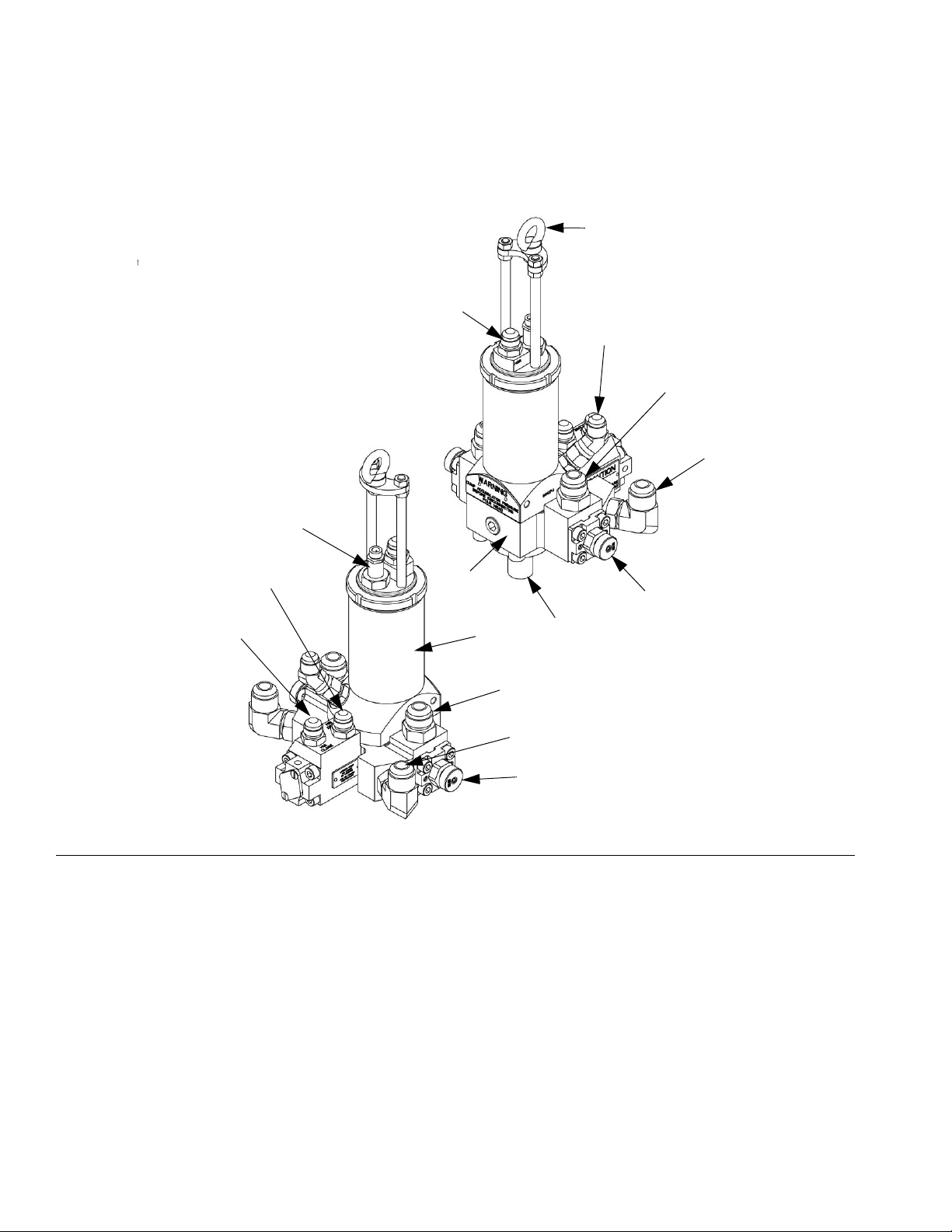
Component Identification
A
Q
B
C
D
N
FIG. 1: L-Head
Key:
AEye Bolt
B Cleanout Plunger Open Fitting
C Resin Close Fitting
D Resin Open Fitting
E Resin Nozzle Grip Assembly
F Pour Nozzle
G MixHead Body
H
P
G
E
J
F
K
L
M
H Cleanout Plunger Proximity Switch
J Cleanout Cylinder Housing
K Iso Close Fitting
L Iso Open Fitting
M Iso Nozzle Grip Assembly
N Material Plunger Close Fitting
P Material Plunger Open Fitting
Q Cleanout Plunger Close Fitting
6 312753E
Page 7
Installation
Installation
When hoisting the MixHead from an overhead position, always lift by the top eyebolt.
Handle the MixHead with care. The internal moving
parts are precisely machined for proper alignment.
Any disturbance of this alignment may result in MixHead failure.
Hydraulic & Chemical Hose Installation
Do not come into contact with Isocyanate. See Isocyanate Hazard on page 5.
NOTICE
The person performing the installation must understand the operation of the MixHead hydraulic power
source and chemical flow system.
Before disconnecting a chemical fitting or nozzle grip
assembly, turn off the proportioner, bleed the chemical pressure to ZERO, and allow the fluid to cool.
Install Hydraulic Hose
The fittings are identified on the MixHead body and the
hoses are color-coded to aid in identification and proper
installation.
When connecting the hoses, do not allow any dirt or foreign matter to enter the lines.
See FIG. 1 on page 6.
After mounting the MixHead, install the hydraulic and
chemical hoses as follows:
1. Install the hydraulic hoses for the cleanout plunger
to the fittings on the MixHead as follows:
a. Install the “close” hose to the Cleanout Plunger
Close Fitting (Q).
b. Install the “open” hose to the Cleanout Plunger
Open Fitting (B).
2. Install the hydraulic hoses for the material plunger to
the hydraulic fittings on the MixHead as follows:
a. Install the “close” hose to the Material Plunger
Close Fitting (N).
Before Disconnecting Hydraulic Fitting or
Proximity Switch
• Turn off the hydraulic pump
• Depressurize the hydraulic system
• Allow the fluid to cool
b. Install the “open” hose to the Material Plunger
Open Fitting (P).
Follow hydraulic fluid lines air purging procedure
carefully to avoid skin injection hazard.
Before Disconnecting a Chemical Fitting or
Nozzle Grip Assembly
• Turn off the proportioner
• Bleed the chemical pressure to ZERO
• Allow the fluid to cool
312753E 7
3. Purge all air from the hydraulic fluid lines using the
procedure in the Bleeding Air from Hydraulic
Fluid Lines section on page 8.
4. Manually cycle the cleanout plunger back and forth
to check for proper operation. Check for hydraulic
leaks and retighten fittings as required. Make sure
the proximity switch is securely tightened and making contact, and then return the cleanout plunger to
the “retract” position.
Page 8
Installation
5. Manually cycle the material plunger back and forth
to check for proper operation. Check for hydraulic
leaks and retighten fittings as required. Make sure
the proximity switch is securely tightened and making contact, and then return the material plunger to
the closed/recirculation position.
NOTICE
Before connecting the chemical hoses, make sure the
hydraulic hoses are properly connected and the cleanout plunger and material plunger have been tested
for proper operation. Failure to do so may result in
chemical cross-contamination of the MixHead and
proportioning system.
6. Install the chemical hoses to the fittings on the MixHead as follows:
a. Install the isocyanate “close” hose to the Iso
Close Fitting (K).
b. Install the isocyanate “open” hose to the Iso
Open Fitting (L).
c. Install the resin “close” hose to the Resin Close
Fitting (C).
4. Use a bucket to catch the hydraulic fluid, and lay
down a drop cloth to catch spilled hydraulic fluid.
The hydraulic fluid motor must be off and the manual
unloading valve must be completely open before proceeding to the next step to avoid high pressure
spraying of hydraulic fluid.
5. At the “close” port of the material plunger (N),
loosen the hydraulic hose very slowly, allow all pressurized air to escape, then tighten the hose.
6. Move the cleanout plunger to the “extend” position.
At the “close” port of the cleanout plunger (Q),
loosen the hydraulic hose very slowly, allow all pressurized air to escape, then tighten the hose.
7. Move the cleanout plunger to the “retract” position.
At the “open” port of the cleanout plunger (B),
loosen the hydraulic hose very slowly, allow all pressurized air to escape, and then tighten the hose.
Install Chemical Hose
d. Install the resin “open” hose to the Resin Open
Fitting (D).
7. Recirculate both chemical lines until the pressures
stabilize.
8. Pressurize the MixHead and check for chemical
leaks.
Bleeding Air from Hydraulic Fluid Lines
1. Start the hydraulic fluid motor to build pressure in
the hydraulic lines.
2. Turn off the hydraulic fluid motor.
3. Open the manual unloading valve all the way.
An assistant is required for the following steps.
8. With the cleanout plunger in the “retract” position,
open the material plunger by manually energizing
the hydraulic directional valve.
9. Have an assistant bleed out any air at the “open”
port of the material plunger (P).
10. Hold the material plunger in the open/pour position
until the “open” port has been completely bled of air
and the hydraulic hose has been securely tightened,
then return the material plunger to the closed position.
8 312753E
Page 9
Maintenance
All maintenance must be done with pressure relieved
and the power switched off and locked out, unless
otherwise noted.
Maintenance Schedule
Service Action Frequency Reference
Maintenance
Apply cleanout plunger lubrication Flush mesamoll into the
cleanout bore
Inspect for hydraulic and chemical
leaks
Inspect proximity switch wires for
open exposure
Inspect pour nozzle bore Clean as needed Weekly See page 20
Inspect adjustment stem, injection
nozzle, and nozzle grip for blockage
and erosion
Replace seals as needed Daily See page 7
Replace cord set/switch as
needed
Replace parts as needed Weekly See page 10
Daily See page 20
Weekly See pages 12, 14
312753E 9
Page 10
Maintenance
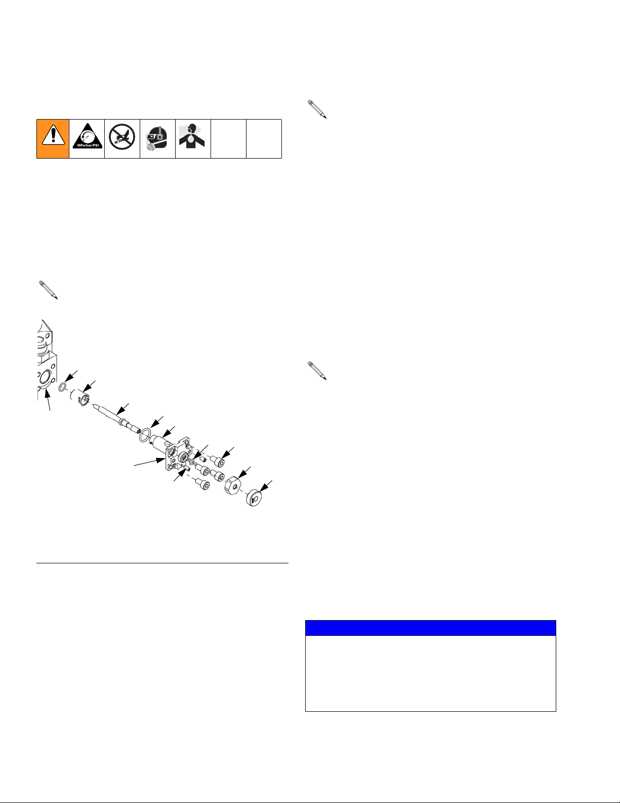
Nozzle Grip Assembly Removal and Cleaning
The nozzle grip assembly must be removed, disassembled and cleaned whenever disconnecting the chemical
hoses, replacing the internal o-rings, and/or changing
the injection nozzle and adjustment stem. It is advisable
to maintain a supply of spare nozzle grips, adjustment
stems, hex o-ring seats, locknuts, and the necessary
screws and o-rings.
See Parts List on page 25.
3
18
Nozzle Grip Assembly for models
5/8, 6/10, 10/14 shown
Tools Required
See Additional Tools and Accessories on
page 29.
• Nozzle ejector
• 5/32 in. hex key
• M3 hex key for M6 set screws
• 1 in. open-end wrench
• Torque wrench with M6 hex for M8 SHC screws
Nozzle Grip Removal
1. Bleed all chemical pressures to zero.
2. Remove one of the M8 socket head cap screws (13)
from the nozzle grip assembly and reinsert it at least
two full turns.
This screw is a safety stop for the nozzle grip
should any pressure be left in the system.
17
FB
FA
Key:
FA Roll Pin (pressed into nozzle grip, not shown)
FB Slot for roll pin
IG. 2:
F
2
9
4
14
13
3. Unscrew the other three M8 screws (13) from the
nozzle grip. Try pulling and pushing the assembly in
and out of its bore to ensure that no pressure exists.
5
6
a. If it will not come out, turn the two M6 set
screws (14) contained in the nozzle grip clockwise to separate it.
b. If the nozzle grip assembly will not come out
with the set screws fully extended into the MixHead body, replace the M6 set screws (14) with
longer M6 cap screws, and continue to move
the nozzle grip assembly out of the MixHead
body with the cap screws until the nozzle grip
assembly can be removed by hand.
NOTICE
Whenever a chemical hose is disconnected, immediately remove its associated nozzle grip assembly and
flush all chemical from the assembly and the MixHead
bore. Exposure to atmospheric moisture will cause
the remaining chemical in the nozzle grip assembly to
harden, making removal from the MixHead difficult.
10 312753E
Page 11

Maintenance
4. Using a clockwise twisting motion, pull the entire
nozzle grip assembly out of the MixHead body.
5. If the injection nozzle will not come out with the nozzle grip assembly, use the nozzle ejector tool to
remove the injection nozzle. See Additional Tools
and Accessories on page 29.
Nozzle Grip Cleaning
6. Flush remaining chemical and dirt from the nozzle
grip bore and mating surface of the MixHead body.
7. Disassemble the nozzle grip assembly and soak the
metal parts in solvent.
8. Clean the parts thoroughly,
9. Inspect for damage and/or wear and replace as
required.
10. Inspect the three o-rings (2, 3, 4) and replace as
required.
Nozzle Grip Assembly Installation
6. With the roll pin (FA) on the nozzle grip (9) in place
and lined up with the slot (FB) in the MixHead body,
insert the nozzle grip into the MixHead body.
7. Install the four M8 screws (13) hand tight.
8. Use a torque wrench to alternately tighten each
screw 1/2 turn at a time to 180 in-lb of torque.
The roll pin in the nozzle grip allows only one
method of insertion, ensuring that the chemical
openings in the nozzle grip and MixHead body will
be correctly aligned. Do not insert a nozzle grip
without the roll pin in place, or the nozzle grip may
be installed upside down in the body, causing the
chemical entering the MixHead to accumulate at
the nozzle grip and clog it.
9. Thread the two set screws (14) into the nozzle grip
until the screws contact the MixHead body.
10. Apply Lubriplate grease to the small o-ring (4) and
insert it into the nozzle grip (9).
11. Install and tighten down the hex o-ring seat (5) onto
the nozzle grip (9).
12. Install and hand tighten the locknut (6).
13. Recirculate all chemical lines until the pressures
stabilize.
See FIG. 2 on page 10.
With all parts clean and dry, assemble and install the
nozzle grip assembly as follows.
1. Lightly coat the injection needle (17) with Lubriplate
grease. Screw the injection needle (17) into the nozzle grip (9) until the shoulder of the injection needle
bottoms out in the nozzle grip counterbore.
2. Lightly coat the medium o-ring (3) with Lubriplate
grease and install on the end of the injection
nozzle (18).
3. Mount the injection nozzle (18) on the nozzle
grip (9).
4. Lightly coat the large o-ring (2) with Lubriplate
grease and install on the nozzle grip (9).
5. Lubricate the nozzle grip (9) with Lubriplate grease.
14. Pressurize the MixHead and check for chemical
leaks.
15. Set the desired impingement pressure.
a. Loosen the locknut.
b. Turn the adjustment stem until the desired
impingement pressure is achieved.
c. Retighten the locknut.
312753E 11
Page 12

Maintenance
Cleanout Plunger Proximity Switch Replacement
• Do not operate the MixHead unless all proximity
switches are in place and the proximity switch
alarm is operational and armed.
• A shock hazard or unpredictable machine operation
could occur if the proximity switch is separated from
its mating cord set, or if either the proximity switch
or its mating cord set are used with a different
switch or cord set.
The proximity switch on the cleanout plunger is a
high-pressure switch that extends directly into the
hydraulic fluid. The quick-disconnect feature on the
switch allows easy replacement of a failed or damaged
switch or cord set.
Tools Required
• 1 in. open-end wrench
Cord Set Replacement
See FIG. 3 on page 12.
1. Disconnect the cord set (BA) from the machine at
the Amphenol connector (BB).
2. Unscrew the knurled knob at the end of the cord
set (BA) and disconnect the cord set from the proximity switch (BC) on the MixHead.
3. Match up the keys on the cord set (BA) with the keyways on the proximity switch (BC), insert the cord
set into the proximity switch, and tighten the knurled
knob.
4. Connect the cord set (BA) to the machine at the
Amphenol connector (BB).
F
IG. 3
BA
BB
BC
BD
Key:
BA Proximity Switch Cord Set
BB Amphenol
BC Cleanout Plunger Proximity Switch
BD O-ring
®
Connector
12 312753E
Page 13

Proximity Switch Replacement
See FIG. 3 on page 12.
1. Turn OFF the hydraulic fluid motor, bleed the
hydraulic pressure to zero and allow the fluid to
cool.
2. Disconnect the cord set (BA) from the machine at
the Amphenol connector (BB).
3. Unscrew the knurled knob at the end of the cord
set (BA) and disconnect the cord set from the proximity switch (BC) on the MixHead.
4. Unscrew the proximity switch (BC) from the MixHead using the open-end wrench.
5. The replacement proximity switch will have an
o-ring (BD) already in position. Be sure to install the
switch (BC) with the o-ring (BD) in place.
Maintenance
6. Carefully screw the replacement proximity switch
(BC) back into the MixHead by hand and tighten
with the wrench.
7. Ensure the o-ring (BD) forms a leak-proof seal.
8. Match the keys on the cord set with the keyways on
the proximity switch, insert the cord set into the
proximity switch and tighten the knurled knob.
9. Connect the cord set (BA) to the machine at the
Amphenol connector (BB).
10. Purge all air from the hydraulic fittings. See step 3
on page 7.
312753E 13
Page 14

Maintenance
Material Plunger Proximity Switch Replacement
Do not operate the MixHead unless all proximity
switches are in place and the proximity switch alarm
is operative and armed.
Tools Required
• M2.5 hex key for M4 flat head screws
• Metric wrench (13mm)
• Proximity Switch gauge
• Gauge M1978-1: Models 5/8, 6/10, 10/14
• Gauge MU1140: Models 13/20, 16/25
See FIG. 4 on page 15 for models 5/8, 6/10, and
10/14. See F
16/25.
1. Turn OFF the hydraulic fluid motor and chemical
motor.
2. Disconnect the old proximity switch (CA, DA) from
the machine at the Amphenol connector.
3. Remove the two M4 flat head screws from the cover
plate on the material plunger housing (CH) or sensor cap (DH), depending on which model you have.
Remove the cover plate. Wipe the inside bore clean
of any dirt and hydraulic oil.
4. The position of the material plunger (CG, DF) can
be determined by observing its relationship to the
proximity switch within the material plunger housing/sensor cap. The material plunger will be in a
sensing position for the open/pour position, and in a
non-sensing position for the closed/recirculation
position.
5. While holding the conduit (CB, DB) of the old proximity switch stationary with one hand, loosen the
adapter (CC, DC) from the jam nut (CE, DD) with
the other hand. Loosen the jam nut and
lock-washer (CD, DE) on the proximity switch from
the material plunger housing/sensor cap. Remove
the proximity switch by unscrewing it from the
tapped hole.
IG. 5 on page 16 for models 13/20 and
6. Insert the sensor gauge (CF, DG) into the material
plunger housing/sensor cap.
7. Install the replacement proximity switch into the
appropriate threaded hole in the material plunger
housing/sensor cap as follows.
Models 5/8, 6/10, 10/14:
See FIG. 4 on page 15.
a. Thread the replacement proximity switch (CA)
until it contacts the flat cutout on the sensor
gauge (CF).
b. Maintain this position by tightening the
lock-washer (CD) and jam nut (CE) on the
threads of the proximity switch against the
material plunger housing (CH), with the
lock-washer between the jam nut and the material plunger housing.
c. While holding the conduit (CB) stationary,
tighten the adapter (CC) by hand until it contacts the jam nut (CE).
d. Remove the sensor gauge (CF) from the mate-
rial plunger housing (CH).
e. This step will ensure a clearance of
0.010-0.015 in. (0.254-0.381 mm) between the
material plunger (CG) and proximity
switch (CA).
Models 13/20 and 16/25:
See FIG. 5 on page 16.
a. Thread the replacement proximity switch (DA)
into the sensor cap (DH) until it contacts the
outer diameter of the sensor gauge (DG).
b. Maintain this position by tightening the lock
washer (DE) and jam nut (DD) on the threads of
the proximity switch against the sensor cap, with
the lock washer between the jam nut and the
sensor cap.
14 312753E
Page 15

Maintenance
c. While holding the conduit (DB) stationary,
tighten the adapter (DC) by hand until it contacts the jam nut (DD).
d. Remove the sensor gauge (DG) from the sen-
sor cap (DH).
e. This step will ensure a clearance of
0.010-0.015 in. (0.254-0.381 mm) between the
material plunger (DF) and proximity switch (DA).
8. Reinstall the cover plate to the material plunger
housing/sensor cap using the two M4 flat head
screws.
9. Connect the proximity switch to the machine at the
Amphenol connector.
1
CF
CA
CC
CD
CB
CE
1
Set Proximity Switch to make contact here on models 5/8, 6/10, 10/14.
2
0.010-0.015 in. (0.254-0.381 mm)
FIG. 4: Material Proximity Switch - Models 5/8, 6/10, 10/14
2
CG
CH
Key:
CA Proximity Switch
CB Conduit
CC Adapter
CD Lock-washer
CE 8 mm Jam Nut
312753E 15
CF Sensor Gauge M1978-1
CG Material Plunger
CH Material Plunger Cylinder Housing
Page 16

Maintenance
DF
DA
1
DC
DE
DB
DD
1
0.010-0.015 in. (0.254-0.381 mm)
FIG. 5: Material Proximity Switch - Models 13/20 and 16/25.
Key:
DA Proximity Switch
DB Conduit
DC Adapter
DD 8 mm Jam Nut
DE Lock-washer
DF Material Plunger
DG Sensor Gauge MU1140
DH Sensor Cap
DG
DH
16 312753E
Page 17

Cleanout Plunger Stroke Adjustment
The cleanout plunger stroke is properly set during factory assembly so that the cleanout plunger completely
clears the impingement chamber during a pour. Usually,
no adjustment is needed. However, for some applications where the chemical flow is on the lower end of the
MixHead flow range, improved mixing may be achieved
by adjusting the cleanout plunger so that it partially
blocks the impingement chamber leading into the exiting
chamber.
Tools Required
•Steel rod
• Hook spanner wrench
3. Loosen the shaft nut from the cylinder housing by
Maintenance
In the following step, there must be no hydraulic pressure in the system when loosening the shaft nut from
the cylinder housing.
turning counterclockwise with the proper hook spanner wrench.
Adjusting Plug
Shaft Nut
• Wrench MU1063: Models 5/8, 6/10, 10/14
• Wrench MU1080: Models 13/20 and 16/25
1. Relieve hydraulic pressure to zero and allow the
fluid to cool.
2. Record the original position of the adjusting plug in
relationship to the cylinder housing. This is done to
establish a reference point for restoring the cleanout
plunger to its original setting and for determining the
position of the cleanout plunger relative to the
impingement chamber.
a. Accurately measure and record the distance
that the adjusting plug extends above the shaft
nut.
b. Record the number of exposed threads of the
adjusting plug.
Adjusting
Plug
NOTICE
In the following step, do not exceed the following number of complete revolutions of the adjusting plug from
its original factory setting:
• Models 20.20.5/8 and 20.20.6/10: One
• Models 20.20.10/14: Two
• Models 20.20.13/20: Three
• Models 20.20.16/25: Four
Exceeding the above limits may result in chemical
cross-contamination of the MixHead due to complete
blockage of the impingement chamber.
Shaft Nut
312753E 17
Page 18

Maintenance
4. Place the steel rod between the two tie rods on top
of the adjusting plug and carefully turn the adjusting
plug clockwise to a desired position within the range
listed above. One complete turn moves the adjusting plug 0.078 in. (1.9812 mm).
5. Lock the adjusting plug into position by tightening
the shaft nut against the cylinder housing with a
hook spanner.
6. Purge all air from the hydraulic fittings. See step 3
on page 7.
18 312753E
Page 19

Maintenance
Pour Nozzle Maintenance
With proper maintenance, the L-Head is capable of performing thousands of pours without the need for removing and cleaning the pour nozzle. However, the use of
fast-reacting chemicals will require more frequent pour
nozzle removal and cleaning. The faster the chemical
reaction, the more frequent the need to clean the pour
nozzle. This is due to hardening of the chemicals before
the cleanout plunger can clean the bore. A sticking cleanout plunger is a good indication that the pour nozzle
must be cleaned. Use the following maintenance practices to help minimize cleanout plunger sticking:
Cleanout Plunger Lubrication
If the MixHead is to be left idle for any period of time, the
cleanout plunger should be lubricated before leaving.
1. Retract the cleanout plunger to the open/pour position.
Cleanout Plunger Retract Routine
During operation, periodic lubrication with mesamoll
may be all that is required to prevent sticking. However,
in cases where sticking is a continual problem, the cleanout plunger retract routine may be utilized.
In the retract routine, the cleanout plunger is retracted
as soon as it is permissible after each shot, to ensure
that the scraper seal has a chance to remove the foam
from the cleanout plunger while the foam is still wet.
Contact Graco technical service to learn more about the
cleanout plunger retract routine. Some modifications to
the software timing are required to incorporate this procedure.
2. Run a fine-grade wire brush up and down the cleanout bore to remove any loose foam.
3. Bring the cleanout plunger to the closed position,
and completely submerge the pour nozzle in a cup
of mesamoll plasticizer.
4. Cycle the cleanout plunger.
5. The mesamoll will be sucked up into the MixHead,
providing the lubrication between the cleanout
plunger and the bore it rides in.
6. Cycle the cleanout plunger several more times to
ensure that all of the remaining foam is removed,
and then leave the cleanout plunger in the
open/pour position.
312753E 19
Page 20

Maintenance
Pour Nozzle Removal and Installation
Tools Required
• Torque wrench with M6 and M8 sockets
• Fine-grade wire brushes on air tool
1. Cycle the cleanout plunger to the open/pour position.
2. Remove the socket head cap screws holding the
pour nozzle to the MixHead body, and remove the
nozzle. If there is resistance, lightly tap the nozzle
with a soft hammer until it breaks free from the MixHead body.
3. Thoroughly clean the external surface and the bore
of the pour nozzle of all foam and foreign matter
using fine grade wire brushes. Soak the nozzle in
solvent if necessary.
Step Seal and Scraper Seal Replacement
NOTICE
Do not attempt to replace the step seal and/or scraper
seal yourself.
Replacement of the step seal and the scraper seal
should be considered only when a hydraulic leak develops out of the pour nozzle, or when an excessive
amount of foam is getting into the hydraulics of the cleanout plunger.
MixHeads requiring step seal and/or scraper seal
replacement must be returned to Graco for rebuilding.
4. Thoroughly clean the external mounting surface of
the MixHead body using fine grade wire brushes.
Cycle the cleanout plunger forward to the
closed/non-pour position.
5. Carefully install the pour nozzle onto the cleanout
plunger and into position on the MixHead body.
Install and finger-tighten the screws. Cycle the cleanout plunger several times to ensure proper alignment of the pour nozzle. Leave the cleanout plunger
in the closed/non-pour position after cycling.
NOTICE
Proper alignment of the cleanout plunger within the
bore of the pour nozzle is critical to the life of the MixHead.
6. Using a torque wrench, alternately tighten the three
socket head cap screws a half-turn at a time to
180 in-lb.
20 312753E
Page 21

Troubleshooting
Troubleshooting
Any individual working with the equipment must be
knowledgeable in the necessary safety procedures.
Unless otherwise noted, all electrical troubleshooting
must be done with the incoming power switched off
and locked out at the source.
Symptom Probable Cause(s) Corrective Actions Reference
Chemical Crossover Seal failure on Material
Plunger
Fracture of Material
Plunger
Cleanout Plunger did not
retract during pour
Improper customer adjustment on stroke of Cleanout
Plunger
Hydraulic leak out of Pour
Nozzle
Chemical leak out of Pour
Nozzle
Galled Cleanout Plunger Send in MixHead for repair
Worn Step Seal Send in MixHead for repair
Worn Seal on Material
Plunger
Fractured Tip on Material
Plunger
Cleanout Proximity Switch
Damaged Switch Remove and test Switch
not working
Damaged Cord Set Remove and test Cord Set
Material Proximity Switch
Damaged Switch Remove and test Switch
not working
Improper clearance
between Switch and Material Plunger
Cleanout Plunger sticks in
bore
Poor lubrication maintenance of Cleanout Plunger
Build-up of foam in Pour
Nozzle
Galled Cleanout Plunger Send in MixHead for repair
Foam is curing on Cleanout Plunger before
scraper seal can remove it
Send in MixHead for repair
Send in MixHead for repair
Send in MixHead for repair
Send in MixHead for repair
Send in MixHead for repair
Send in MixHead for repair
Replace as needed
Replace as needed
Replace as needed
Reset clearance using sensor gauge
Lubricate Cleanout
Plunger on a daily basis
Remove and clean Pour
Nozzle
Try Plunger Retract Routine
See page 12
See page 12
See page 14
See page 14
See page 20
See page 20
Contact Graco
312753E 21
Page 22

Troubleshooting
Symptom Probable Cause(s) Corrective Actions Reference
Hydraulic leak around
Cleanout Plunger Proximity
Switch
Hydraulic leak out of sensing area of Material
Damaged o-ring Replace o-ring See page 12
Proximity Switch not tightened down onto Adjusting
plug
Improper sealing Replace with Polypak seal
Tighten Proximity Switch
against Adjusting Plug to
compress seal
See page 12
Contact Graco
and modify Sensor Cap
Plunger
Chemical leak out of Nozzle Grip Assembly
Cleanout Plunger falls out Fractured Cleanout
Loose Hex o-ring Seat Replace o-ring See Maintenance, page 9.
Damaged o-ring Seat Replace o-ring(s) See Maintenance, page 9.
Send in MixHead for repair
Plunger
Excessive amount of foam
in hydraulics
Worn Scraper Seal Send in MixHead for repair
Badly scored or galled
Send in MixHead for repair
Cleanout Plunger
Chemical pressure rise
during pour- one side only
Incorrect orifice size of
Injection Nozzle
Partial blockage in orifice
Replace with proper orifice
See page 10
size(s)
Remove blockage See page 10
of Injection Nozzle
Partial blockage in Nozzle
Remove blockage See page 10
Grip
Incorrect Injection Nozzle/Adjustment Stem size
Use matching Nozzle and
Stem sizes
See Technical Data,
page 31
combination
Chemical pressure rise
during pour- both sides
Chemical pressure drop
during pour- one or both
Cleanout Plunger partially
blocking impingement
chamber
Runner and/or Aftermixer
too small
Restriction exists in return
loop from MixHead to Tank
Adjust Cleanout Plunger
stroke to clear impingement chamber
Enlarge Runner and/or
Aftermixer
Remove restriction in
return loop
See page 17
sides
Injection Nozzle stuck in
body
Exposure to air has hardened chemical remaining
Remove Injection Nozzle
using nozzle ejector tool
See page 10
around Injection Nozzle
Mounting Holes stripped
out of body
Chemical or hydraulic leak
around fitting
Erosion of Adjustment
Stem Tip and Orifice of
Injection Nozzle
Poor quality foam at lower
output
Incorrect mounting of Mix-
Send in MixHead for repair
Head
Damaged o-ring Replace o-ring
Damaged fitting Replace fitting
Chemical attack of steel
parts or wear by abrasive
Replace with Carbide
Adjustment Stems and
Injection Nozzles
Incorrect Orifice size of
Injection Nozzle
Approaching lower limit of
MixHead throughput
Replace with smaller Orifice size
Adjust stroke of Cleanout
Plunger
See page 10, and Techni -
cal Data on page 31
See page 24
See page 24
22 312753E
Page 23

Troubleshooting
312753E 23
Page 24

Parts
Parts
Models 5/8, 6/10, 10/14
10
11
16
15
1
3
18
17
2
7
8
12
14
9
4
13
5
6
24 312753E
Page 25

Parts List
Ref. Part No. Description Qty
1 0135-910 O-RING 1
2*† --- O-RING 1
3*† --- O-RING 1
4*† --- O-RING 1
5 M0450 SEAT, hex o-ring 1
6 M0454-2 LOCKNUT 1
7 M362-3 COVER, sensor 1
8---
---
---
--9 M1051-1 GRIP, nozzle 1
10 M24017 SWITCH, material plunger proximity 1
11 M24022 CORD SET, cleanout plunger proximity switch 1
12 MA1009 SCREW, socket head cap 3
13 MA1755 SCREW, socket head cap 4
14 MA1759 SCREW, socket head cap 2
15 MA1769 SCREW, flat head machine 2
16 MS4086 SWITCH, cleanout plunger proximity 1
17† --- NEEDLE, injection, L style 1
18† --- NOZZLE, L Injection 1
NOZZLE, pour (20.20.5/8)
NOZZLE, pour (20.20.6/10)
NOZZLE, pour (20.20A.6/10)
NOZZLE, pour (20.20.10/14)
Parts
1
1
1
1
* Part included in Nozzle Grip Assembly Seal Kit MK1490, which can be purchased separately.
† Part included in Orifice Kits listed on page 28.
--- Parts not available for individual sale.
312753E 25
Page 26

Parts
Models 13/20 and 16/25
110
111
116
101
115
107
108
112
103
118
117
102
114
109
104
113
105
106
26 312753E
Page 27

Parts List
Ref Part No. Description Qty
101 0135-910 O-RING 1
102*† --- O-RING 1
103*† --- O-RING 1
104*† --- O-RING 1
105 M0450 SEAT, hex o-ring 1
106 M0454-2 LOCKNUT 1
107 M375-3 COVER, sensor 1
108 ---
--109 M1051-1 GRIP, nozzle 1
110 M24017
M24018
111 M24022 CORD SET, cleanout plunger proximity switch 1
112 MA1800 SCREW, socket head cap 4
113 MA1755 SCREW, socket head cap 4
114 MA1759 SCREW, socket head cap 2
115 MA1769 SCRW, flat head machine 2
116 MS4086 SWITCH, cleanout plunger proximity 1
117† --- NEEDLE, injection, L style 1
118† --- NOZZLE, L Injection 1
NOZZLE, pour (13/20)
NOZZLE, pour (16/25)
SWITCH, material plunger proximity (male)
SWITCH, material plunger proximity (female)
Parts
1
1
1
1
* Parts included in Nozzle Grip Assembly Seal Kit MK1490, which can be purchased separately.
† Part included in Orifice Kits listed on page 28.
--- Parts not available for individual sale.
312753E 27
Page 28

Parts
Orifice Kits
EB
EC
Key:
EA L-injection Nozzle
EB L-style Injection Needle
EC O-ring
ED O-ring, fluoroelastomer
EE O-ring, fluoroelastomer
F
IG. 6: L-Head Orifice Kit
Kit Numbers
Orifice size (mm) Kit
Calibrate M0934A-4
0.25 247761
0.45 247762
0.5 247763
0.75 247764
0.80 247765
0.85 247766
1.00 247767
1.10 247811
1.20 247848
1.25 247858
1.30 247859
1.40 247860
1.50 247861
1.60 247862
1.65 247863
1.70 247864
1.75 247865
1.80 247866
1.90 247867
2.00 247868
2.40 247869
3.20 247870
3.60 247871
4.20 247872
5.00 247873
5.60 247874
ED
EA
EE
Orifice Selection
This section is provided to give an approximate orifice size needed for a given application. There is no
guarantee that this formula will give you the correct
orifice.
To help choose the correct orifice for your application,
use the following equation to find a suggested ‘effective’
orifice size.
D F 0.324⁄()P Sg 62.4××()×=
D = Orifice Diameter (mm)
F = Flow through orifice (pounds / second)
P = Dispensing Pressure for Chemical (psi)
Sg = Specific Gravity of Chemical
The calculated “D” is the suggested orifice size in millimeters. Round to the nearest available orifice size to get
the suggested orifice for the application.
28 312753E
Page 29

Additional Tools and Accessories
Part No. Description Qty
MU1079 EJECTOR, nozzle 1
M1978-1* GAUGE, sensor (5/8, 6/10, 10/14) 1
MU1140† GAUGE, sensor (13/20, 16/25) 1
MU1063* WRENCH, hook spanner (5/8, 6/10, 10/14) 1
MU1080† WRENCH, hook spanner (13/20, 16/25)) 1
MU1064*† HEX L-KEY, 3 mm, long arm 1
MU1066*† HEX L-KEY, 6mm, long arm 1
MU1069*† HEX KEY, 5/32 in., 6 in. 1
MU1154*† HEX L-KEY, 3/8 in., long arm 1
MU1155*† WRENCH, open end, 1 in., 15 deg 1
MU1067† HEX L-KEY, 8 mm, long arm 1
* Included in L-Head Tool Kit MK1184 for models 5/8,
6/10, and 10/14. Kit can be purchased separately
† Included in L-Head Tool Kit MK1223 for models 13/20
and 16/25. Kit can be purchased separately
Parts
312753E 29
Page 30

Parts
30 312753E
Page 31

Technical Data
Technical Data
Proximity Switch Electrical Requirements . . . . Cleanout Piston: 50 mA @24VDC
Material Piston: 60 mA @ 16 VDC
Fittings (See F
Max Weight. . . . . . . . . . . . . . . . . . . . . . . . . . . . 43 lb (19.5 kg)
Wetted Parts. . . . . . . . . . . . . . . . . . . . . . . . . . . Stainless Steel, Trivalent Chromium Plated Carbon Steel,
IG. 1 on page 6) . . . . . . . . . . . . . Iso Close Fitting (K):
1/2 BSPP X 1-1/16 JIC CONNECT,
1-1/16-12 F JIC x 3/4-16 JIC
Resin Close Fitting (C):
1/2 BSPP X 1-1/16 JIC CONNECT,
1-1/16-12 F JIC x 7/8-14 JIC
Iso Open Fitting (L):
1/2 BSPP x 1-1/16-12 ELBOW,
1-1/16-12 F JIC x 3/4-16 JIC
Resin Open Fitting (D):
1/2 BSPP x 1-1/16-12 ELBOW,
1-1/16-12 F JIC x 7/8-14 JIC
Cleanout Plunger Open Fitting (B):
3/8 BSPP x 3/4-16 JIC NIPPLE,
3/4-16 JIC x 3/4-16 JIC (SW) 45
PTFE, Perifluorinated and EPDM O-rings
312753E 31
Page 32

Graco Standard Warranty
Graco warrants all equipment referenced in this document which is manufactured by Graco and bearing its name to be free from defects in
material and workmanship on the date of sale to the original purchaser for use. With the exception of any special, extended, or limited warranty
published by Graco, Graco will, for a period of twelve months from the date of sale, repair or replace any part of the equipment determined by
Graco to be defective. This warranty applies only when the equipment is installed, operated and maintained in accordance with Graco’s written
recommendations.
This warranty does not cover, and Graco shall not be liable for general wear and tear, or any malfunction, damage or wear caused by faulty
installation, misapplication, abrasion, corrosion, inadequate or improper maintenance, negligence, accident, tampering, or substitution of
non-Graco component parts. Nor shall Graco be liable for malfunction, damage or wear caused by the incompatibility of Graco equipment with
structures, accessories, equipment or materials not supplied by Graco, or the improper design, manufacture, installation, operation or
maintenance of structures, accessories, equipment or materials not supplied by Graco.
This warranty is conditioned upon the prepaid return of the equipment claimed to be defective to an authorized Graco distributor for verification of
the claimed defect. If the claimed defect is verified, Graco will repair or replace free of charge any defective par ts. The equipment will be returned
to the original purchaser transportation prepaid. If inspection of the equipment does not disclose any defect in material or workmanship, repairs will
be made at a reasonable charge, which charges may include the costs of parts, labor, and transportation.
THIS WARRANTY IS EXCLUSIVE, AND IS IN LIEU OF ANY OTHER WARRANTIES, EXPRESS OR IMPLIED, INCLUDING BUT NOT LIMITED
TO WARRANTY OF MERCHANTABILITY OR WARRANTY OF FITNESS FOR A PARTICULAR PURPOSE.
Graco’s sole obligation and buyer’s sole remedy for any breach of warranty shall be as set forth above. The buyer agrees that no other remedy
(including, but not limited to, incidental or consequential damages for lost profits, lost sales, injury to person or property, or any other incidental or
consequential loss) shall be available. Any action for breach of warranty must be brought within two (2) years of the date of sale.
GRACO MAKES NO WARRANTY, AND DISCLAIMS ALL IMPLIED WARRANTIES OF MERCHANTABILITY AND FITNESS FOR A
PARTICULAR PURPOSE, IN CONNECTION WITH ACCESSORIES, EQUIPMENT, MATERIALS OR COMPONENTS SOLD BUT NOT
MANUFACTURED BY GRACO. These items sold, but not manufactured by Graco (such as electric motors, switches, hose, etc.), are subject to
the warranty, if any, of their manufacturer. Graco will provide purchaser with reasonable assistance in making any claim for breach of these
warranties.
In no event will Graco be liable for indirect, incidental, special or consequential damages resulting from Graco supplying equipment hereunder, or
the furnishing, performance, or use of any products or other goods sold hereto, whether due to a breach of contract, breach of warranty, the
negligence of Graco, or otherwise.
FOR GRACO CANADA CUSTOMERS
The Parties acknowledge that they have required that the present document, as well as all documents, notices and legal proceedings entered into,
given or instituted pursuant hereto or relating directly or indirectly hereto, be drawn up in English. Les parties reconnaissent avoir convenu que la
rédaction du présente document sera en Anglais, ainsi que tous documents, avis et procédures judiciaires exécutés, donnés ou intentés, à la suite
de ou en rapport, directement ou indirectement, avec les procédures concernées.
Graco Information
For the latest information about Graco products, visit www.graco.com.
TO PLACE AN ORDER, contact your Graco distributor or call to identify the nearest distributor.
Phone: 612-623-6921 or Toll Free: 1-800-746-1334 Fax: 330-966-3006
All written and visual data contained in this document reflects the latest product information available at the time of publication.
GRACO INC. AND SUBSIDIARIES • P.O. BOX 1441 • MINNEAPOLIS MN 55440-1441 • USA
Copyright 2008, Graco Inc. All Graco manufacturing locations are registered to ISO 9001.
Graco reserves the right to make changes at any time without notice.
For patent information, see www.graco.com/patents.
Original instructions. This manual contains English. MM 312753
Graco Headquarters: Minneapolis
International Offices: Belgium, China, Japan, Korea
www.graco.com
Revised June 2013
 Loading...