

Page 1
Instructions - Parts
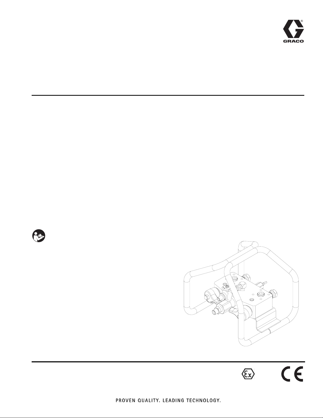
XM Mix Manifold Kits
For mixing two component reactive materials with XM plural-component sprayers.
Not for use on mechanical proportioners.
Approved for use in explosive atmospheres.
For professional use only.
312749G
Part No. 255684
Mix Manifold
Part No. 256980
Remote Mix Manifold Conversion Kit with protective guard
7250 psi (50 MPa, 500 bar) Maximum Working Pressure
160°F (71°C) Maximum Fluid Temperature
Important Safety Instructions
Read all warnings and instructions in this manual.
Save these instructions.
Mix Manifold and Remote Mix Manifold
Conversion Kit
EN
II 2G c T5
Page 2

Related Manuals
Contents
Related Manuals . . . . . . . . . . . . . . . . . . . . . . . . . . . 2
Warnings . . . . . . . . . . . . . . . . . . . . . . . . . . . . . . . . . 3
Isocyanate Hazard . . . . . . . . . . . . . . . . . . . . . . . . . . 5
Material Self-Ignition . . . . . . . . . . . . . . . . . . . . . . . . 5
Moisture Sensitivity of Isocyanates . . . . . . . . . . . . 5
Keep Components A and B Separate . . . . . . . . . . 6
Changing Materials . . . . . . . . . . . . . . . . . . . . . . . . . 6
Component Identification . . . . . . . . . . . . . . . . . . . . 7
Overview . . . . . . . . . . . . . . . . . . . . . . . . . . . . . . . . . . 8
Installation . . . . . . . . . . . . . . . . . . . . . . . . . . . . . . . . 9
Fluid Inlets . . . . . . . . . . . . . . . . . . . . . . . . . . . . . . 9
Remote Mounted Manifolds . . . . . . . . . . . . . . . . 9
Remote Circulation Control Valves . . . . . . . . . . . 9
Solvent Inlet . . . . . . . . . . . . . . . . . . . . . . . . . . . 10
Fluid Outlet . . . . . . . . . . . . . . . . . . . . . . . . . . . . 10
Mounting . . . . . . . . . . . . . . . . . . . . . . . . . . . . . . 10
Grounding . . . . . . . . . . . . . . . . . . . . . . . . . . . . . . . 10
Flush Before Using Equipment . . . . . . . . . . . . . . 11
Operation . . . . . . . . . . . . . . . . . . . . . . . . . . . . . . . . 12
Pressure Relief Procedure . . . . . . . . . . . . . . . . 12
Flush . . . . . . . . . . . . . . . . . . . . . . . . . . . . . . . . . 13
Dispensing and Spraying . . . . . . . . . . . . . . . . . 14
Volume Balancing the Mix Manifold . . . . . . . . . 15
Troubleshooting . . . . . . . . . . . . . . . . . . . . . . . . . . 18
Repair . . . . . . . . . . . . . . . . . . . . . . . . . . . . . . . . . . . 19
Remove Restrictor . . . . . . . . . . . . . . . . . . . . . . 19
Assemble Restrictor . . . . . . . . . . . . . . . . . . . . . 20
Assemble Cartridge Assembly . . . . . . . . . . . . . 20
Maintenance . . . . . . . . . . . . . . . . . . . . . . . . . . . . . . 21
Clean Static Mixers . . . . . . . . . . . . . . . . . . . . . . 21
Clean “B” Side Screen . . . . . . . . . . . . . . . . . . . 21
Clean Mix Manifold Outlet . . . . . . . . . . . . . . . . . 21
Parts . . . . . . . . . . . . . . . . . . . . . . . . . . . . . . . . . . . . 22
255684 Mix Manifold . . . . . . . . . . . . . . . . . . . . . 22
Repair Kit . . . . . . . . . . . . . . . . . . . . . . . . . . . . . . . . 26
Accessories . . . . . . . . . . . . . . . . . . . . . . . . . . . . . . 28
Accessory Ports . . . . . . . . . . . . . . . . . . . . . . . . 28
Technical Data . . . . . . . . . . . . . . . . . . . . . . . . . . . . 29
Graco Standard Warranty . . . . . . . . . . . . . . . . . . . 30
Graco Information . . . . . . . . . . . . . . . . . . . . . . . . 30
Related Manuals
Manuals are available at www.graco.com.
Component Manuals in U.S. English
Manual Description
312359 XM Operation
313289 XM Repair
313292 XM OEM, Instructions-Parts
313342 Dosing Valve, Instructions-Parts
313343
306861
310797 Mix Manifold Kits, Instructions-Parts
307892 Back Pressure Valve Instructions-Parts
High Flow Severe Duty Shutoff Check
Valve, Instructions-Parts
Ball Valves, Check Valves, and Swivels, Instructions-Parts
:
2 312749G
Page 3
Warnings
Warnings
The following warnings are for the setup, use, grounding, maintenance, and repair of this equipment. The exclamation point symbol alerts you to a general warning and the hazard symbol refers to procedure-specific risk. Refer back
to these warnings. Additional, product-specific warnings may be found throughout the body of this manual where
applicable.
WARNING
WARNINGWARNINGWARNING
FIRE AND EXPLOSION HAZARD
Flammable fumes, such as solvent and paint fumes, in work area can ignite or explode. To help prevent
fire and explosion:
• Use equipment only in well ventilated area.
• When flammable liquid is sprayed or used for flushing or cleaning, keep sprayer at least 20 feet (6
meters) away from explosive vapors.
• Eliminate all ignition sources; such as pilot lights, cigarettes, portable electric lamps, and plastic drop
cloths (potential static arc).
• Keep work area free of debris, including solvent, rags and gasoline.
• Do not plug or unplug power cords, or turn power or light switches on or off when flammable fumes
are present.
• Ground all equipment in the work area. See Grounding instructions.
• Use only grounded hoses.
• Hold gun firmly to side of grounded pail when triggering into pail.
• If there is static sparking or you feel a shock, stop operation immediately. Do not use equipment
until you identify and correct the problem.
• Keep a working fire extinguisher in the work area.
EQUIPMENT MISUSE HAZARD
Misuse can cause death or serious injury.
• Do not operate the unit when fatigued or under the influence of drugs or alcohol.
• Do not exceed the maximum working pressure or temperature rating of the lowest rated system
component. See Technical Data in all equipment manuals.
• Use fluids and solvents that are compatible with equipment wetted parts. See Technical Data in all
equipment manuals. Read fluid and solvent manufacturer’s warnings. For complete information
about your material, request MSDS forms from distributor or retailer.
• Check equipment daily. Repair or replace worn or damaged parts immediately with genuine manufacturer’s replacement parts only.
• Do not alter or modify equipment.
• Use equipment only for its intended purpose. Call your distributor for information.
• Route hoses and cables away from traffic areas, sharp edges, moving parts, and hot surfaces.
• Do not kink or over bend hoses or use hoses to pull equipment.
• Keep children and animals away from work area.
• Comply with all applicable safety regulations.
SKIN INJECTION HAZARD
High-pressure fluid from gun, hose leaks, or ruptured components will pierce skin. This may look like just
a cut, but it is a serious injury that can result in amputation. Get immediate surgical treatment.
• Do not point gun at anyone or at any part of the body.
• Do not put your hand over the spray tip.
• Do not stop or deflect leaks with your hand, body, glove, or rag.
• Do not spray without tip guard and trigger guard installed.
• Engage trigger lock when not spraying.
•Follow Pressure Relief Procedure in this manual, when you stop spraying and before cleaning,
checking, or servicing equipment.
312749G 3
Page 4
Warnings
WARNING
WARNINGWARNINGWARNING
PRESSURIZED EQUIPMENT HAZARD
Fluid from the gun/dispense valve, leaks, or ruptured components can splash in the eyes or on skin and
cause serious injury.
•Follow Pressure Relief Procedure in this manual, when you stop spraying and before cleaning,
checking, or servicing equipment.
• Tighten all fluid connections before operating the equipment.
• Check hoses, tubes, and couplings daily. Replace worn or damaged parts immediately.
EQUIPMENT MISUSE HAZARD
Misuse can cause death or serious injury.
• Do not operate the unit when fatigued or under the influence of drugs or alcohol.
• Do not exceed the maximum working pressure or temperature rating of the lowest rated system
component. See Technical Data in all equipment manuals.
• Use fluids and solvents that are compatible with equipment wetted parts. See Technical Data in all
equipment manuals. Read fluid and solvent manufacturer’s warnings. For complete information
about your material, request MSDS forms from distributor or retailer.
• Check equipment daily. Repair or replace worn or damaged parts immediately with genuine manufacturer’s replacement parts only.
• Do not alter or modify equipment.
• Use equipment only for its intended purpose. Call your distributor for information.
• Route hoses and cables away from traffic areas, sharp edges, moving parts, and hot surfaces.
• Do not kink or over bend hoses or use hoses to pull equipment.
• Keep children and animals away from work area.
• Comply with all applicable safety regulations.
TOXIC FLUID OR FUMES HAZARD
Toxic fluids or fumes can cause serious injury or death if splashed in the eyes or on skin, inhaled, or
swallowed.
• Read MSDS’s to know the specific hazards of the fluids you are using.
• Store hazardous fluid in approved containers, and dispose of it according to applicable guidelines.
• Always wear impervious gloves when spraying or cleaning equipment.
PERSONAL PROTECTIVE EQUIPMENT
You must wear appropriate protective equipment when operating, servicing, or when in the operating
area of the equipment to help protect you from serious injury, including eye injury, inhalation of toxic
fumes, burns, and hearing loss. This equipment includes but is not limited to:
• Protective eyewear
• Clothing and respirator as recommended by the fluid and solvent manufacturer
•Gloves
• Hearing protection
4 312749G
Page 5
Isocyanate Hazard
Isocyanate Hazard
Spraying materials containing isocyanates creates
potentially harmful mists, vapors, and atomized particulates.
Read material manufacturer’s warnings and material
MSDS to know specific hazards and precautions
related to isocyanates.
Prevent inhalation of isocyanate mists, vapors, and
atomized particulates by providing sufficient ventilation in the work area. If sufficient ventilation is not
available, a supplied-air respirator is required for
everyone in the work area.
To prevent contact with isocyanates, appropriate personal protective equipment, including chemically
impermeable gloves, boots, aprons, and goggles, is
also required for everyone in the work area.
Material Self-Ignition
Moisture Sensitivity of Isocyanates
Isocyanates (ISO) are catalysts used in two component
foam and polyurea coatings. ISO will react with moisture
(such as humidity) to form small, hard, abrasive crystals,
which become suspended in the fluid. Eventually a film
will form on the surface and the ISO will begin to gel,
increasing in viscosity. If used, this partially cured ISO
will reduce performance and the life of all wetted parts.
NOTE:
The amount of film formation and rate of crystallization
varies depending on the blend of ISO, the humidity, and
the temperature.
To prevent exposing ISO to moisture:
• Always use a sealed container with a desiccant
dryer in the vent, or a nitrogen atmosphere. Never
store ISO in an open container.
• Keep the ISO lube pump reservoir filled with Graco
Throat Seal Liquid (TSL), Part 206995. The lubricant creates a barrier between the ISO and the
atmosphere.
Some materials may become self-igniting if applied
too thick. Read material manufacturer’s warnings and
material MSDS.
• Use moisture-proof hoses specifically designed for
ISO, such as those supplied with your system.
• Never use reclaimed solvents, which may contain
moisture. Always keep solvent containers closed
when not in use.
• Never use solvent on one side if it has been contaminated from the other side.
• Always park pumps when you shutdown.
• Always lubricate threaded parts with Part 217374
ISO pump oil or grease when reassembling.
312749G 5
Page 6

Keep Components A and B Separate
Keep Components A and
B Separate
NOTICE
To prevent cross-contamination of the equipment’s wetted parts, never interchange component A (isocyanate)
and component B (resin) parts. The gun is shipped with
the A side on the left. The fluid manifold, fluid housing,
side seal assembly, check valve cartridge, and mix
chamber are marked on the A side.
Changing Materials
• When changing materials, flush the equipment multiple times to ensure it is thoroughly clean.
• Always clean the fluid inlet strainers after flushing.
• Check with your material manufacturer for chemical
compatibility.
• Most materials use ISO on the A side, but some use
ISO on the B side.
• Epoxies often have amines on the B (hardener)
side. Polyureas often have amines on the B (resin)
side.
6 312749G
Page 7
Component Identification
B
J
D
K
A
H
C
G
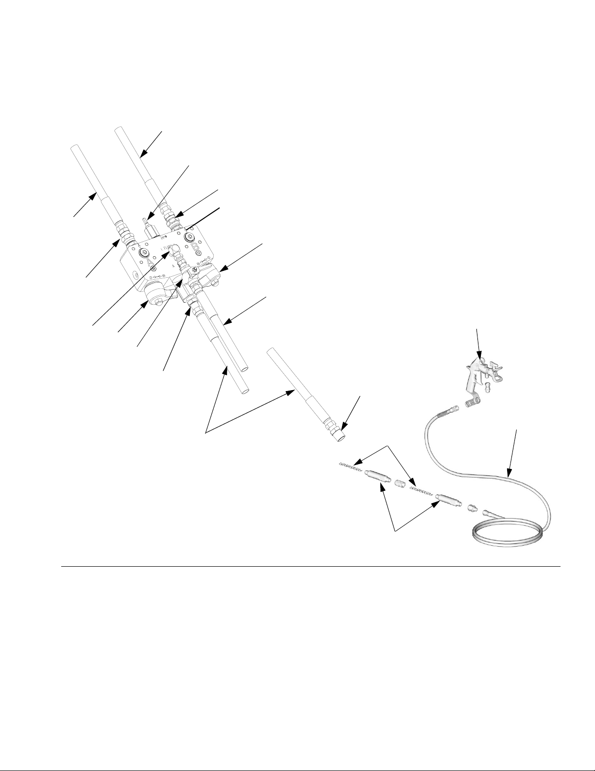
Component Identification
M
E
F
P, R
L
FIG. 1: Typical Installation
Key:
A Resin (High Volume) Supply Hose (A material)
B Hardener (Low Volume) Supply Hose (B material)
C Resin Adapter Nipple
D Hardener Adapter Nipple
E Resin Shutoff Handle (blue; A material)
F Solvent Inlet Valve, 1/4 npt(m)
G Grounded Solvent Hose
H Hardener Shutoff Handle (green; B material)
J Hardener Restrictor Adjustment
K Hardener Screen (inside)
L Integrator Hose
U
V
T
W
S
M Solvent Check Valve
P Hardener Injector (not shown; inside outlet R)
R Mix Manifold Outlet, 1/2 npt(f) with 3/8 npt(m) adapter
S Static Mixer Housing
T Fluid Whip Hose
U Airless Spray Gun
V Static Mixer Adapter
W Static Mixing Element
312749G 7
Page 8
Overview
Overview
XM plural-component sprayers can mix most two component epoxy and urethane protective coatings. When
using quick-setting materials (less than 10 minute pot
life) a remote mix manifold must be used.
The left side of the mix manifold is intended for the
major volume material, or the higher viscosity material if
using a 1:1 volume mix. This side is referred to throughout the manual as the resin side or “A” side.
The right side is referred to as the Hardener side or “B”
side. The “B” side incorporates a 40 mesh strainer and
an adjustable restrictor for balancing the system back
pressure and flow.
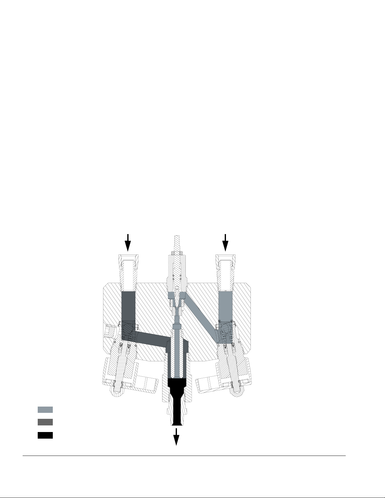
See F
IG
. 2 to view flow of A and B material inside the
XM Mix Manifold.
Resin Hardener
The resin and hardener enter the manifold through the
manifold inlet ports. The “A” material flows through the
manifold to the material outlet port. The injector tube
creates a hollow stream of “A” material for the “B” material to fill once the hardener exits the injector tube. The
mixed resin and hardener material enters the mix manifold outlet (R) before the mixed material enters the integrator fluid hose. Adjust the restrictor housing to
balance the system back pressure and flow.
NOTE: Always use the integration hose, supplied with
your XM plural-component sprayer, after the mix manifold.
NOTE: Please follow these recommendations for setup:
• Use at least a 3/8 in. (10 mm) x 25 ft. (7 m) integrator hose.
• Install at least 24-elements of static mixer after the
integration hose and before the spray gun whip
hose.
AB
Hardener
Resin
Mixed Material
F
IG
. 2: Cutaway View
8 312749G
r_255684_256980_312749_17a
Page 9
Installation
This manifold is designed for use on proportioning
pumps with independent drive motors. Use of this
manifold on a mechanically linked sprayer without
using mechanically linked on/off A and B valves may
cause hazardous fluid pressures that can rupture
equipment.
Installation
Machine Mounted Restrictor Valve
When the mix manifold is used remotely a restrictor
valve (222200) is added to the B side outlet of the proportioner. This configuration requires that the machine
outlet restrictor be used to set the bar graph on the Ratio
Mode screen.
Remote Circulation Control
For assistance in setting up a plural component sprayer,
contact your Graco distributor, to ensure that you select
the proper type and size equipment for your system.
Fluid Inlets
The A and B fluid inlets are equipped with 1/2 npsm
unions in 1/2 in. npt(f) ports. Connect 1/2 in., 3/8 in, or
1/4 in. npsm(f) fluid hoses using the two adapter nipples
(provided).
Remote Mounted Manifolds
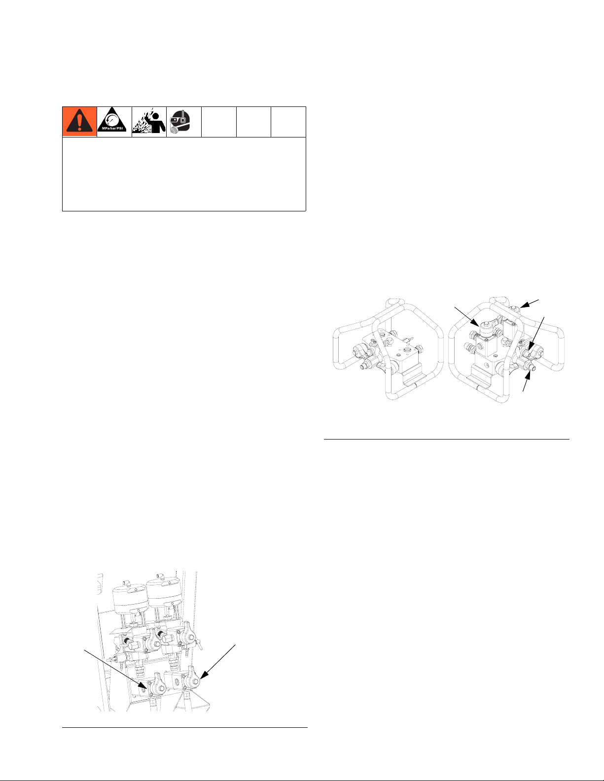
Machine Outlet Check Valves
The XM sprayer must have outlet check valves (CV) in
order to accurately measure pump outlet flow. These
check valves are provided in the mix manifold when it is
mounted on the sprayer.
When the mix manifold is removed and used remotely,
you must add outlet check valves on the machine. Use
shutoff check valves 255278 as the outlet check valves
as provided in conversion kit 256980. The valves act as
severe duty check valves when the check valve handle
is open. They act as manual shutoff valves when the
handle is closed.
Valves
Shutoff check valves (CV) may also be face-mounted on
the remote mix manifold to circulate heated material
before spraying.
CV
r_255684_256980_312749_4
F
IG
. 4: Remote Mix Manifold Options on Carriage
CV
F
R
CV
F
IG
. 3: Machine Outlet Check Valves
312749G 9
CV
Page 10

Grounding
Solvent Inlet
Connect the solvent supply line (G) from the solvent
pump to the 1/4 npt(m) solvent inlet valve (F). Use a
Graco approved grounded hose rated to withstand the
maximum fluid working pressure of the solvent pump.
The hose core must be chemically compatible with the
solvent being used such as nylon or PTFE.
Fluid Outlet
Connect a 3/8 in. ID x 25 ft. (minimum) integrator hose
(L) to the fluid outlet (R). Then connect the static mixers
(S) and whip hose (T) to the 3/8 npt(f) integrator hose
(L). Two static mixers are often used, in series.
Mounting
To mount the bare manifold, drill four holes in the
mounting surface, and secure with four 5/16-18 x 1/2 in.
(50 mm) screws. See the following illustration for details
and dimensions.
6.38 in. (162.05 mm)
• Mix manifold and solvent flush system: use only
a Graco approved grounded solvent hose. Not all
heated hoses are grounded, and the mix manifold
primary ground is through the solvent hose. Ensure
that the solvent pump is properly grounded, as
instructed in your solvent pump manual. Ensure
there is electrical continuity from the spray tip to the
grounded solvent hose.
• Air compressor: Follow manufacturer’s recommendations.
• Spray gun/dispense valve: ground through connection to a properly grounded fluid hose and pump.
• Fluid supply container: follow local code.
• Object being sprayed: follow local code.
• Solvent pails used when flushing: follow local
code. Use only conductive metal pails, placed on a
grounded surface. Do not place the pail on a nonconductive surface, such as paper or cardboard,
which interrupts grounding continuity.
• To maintain grounding continuity when flushing
or relieving pressure: hold metal part of the spray
gun/dispense valve firmly to the side of a grounded
metal pail, then trigger the gun/valve.
1.44 in.
(36.57 mm)
11/32 diameter
Grounding
Your system must be grounded. Read warnings in
your sprayer manual. Check your local electrical code.
• Pump: use a ground wire and clamp as instructed
in your sprayer operation manual.
• Air and fluid hoses: use only electrically conductive hoses with a maximum of 500 ft (150 m) combined hose length to ensure grounding continuity.
Check electrical resistance of hoses. If total resistance to ground exceeds 29 megohms, replace
hose immediately.
Flush Before Using Equipment
The equipment was tested with lightweight oil, which is
left in the fluid passages to protect parts. To avoid contaminating your fluid with oil, flush the equipment with a
compatible solvent before using the equipment. See
Flush, page 12.
10 312749G
Page 11

Operation
Operation
Pressure Relief Procedure
Follow pressure relief procedure when you stop spraying or dispensing; and before cleaning, checking, servicing, or transporting equipment.
Relieve A and B Fluid Pressure
1. Engage trigger lock.
ti1949a
2. Press Stop to turn off sprayer.
3. Close all air motor supply valves or any source of
fluid pressure.
7. Disengage trigger lock.
1.440 in.
(36.58 mm)
8 X 5/16-18 UNC 2B
ti1950a
8. Hold a metal part of the gun firmly to a grounded
metal pail with a splash guard in place. Trigger gun
to relieve pressure in material hoses.
ti1953a
9. Engage trigger lock.
4. Open A and B circulation valves if equipped. See
F
IG
. 3 and FIG. 4 on page 9.
5. If fluid heaters are used, shut them off using the
controls on the heater control box.
6. Shut off feed pumps, if used.
ti1949a
10. Flush mixed material hoses, mixer, and gun. See
Flush on page 12.
312749G 11
Page 12

Operation
Flush
3. Close blue (E) A material and green (H) B material
supply valves.
Read warnings and grounding instructions in your
sprayer manual. If your system uses heaters, shut off
the main power to the heaters and heated hose control before flushing.
NOTICE
To prevent fluid from setting up in the dispensing
equipment, flush the system frequently. Be sure
there is an adequate amount of solvent in the solvent
supply before spraying.
NOTE:
• Ensure flushing fluid is compatible with dispense
fluid and the equipment wetted parts.
• Solvent may channel through viscous fluids and
leave a coating of mixed fluid on the inner tube of
your hose. Be sure all fluid is thoroughly flushed from
the hose after each use.
• Remove spray tip for more thorough cleaning of the
whip hose and static mixers.
NOTE:
The valve handles point at each other in the closed position.
E
H
4. Open solvent inlet valve (F).
F
5. Turn on solvent flush pump.
• Use a solvent that dissolves the material you are
mixing.
• Always leave equipment filled with fluid to avoid drying and scaling.
1. Relieve pressure; see page 11.
2. Engage trigger lock. Remove spray tip.
4)!
ti1949a
ti1948a
6. Disengage spray gun trigger lock.
ti1950a
7. Trigger gun into a grounded metal pail with lid. Use
a lid with a hole to dispense through to avoid splashing. Be careful to keep fingers away from front of
gun. Flush out mixed material until clean solvent
dispenses.
ti1953a
8. Turn off solvent pump air supply.
12 312749G
Page 13

Operation
9. Hold the metal part of the gun firmly to a grounded
metal pail with lid in place. Trigger gun until all fluid
pressure is relieved.
ti1953a
10. Engage trigger lock.
ti1949a
11. Close solvent inlet valve (F).
Dispensing and Spraying
1. Close solvent inlet valve (F).
F
2. Open blue (E) A material and green (H) B material
valves.
HE
F
3. Ensure sprayer is in “Spray Mode” and push start.
4. Disengage spray gun trigger lock.
ti1950a
5. Hold the metal part of the gun firmly to a grounded
metal pail with a lid to avoid splashing. Trigger the
gun until mixed coating material is evident and
purge solvent is gone.
6. Proceed spraying.
312749G 13
Page 14

Operation
Volume Balancing the Mix Manifold
When the mix manifold is remote mounted ratio errors
can occur between the sprayer and the mix manifold;
even when the sprayer output ratio is accurate.
The following can occur when the hoses are not volume
balanced to the mix ratio:
• Hoses fill to high pressure while metering on ratio.
• Only the “A” material hose comes up to spray pressure.
• Off ratio at the mix point until hose pressures equalize.
Lead/Lag Imbalance
When resin and hardener volume requirements (ratio)
and/or viscosities are different an imbalance can occur
each time the gun is triggered. This occurs because the
fluids can rush out of the manifold near a 1:1 ratio before
the sprayer starts.
Remote Mounted Mix Manifold
Set Machine Restriction
With the restriction stem on the remote mix manifold
open counter clockwise, adjust the restriction stem
(222200) on the outlet of the proportioner to optimize
the B side dosing control window. The goal is to create
constant flow on the A side and frequent dosing or near
constant flow on the B side. See the XM operation manual for instructions.
Set Mix Manifold Restriction
1. Adjust the restriction stem clockwise until the bar
graph on the Ratio Mode screen starts moving to
the left. The “B” dosing valve (blue) light will get
brighter and the “B” dosing valve will open further.
2. Turn the restriction valve counter clockwise a half
turn, and then lock the adjustment by tightening the
nut.
Adjust Restriction on Early Xtreme Mix
Sprayers
To avoid this imbalance:
• Add restriction on the hardener (low volume) side to
balance the flow at the mix manifold.
• If the mix manifold is remote, pressurize hoses to
spray pressure before starting spray mode when
mix manifold is remote.
• If the mix manifold is remote, size the fluid delivery
hose volume to nearly match the mix ratio. See
Table 1.
Adjust B Mix Manifold Restriction on XM
Sprayers While Spraying
Machine Mounted Mix Manifold
Adjust the restriction stem on the mix manifold to optimize the B side dosing control window. The goal is to
create a constant flow on the A side and frequent dosing
or a near constant flow on the B side. See the XM operation manual for instructions.
To check if the system is balanced watch the “B” dosing
valves. The valve should be open (up) most of the time
when the gun is triggered. If the “B” valve is giving only
short “on” shots, adjust the restrictor in further. “B” fluid
should flow most of the time, making only short “off” corrections.
Hose Selection For Feeding A Remote Mix
Manifold
Hoses should be sized to match the hose volume ratio
to the mix ratio. The hose size should also allow for minimum pressure drop on the major volume side to meet
your flow requirements.
Use Table 1 to match mix ratio, hose selection, and volume ratio. Use Table 2 on page 15 to reference amount
of pressure drop for 50 ft lengths of different hose sizes.
Size remote mix manifold hoses to:
• Minimize pressure drop on the high volume and
often higher viscosity resin side to achieve higher
flow and pressure at the gun while spraying.
• Allow both A and B material hoses to come up to
spray pressure together when A and B fluids are
metered into the hoses on ratio.
14 312749G
Page 15

Operation
• Balance the inherent stall pressure between the
resin “A” and hardener “B” sides when the gun
closes and also when triggered. This reduces the
lead/lag error at the mix point when the spray gun is
triggered.
Table 1: Volume Ratio of “A” to “B” Hose
Hose
Mix Ratio
Selection
“A” x “B”
Hose Volume
Ratio
1:1 1/2 x 1/2 1.0:1
3/8 x 3/8
2:1 1/2 x 3/8 1.78:1
3/8 x 1/4 2.25:1
3:1 3/8 x 1/4 2.25:1
4:1 to 6:1 1/2 x 1/4 4.0:1
6:1 to 10:1 1/2 x 3/16 7:1
Table 2: Hose Selection by Pressure Drop
Example: At a 4:1 mix ratio, a 1/2 in. ID resin hose and
a 1/4 in. ID hardener hose matches the 4:1 volume ratio.
Pressure Drop per 15.24
meter section per 1000
cps at 1 liter/min.
Hose ID
(in.)
Pressure drop per 50 ft
section per 1000 cps at 1
gal/min.
(psi)
1/8 55910 1018
3/16 11044 201
1/4 3494 64
3/8 690 13
1/2 218 4
5/8 89 1.62
3/4 43 0.78
#1 Example: What is the pressure loss of a 2000 cps
material through 150 ft of 3/8 in. ID hose at 0.75 gpm?
690 psi (from chart) x 2 (viscosity factor 2 x 1000 cps) x
3 (3 x 50 ft hoses) x 0.75 (% of gpm) = 3105 psi loss
That is a lot of pressure loss before the spray gun. Let’s
try 1/2 in. hose. See example #2.
Reference Formula
Pressure drop = 0.0273 QVL/D
(Bar)
Key:
Q = Vis poise.
V= Gallons per minute
L= Length (ft)
D=Inside diameter (in.)
#2 Example: What is the pressure loss of a 2000 cps
material through 150 ft of 1/2 in. ID hose at 0.75 gpm?
218 psi (from chart) x 2 (viscosity factor 2 x 1000 cps) x
3 (3 x 50 ft hoses) x 0.75 (% of gpm) = 981 psi loss
4
312749G 15
Page 16

Operation
Optional Recirculation
Ports are provided on the “A” and “B” sides for recirculating the material hoses back to the machine supplies.
To add remote recirculation, install shutoff check valves
255278 on front of mix manifold assembly. This is a high
quality carbide ball and seat valve designed to close and
be leak free when in spray mode.
Use adjustable restrictor valves 222200 to control the
flow rate back into the supply.
r_255684_256980_312749_4
F
IG
. 5: Remote Mix Manifold Recirculation
NOTE:
When recirculation valves are moved remote downstream of the dosing valves, the machine can no longer
automatically check that the recirculation valves are
closed and leak free when going into Spray Mode.
If the recirculation valves leak while you are spraying,
you will be off ratio with no indication. See XM sprayer
operation manual 312359 for more information.
16 312749G
Page 17

Troubleshooting
Troubleshooting
1. Relieve the pressure before you check or service
any system equipment.
2. Check all possible causes and solutions in the troubleshooting chart before disassembling the manifold.
Problem Cause Solution
Little or no resin output. Fluid inlet is plugged. Clean inlet; remove obstruction. See
Clean Mix Manifold Outlet, page 20.
Fluid container is empty. Refill.
Little or no hardener output. Fluid inlet is plugged. Clean inlet; remove obstruction. See
Clean Mix Manifold Outlet, page 20.
Fluid container is empty. Refill.
Hardener screen (28) is plugged. (Only
applies if it is installed.)
Mixed fluid will not flush out. Fluid is hardened in static mixers or whip
hose.
Solvent supply container is empty. Refill.
Solvent is not compatible with fluid. Change to compatible solvent.
Hardener pressure higher than normal. Hardener is cold. Correct heat problem. See fluid heater
Restrictor or screen plugging up. Open restrictor or clean screen. See
Hardener pressure lower than normal. Resin is cold. Flow rate is low. Correct heat problem. See fluid heater
Worn hardener restrictor. Adjust restrictor. See Adjust B Mix Mani-
Spray pattern developing tails. Static mixer and/or whip hose plugging
up.
Low pressure from sprayer. Check air supply pressure. Check inlet air
Cold material. Increase heat. See XM Plural-Compo-
Too much pressure drop. Use larger hoses or more heat.
Resin or hardener does not shut off. Damaged ball or seat or seal in valve
(11).
Off ratio condition after increasing spray
pressure in spray mode with a remote mix
manifold.
Hoses not volume balanced. Volume balance A and B remote material
Clean hardener screen. See Clean Mix
Manifold Outlet, page 20.
Clean with compatible solvent. See Main-
tenance, page 20. Replace as necessary.
section of XM Plural-Component Sprayer
Repair manual 313289.
Clean Mix Manifold Outlet, page 20.
section of XM Plural-Component Sprayer
Repair manual 313289.
fold Restriction on XM Sprayers While
Spraying, page 14.
Replace restrictor.
Clean Static Mixers, page 20.
Clean spray gun and tip. See gun manual.
gauges while spraying.
nent Sprayer Operation manual 312359.
Replace or rebuild valve (11). See repair
section of High Flow Severe Duty Shutoff
Check Valve manual 313343.
hoses closer to volume mix ratio. See
Volume Balancing the Mix Manifold,
page 14.
312749G 17
Page 18

Repair
Repair
Follow Pressure Relief Procedure when you stop
spraying and before cleaning, checking, servicing, or
transporting equipment. Read warnings in your
sprayer manual.
Remove Restrictor
1. Note number of turns from open to closed position.
Remove restrictor housing (19) from manifold (1).
2. Place restrictor housing (19) in a vice and remove
nut (20).
20
NOTICE
• Be sure to label all fluid parts “resin” or “hardener” when disassembling them. Doing so prevents interchanging resin and hardener parts
during reassembly, which will contaminate the
materials and the fluid path through the equipment.
• Color-coded chemically resistant tape may be
used to label the parts. Use blue for resin and
green for hardener.
1. Relieve the pressure, see page 11.
2. Clean “B” side screen. See page 20.
3. Remove cap nut (CN) and handle (CH) from cartridge assembly (11). Use wrench to remove cartridge assemblies from manifold (1). See manual
313343 for repair instructions.
1
19
1
r_255684_256980_312749_9a
FIG. 7
3. Unscrew stem (18) clockwise and remove from
restrictor housing (19).
19
18
16
17
IG
. 8
F
r_255684_256980_312749_10a
4. Remove and inspect o-rings (16, 17). Replace as
11
necessary.
5. Remove set screw (15) and seat (14) from manifold
CH
CN
r_255684_256980_312749_18a
F
IG
. 6
(1).
14
15
4. Clean all parts thoroughly in a compatible solvent.
Use a soft bristle brush to clean the manifold passageways.
F
IG
. 9
18 312749G
r_255684_256980_312749_11a
Page 19

Assemble Restrictor
Repair
1. Insert seat (14) with larger tapered end facing up in
manifold (1).
20
19
18
1
16 (black)
17 (white)
15
14
r_255684_256980_312749_12a
IG
. 10
F
4. Loosely install lock nut (20) on stem (18).
5. Tighten restrictor housing (19) into manifold (1).
6. Tighten stem (18) down until it bottoms on seat (14).
Then back stem out to previously noted position or
two full turns and lock in place with lock nut (20).
Assemble Cartridge Assembly
1. Apply blue thread lock to external threads of cartridges (11) and install in manifold with stem backed
out fully counter-clockwise. Place wrench on cartridge flats and torque to 125 ft-lbs (170 N•m). See
F
IG
. 6 on page 18.
2. Install handle (CH) and cap nut (CN) on cartridge so
that the handles point toward each other when
closed.
2. Apply blue thread lock to external threads of set
screw (15) and install in manifold.
3. Install o-rings (16, 17) on stem (18) and insert stem
into restrictor housing (19). Turn stem (18) counter-clockwise until in open position.
20
19
18
16 (black)
17 (white)
r_255684_256980_312749_13a
CN
F
IG
. 12
CH
F
IG
. 11
312749G 19
Page 20

Maintenance
Maintenance
Clean Static Mixers
See FIG. 1, page 7. Typically, two static mixer housings
(S, Part No. 262478) are connected to the static mixer
adapter (V) on the integrator hose (L). These housings
use plastic mix elements, available in a package of 25
(W, Part No. 248927).
NOTICE
Never use a swivel union on the mixer inlets. The
union will compress the tube and make it impossible
to remove the mix element.
To clean the housing and replace the mix element:
1. Relieve pressure, see page 11. Remove mixer
housings (S) from integrator hose (L) and from whip
hose (T).
2. Place flats of mixer housing (S) in a grounded vise.
Push mix element (W) out of the inlet end.
3. If necessary, use a 1/2 in. drill bit to drill out old
material and clean the mix element from the inlet
end, down to the internal shoulder at the outlet end.
2. Pull “V” screen (28) and retainer o-ring (29) straight
up and out with a needle nose pliers.
3. Clean or replace screen (28).
4. Reinstall screen (28) and white plastic o-ring (29)
with tool 15T630 (included in repair kit 256238).
NOTE:
The o-ring (29) is used as a retainer ring, not a seal. It
may be scratched or deformed from pushing the screen
(28) back in.
5. Install “B” inlet union (31) on manifold block (1).
Clean Mix Manifold Outlet
1. Remove outlet fitting (33) to expose “B” center injection tube (9).
4. Use a brush to clean any debris in housing (S).
5. Insert new mix element, wide end first.
Clean “B” Side Screen
NOTE:
The following instructions apply only when using the
strainer accessory for low viscosity fluids. See Acces-
sories on page 26.
1. Remove “B” inlet union (31) from manifold block (1).
31
1
29
28
9
33
2. Clean any build-up on, around, or inside the tube
(9).
3. Reinstall outlet fitting (33).
20 312749G
Page 21

Parts
255684 Mix Manifold
Parts
20
19
2
Detail A
11j
11a
1
FLOW DIRECTION
31
2
11b
11c
11d
18
1
29◆
28◆
5
5
1
5
6
11e
11g
1
16
17
11f
11h
1
4
1
15
3
14
8
2
3
2
22
34
21
2
3
2
11, see Detail A
24
7
13
4
2
2
34
2
21
2
23
7
9
10
2
33
2
FLOW DIRECTION
r_255684_256980_312749_15a-1
13
2
SOLVENT DIRECTION
35
5
1
Apply lithium grease.
2
Apple anaerobic pipe thread sealant.
3
Apply blue thread lock to external
threads.
4
Torque to 125 ft-lbs. (170 N•m).
5
Plastic assembly tool for (28), (29), and
(11d) included in repair kit 256238.
6
U-cup open lips face spring.
7
After tightening valves (11) into housing
(1), orient handles (23, 24) to face each
other when closed.
8
Large end of inside taper faces out.
◆
Accessory only.
r_255684_256980_312749_6
312749G 21
Page 22

Parts
255684 Mix Manifold
Qty
Ref. Part Description
1 15M229 BLOCK, manifold 1
2† 117558 SPRING, compression 1
3† 101947 BALL, solvent check 1
4 15E367 ELBOW, street, lapped 1
5 214037 VALVE, ball; see manual 306861 1
9 15R378 TUBE, injector, hardener 1
10 15R067 PIPE, outlet, mixer manifold 1
11* 255747 CARTRIDGE, valve, shutoff
check; includes 11a-11j
11a† 15A968 SEAT, foot valve, carbide 1
11b† 116166 BALL, carbide 1
11c† 15M530 SPRING 1
11d† 15M529 SEAL, u-cup UHMWPE 1
11e† 15M189 SPACER, backup, seal 1
11f† 15K347 STEM 1
11g† 121138 PACKING, o-ring; PTFE, white 1
11h 15K199 HOUSING, top, check valve 1
11j† 15K692 SEAL, seat retainer 1
13 117623 NUT, cap; 3/8-16 2
14 183951 SEAT, valve, carbide 1
15 15R382 SCREW, set, hollow, 3/4-16 1
16† 113137 PACKING, o-ring, black solvent
resist
17† 110004 PACKING, o-ring, white, PTFE 1
18 235205 STEM, valve, carbide 1
19 15M969 HOUSING, restrictor 1
20 110005 NUT, jam, hex; 5/16-24 unf 1
21 100721 PLUG, pipe; 1/4 npt(f) 2
22 101754 PLUG, pipe; 3/8 npt(f) 1
23 15R380 HANDLE, green 1
24 247789 HANDLE, blue 1
31 156684 UNION, adapter; 1/2 npt 2
32✿ 158491 NIPPLE; 1/2 npt, see page 23 2
33✿ 159239 NIPPLE, pipe; 1/2 x 3/8 npt, see
page 23
34 100361 PLUG, pipe; 1/2 in. - 14 npt 2
35 156823 UNION, swivel; 2 x 1/4-18 npt 1
45✿ 162449 NIPPLE, 1/2 x 1/4 npt, see page 232
.
2
1
3
118✿ 126786 WRENCH, restrictor 1
†
Provided in mix manifold repair kit 256238.
* See manual 313343 for repair instructions.
✿
Not shown.
22 312749G
Page 23

Parts
256980 Remote Mix Manifold Conversion Kit
(with outlet check/shut off valves and machine mounted restrictor valve)
Shutoff check valves must be used when using the mix manifold remote on an XM sprayer. Includes everything
needed to move the existing mix manifold remote, except the A and B fluid hoses which should be chosen according
to the guidelines starting on page 14.
NOTE: Extra hose nipples are included to accommodate 1/2 in. or 3/8 in. “A” hose and 1/2 in., 3/8 in., or 1/4
in. “B” hose.
31
102
108
103
111
23
13
109
101
110
110
45
33
33
32
32
1
1
112
112
r_255684_256980_312749_8
r_255684_256980_312749_8
2
2
32
119
32
113
24
115
1
1
Mix manifold 255684 is not included (purchase
Mix manifold 255684 is not included (purchase
separately). See page 21 for parts.
separately). See page 21 for parts.
2
2
Face down.
Face down.
3
3
“B” outlet to hose.
“B” outlet to hose.
33 or 116
WLE
32
33
312749G 23
114
or 117
Page 24

Parts
256980 Remote Mix Manifold Kit Parts
Qty
Ref. Part No. Description
13 117623 NUT, cap 3/8-16 unc 2
23 15R380 HANDLE, green 1
24 15J916 HANDLE, blue 1
31 156684 UNION, adapter 2
32★ 158491 NIPPLE, 1/2 npt 3
33★ 159239 NIPPLE, pipe; 1/2 x 3/8 npt 5
45★ 162449 NIPPLE; 1/2 x 1/4 npt 2
101 262522 CARRIAGE, remote manifold 1
102 15R529 BLOCK, fluid distribution 2
103* 255278 VALVE shutoff/check;
(includes 11, see page 22)
108† 121139 PACKING, o-ring 2
109 121295 SCREW, cap, sch 8
110 111801 SCREW, cap, hex hd; 5/16-18 4
111 100361 PLUG, pipe 2
112 551387 GAUGE, pressure, fluid 1
113 162505 UNION; 3/8 male x 1/2 female 1
114 222200 VALVE, restrictor 1
115 155699 ELBOW, street; 3/8-18 npt 1
116 156849 NIPPLE, pipe; 2 x 3/8-18 npt 1
117 164672 ADAPTER; 3/8-18 npt x 1/4-18
npsm
118✿ 126786 WRENCH, restrictor 1
119 16N367 COUPLING, 1/2 x 3.5 in. 1
32
.
113
115
114
33 or 116 or 117
2
1
★
Use to adapt to any combination of one 1/2 in., two
3/8 in., and one 1/4 in. hoses.
†
Provided in mix manifold repair kit 256238.
* See manual 313343 for repair instructions.
✿
Not shown.
24F284 Remote Manifold Restrictor Kit
Qty
Ref. Part No. Description
32★ 158491 NIPPLE, 1/2 npt 1
33★ 159239 NIPPLE, pipe; 1/2 x 3/8 npt 1
113 162505 UNION; 3/8 male x 1/2 female 1
114 222200 VALVE, restrictor 1
115 155699 ELBOW, street; 3/8-18 npt 1
116 156849 NIPPLE, pipe; 2 x 3/8-18 npt 1
118✿ 126786 WRENCH, restrictor 1
.
24 312749G
Page 25

Repair Kit
256238, XM Mix Manifold without
Circulation Repair Kit
See parts lists on pages 22 and 23.
Qty
Ref. Part Description
2 117558 SPRING, compression 1
3 101947 BALL, solvent check 1
11a 15A968 SEAT, foot valve, carbide 1
11b 116166 BALL, carbide 1
11c 15M530 SPRING 1
11d 15M529 SEAL, u-cup UHMWPE 1
11e 15M189 SPACER, backup, seal 1
11f 15K347 STEM 1
11g 121138 PACKING, o-ring; PTFE, white 1
11j 15K692 SEAL, seat retainer 1
16 113137 PACKING, o-ring, black solvent
resist
17 110004 PACKING, o-ring, white, PTFE 1
108 121139 PACKING, o-ring 2
120✿ 15T630 TOOL, u-cup and manifold 1
121✿ 113500 ADHESIVE, anaerobic 1
Repair Kit
.
1
✿
Not shown.
312749G 25
Page 26

Accessories
Accessories
255747, Shutoff Check Valve Cartridge
Assembly
See manual 313343 for parts.
255278, Complete High Flow Sever Duty
Shutoff Check Valve
Includes housing, screws, and o-ring for recirculation or
machine with outlet valves. See manual 313343 for
parts.
10,000 psi Fluid Pressure Gauge (2.5 in.)
114434 - 1/4 npt(m) back mount pressure gauge can be
used in port (AB) as gun pressure gauge. Includes 316
stainless steel wetted.
551387 - 1/4 npt bottom mount version.
262522, Remote Mix Manifold Carriage
(101)
The carriage holds and protects the mix manifold
assembly. This requires four 5/16-18 x 1/2 in. screws.
262478, 7250 psi Static Mixer Housing
Accessory Ports
See FIG. 13.
(AA) Inlet Side - 1/2 in. npt(f)
These ports are located before “A” and “B” shutoff check
valves. Use these ports for inlet gauges or recirculation.
They also are equipped to manifold face mount 255278
circulation valves.
(AB) “A” Side After Shutoff - 1/4 in. npt(f)
These ports are located after “A” and “B” shutoff check
valves. Use these ports as an outlet pressure gauge or
as a second flush inlet for materials that require dual,
separate flushing for complete flush material isolation.
(AC) “B” Side After Shutoff, Before Restrictor - 1/4
in. npt(f)
This port can be used as an alternate flush coming in
before the restrictor on the “B” side.
AA
AB
AA
3/8 npt(m) holds 1/2 in. 12 element stick from 25 pack
248927.
248927, Plastic Mix Elements
25 pack of 1/2 in. x 12 elements plastic sticks.
511352, Mixer
Stainless 3/8 npt(m) pipe with 12 element stainless
welded stick; 7250 psi (50 MPa, 500 bar).
15B729, Adapter Mixer Inlet
3/8 npt m x f; 7250 psi (50 MPa, 500 bar).
162024, Adapter Between Mix Tubes
3/8 npt f x f; 7250 psi (50 MPa, 500 bar).
B-side Screen
For low viscosity fluids only.
185416 STAINER; 40m
121410 PACKING, screen retainer
AB
F
IG
. 13: Accessory Ports
AC
26 312749G
Page 27

Technical Data
Technical Data
Maximum working pressure 7250 psi (50 MPa, 500 bar)
Maximum fluid temperature 160° F (71° C)
Fluid inlet 1/2 in. npsm union with nipple adapters for 1/2 in., 3/8 in., or 1/4 in. hoses
Fluid outlet size 1/2 npt(f) with 3/8 npt(m) adapter nipple
Solvent inlet valve 1/4 npt(m)
Wetted parts
Manifold block and internal parts:
bide, electroless nickel plated steel, zinc plated steel, UHMWPE
Flush valves and fittings:
steel, acetal, PTFE
440 stainless steel, plated carbon steel, hardened alloy
302 and 303 stainless steel, PTFE, tungsten car-
312749G 27
Page 28

Graco Standard Warranty
Graco warrants all equipment referenced in this document which is manufactured by Graco and bearing its name to be free from defects in
material and workmanship on the date of sale to the original purchaser for use. With the exception of any special, extended, or limited warranty
published by Graco, Graco will, for a period of twelve months from the date of sale, repair or replace any part of the equipment determined by
Graco to be defective. This warranty applies only when the equipment is installed, operated and maintained in accordance with Graco’s written
recommendations.
This warranty does not cover, and Graco shall not be liable for general wear and tear, or any malfunction, damage or wear caused by faulty
installation, misapplication, abrasion, corrosion, inadequate or improper maintenance, negligence, accident, tampering, or substitution of
non-Graco component parts. Nor shall Graco be liable for malfunction, damage or wear caused by the incompatibility of Graco equipment with
structures, accessories, equipment or materials not supplied by Graco, or the improper design, manufacture, installation, operation or
maintenance of structures, accessories, equipment or materials not supplied by Graco.
This warranty is conditioned upon the prepaid return of the equipment claimed to be defective to an authorized Graco distributor for verification of
the claimed defect. If the claimed defect is verified, Graco will repair or replace free of charge any defective parts. The equipment will be returned
to the original purchaser transportation prepaid. If inspection of the equipment does not disclose any defect in material or workmanship, repairs
will be made at a reasonable charge, which charges may include the costs of parts, labor, and transportation.
THIS WARRANTY IS EXCLUSIVE, AND IS IN LIEU OF ANY OTHER WARRANTIES, EXPRESS OR IMPLIED, INCLUDING BUT NOT
LIMITED TO WARRANTY OF MERCHANTABILITY OR WARRANTY OF FITNESS FOR A PARTICULAR PURPOSE.
Graco’s sole obligation and buyer’s sole remedy for any breach of warranty shall be as set forth above. The buyer agrees that no other remedy
(including, but not limited to, incidental or consequential damages for lost profits, lost sales, injury to person or property, or any other incidental or
consequential loss) shall be available. Any action for breach of warranty must be brought within two (2) years of the date of sale.
GRACO MAKES NO WARRANTY, AND DISCLAIMS ALL IMPLIED WARRANTIES OF MERCHANTABILITY AND FITNESS FOR A
PARTICULAR PURPOSE, IN CONNECTION WITH ACCESSORIES, EQUIPMENT, MATERIALS OR COMPONENTS SOLD BUT NOT
MANUFACTURED BY GRACO. These items sold, but not manufactured by Graco (such as electric motors, switches, hose, etc.), are subject to
the warranty, if any, of their manufacturer. Graco will provide purchaser with reasonable assistance in making any claim for breach of these
warranties.
In no event will Graco be liable for indirect, incidental, special or consequential damages resulting from Graco supplying equipment hereunder, or
the furnishing, performance, or use of any products or other goods sold hereto, whether due to a breach of contract, breach of warranty, the
negligence of Graco, or otherwise.
FOR GRACO CANADA CUSTOMERS
The Parties acknowledge that they have required that the present document, as well as all documents, notices and legal proceedings entered into,
given or instituted pursuant hereto or relating directly or indirectly hereto, be drawn up in English. Les parties reconnaissent avoir convenu que la
rédaction du présente document sera en Anglais, ainsi que tous documents, avis et procédures judiciaires exécutés, donnés ou intentés, à la suite
de ou en rapport, directement ou indirectement, avec les procédures concernées.
Graco Information
For the latest information about Graco products, visit www.graco.com.
For patent information, see www.graco.com/patents.
TO PLACE AN ORDER,
Phone: 612-623-6921 or Toll Free: 1-800-328-0211 Fax: 612-378-3505
All written and visual data contained in this document reflects the latest product information available at the time of publication.
GRACO INC. AND SUBSIDIARIES • P.O. BOX 1441 • MINNEAPOLIS MN 55440-1441 • USA
Copyright 2009, Graco Inc. All Graco manufacturing locations are registered to ISO 9001.
contact your Graco distributor or call to identify the nearest distributor.
Graco reserves the right to make changes at any time without notice.
Original instructions. This manual contains English. MM 312749
Graco Headquarters: Minneapolis
International Offices: Belgium, China, Japan, Korea
www.graco.com
Revised April 2014
 Loading...