

Page 1
Instructions
Dyna-Star® HP, HF, 10:1
Pumps: 120# and 400#
Drum Cover and Follower
312738C
Plate
Drum Cover and Follower Plate for use with Dyna-Star 10:1, HP, or HF Pumps. For
professional use only.
Important Safety Instructions
Read all warnings and instructions in this
manual and in the Dyna-Star Pump HP, HF or
10:1 instruction manual. Save all instructions.
To reduce the risk of serious bodily injury, including
splashing fluid in the eyes or on the skin and injury
from moving parts, ALWAYS follow the pressure
relief procedure in the separate pump manual
before you install any of these components when you
change the drum.
EN
Drum Cover Models
Model Number
247443 120 lb. 247443 NA NA
247704 400 lb. 247450 NA NA
77X514 120 lb. NA 77X002 77X015
77X515 400 lb. NA 77X003 77X016
Follower Plate Models
Model Number
247701 120 lb. 247443 NA 77X015, 77X121
247702 400 lb. 247450 NA 77X016, 77X122
77X511 120 lb. NA 77X002, 77X111 NA
77X512 400 lb. NA 77X003, 77X112 NA
Compatible Refinery
Drum Size
Compatible Refinery
Drum Size
Compatible Dyna-Star Pump
10:1 HP HF
Compatible Dyna-Star Pump
10:1 HP HF
Page 2
Follower Plate Installation
Pack Cone with Grease
Pack Cone with Grease
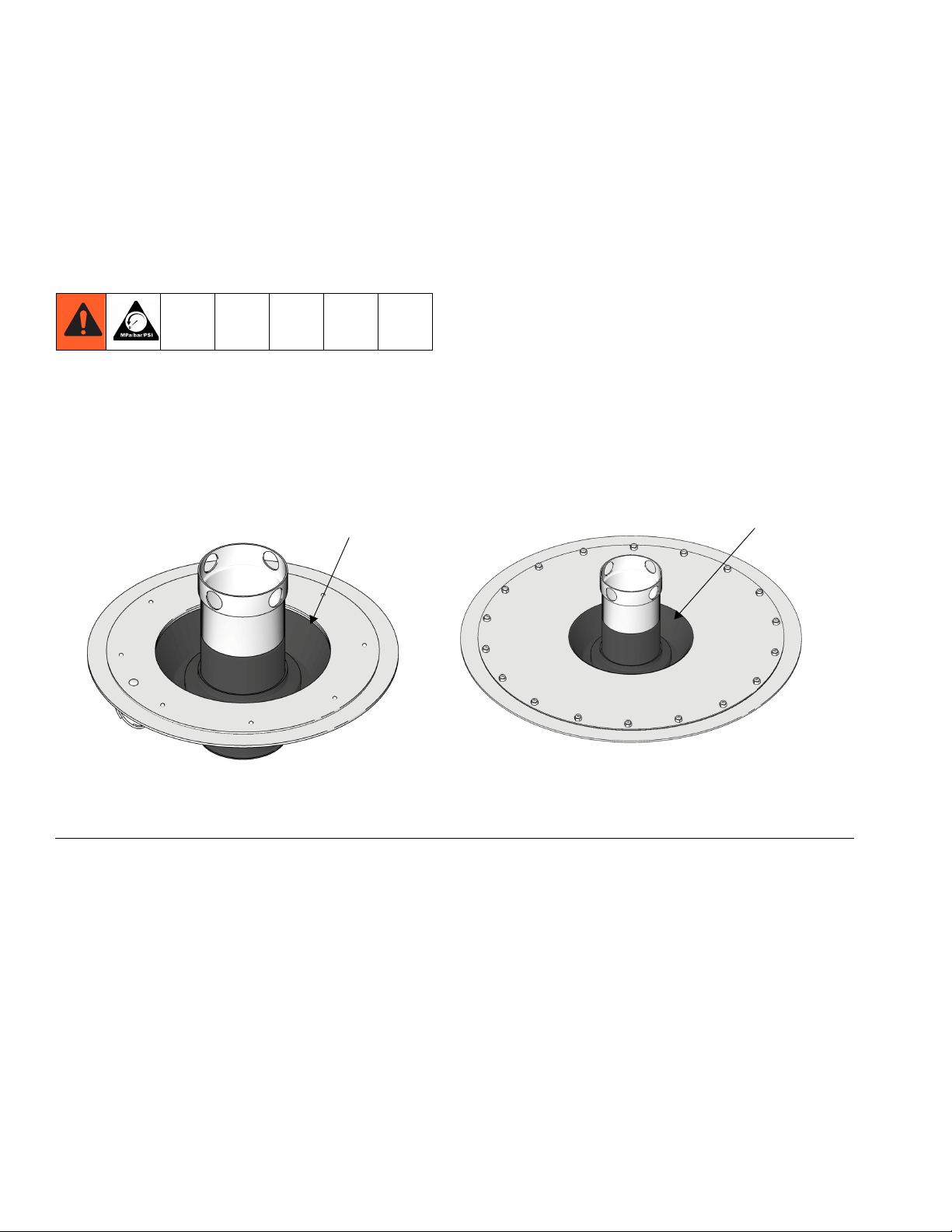
247701 and 77X511 247702 and 77X512
120# Reservoir Follower Plate 400# Reservoir Follower Plate
Follower Plate Installation
Instructions
NOTE: Before the follower plate is installed in the drum
of grease, pack cone with grease.
1. Relieve pressure using the Pressure Relief Procedure in your separate pump manual.
2. Remove pump.
3. Pack grease into follower plate cone (F
IG. 1).
4. Press follower plate, cone side up, into grease and
firmly press on it to remove all air pockets
NOTE: See Parts, page 5 and 6 for illustrations
showing cone side up position.
5. Push down on follower plate cylinder (6) until grease
starts to appear in pump opening at follower plate
grommet (11). See Parts, pages 5 and 6.
6. Reinstall pump and drum cover (See Drum Cover
Installation, page 3).
7. Prime pump.
FIG. 1
2 312738C
Page 3
Drum Cover Installation
126
128
1
6
4
5
3
247704 and 77X515 - 400 pound models
1
3
4
5
247703 and 77X514 - 120 pound model
1
a
6
208
b
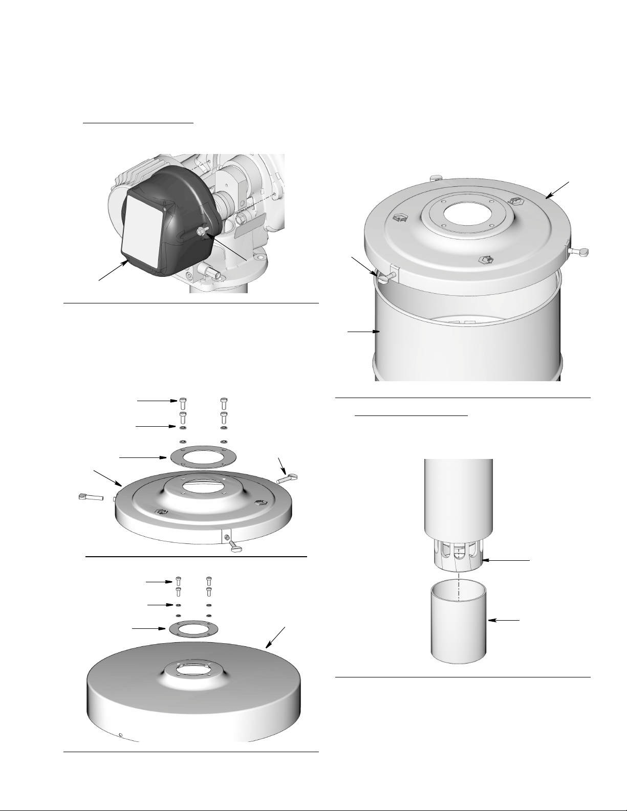
Drum Cover Installation
1. HP and HF Models Only: Remove bolts (128) and
shroud (126) from pump.
FIG. 2
2. Remove screws (4) and washers (5) from drum
cover (1) (F
reused to secure the pump to the drum cover for
reassembly.
IG. 3). Save these parts. They will be
3. Place drum cover (1) on drum (a). For 120 pound
models only, tighten thumb screws (6) securely)
(F
IG. 3).
FIG. 4: 120 Pound Cover Shown
4. HP and HF Models Only:
tective cap (b) from end of pump down tube (208)
(F
IG. 5).
Remove and discard pro-
FIG. 3
312738C 3
FIG. 5
5. Verify gasket (3) is in place on top the drum cover
and laying flat (F
tube through opening in the center of the gasket (3)
and drum cover (1) and into drum.
IG. 3, page 3). Install pump down
Page 4

Drum Cover Installation
4
5
126
128
6. Align holes in pump base with holes in drum cover
(1) (F
IG. 6). Securely fasten pump to drum cover
using screws (4) and washers (5) removed in Step
2, page 3.
FIG. 6
7. HP and HF Models Only:
using bolts (128) (F
IG. 7). Use a wrench to tighten
bolts securely.
FIG. 7
Reinstall shroud (126)
4 312738C
Page 5

Parts
6
7
2
1
11
5
4
10
13
8
9
12
1
3
Part No. 247701 and 77X511, Follower Plate for 120# Reservoirs
Ref.
No. Part No. Description Qty.
1 103833 SCREW, mach, crbh
2 121327 GASKET, cylinder
3 121328 O-RING, 251
4 121329 O-RING, 345
5 15R717 FLANGE, follower plate
6 15R719 CYLINDER, follower plate, upper
7 121209 PLATE, follower (shown cone side
up)
8 183243 WIPER
9 220652 PLATE, wiper
10 15R716 CYLINDER, follower plate, lower
11 186104 GROMMET, follower plate, model
247701
16V328 GROMMET, follower plate, model
77X511
12 108714 PIN, clevis
13 183245 SPRING, retaining
Parts
22
1
1
1
1
1
1
1
1
1
1
1
1
1
312738C 5
Page 6

Parts
6
2
11
3
1
4
10
12
7
5
9
13
8
Part No. 247702 and 77X512, Follower Plate for 400# Reservoirs
Ref.
No. Part No. Description
1 103833 SCREW, mach, crbh
2 121327 GASKET, cylinder
3 121328 O-RING, 251
4 121329 O-RING, 345
5 15R717 FLANGE, follower plate
6 15R719 CYLINDER, follower plate, upper
7 247709 PLATE, follower , upper (shown
cone side up)
8 186463 WIPER, plate, lower
9 161288 RETAINER, barrel
10 15R716 CYLINDER, follower plate, lower
11 186104 GROMMET, follower plate, model
16V328 GROMMET, follower plate, model
12 100377 SCREW, mach, pnh
13 102040 NUT, lock, hex
247702
77X512
Qty
.
14
1
1
1
1
1
1
1
6
1
1
1
18
18
6 312738C
Page 7

Parts
ti1382
1
6
4
5
3
ti1384
1
3
4
5
Part No. 247703 and 77X514
Drum Cover for Dyna-Star 120# Grease Pump
Ref.
No. Part No. Description Qty.
1 COVER, drum
3 15M442 GASKET, pump
100057
4
102962 SCREW, cap, model 77X514
5 100214 WASHER, lock
6 101518 SCREW, thumb
7 070148
SCREW, cap, hex hd, model
247703
STRIP, neoprene, sponge, 3-1/2
ft. (not shown)
Part No. 247704 and 77X515
Drum Cover for Dyna-Star 400# Grease Pump
Ref.
No. Part No. Description Qty.
1
1
4
4
4
1 COVER, drum
3 15M442 GASKET, pump
SCREW, cap, hex hd, model
247704
4
100057
102962 SCREW, cap, model 77X515
5 100214 WASHER, lock
3
1
1
1
4
4
4
312738C 7
Page 8

Graco Information
For the latest information about Graco products, visit www.graco.com.
TO PLACE AN ORDER, contact your Graco distributor or call to identify the nearest distributor.
Phone: 612-623-6928 or Toll Free: 1-800-533-9655, Fax: 612-378-3590
All written and visual data contained in this document reflects the latest product information available at the time of publication.
Graco reserves the right to make changes at any time without notice.
For patent information, see www.graco.com/patents.
Original instructions. This manual contains English. MM 312738
Graco Headquarters: Minneapolis
International Offices: Belgium, China, Japan, Korea
GRACO INC. AND SUBSIDIARIES • P.O. BOX 1441 • MINNEAPOLIS MN 55440-1441 • USA
Copyright 2007, Graco Inc. All Graco manufacturing locations are registered to ISO 9001.
www.graco.com
December 2007, Revised June 2013
 Loading...