

Page 1
Instructions - Parts
™
Fusion
Plural Component, Impingement Mix Air Purge Spray Gun with ClearShot Liquid
Technology. For professional use only.
For use with non-flammable foam and polyurea. Not for use in explosive atmospheres.
3500 psi (24.5 MPa, 245 bar) Maximum Fluid Working Pressure
80-130 psi (0.56-0.9 MPa, 5.6-9.0 bar) Air Inlet Pressure Range
200° F (94° C) Maximum Fluid Temperature
Important Safety Instructions
Read all warnings and instructions in this
manual. Save these instructions.
See page 4 for model information.
CS
312666R
EN
TI11323a
Page 2

Contents
Related Manuals . . . . . . . . . . . . . . . . . . . . . . . . . . . 2
Models/Mix Chamber Selection Guide . . . . . . . . . 3
Round Pattern Guns . . . . . . . . . . . . . . . . . . . . . . 3
Flat Pattern Guns . . . . . . . . . . . . . . . . . . . . . . . . 4
Wide Round Pattern Gun . . . . . . . . . . . . . . . . . . 5
Warnings . . . . . . . . . . . . . . . . . . . . . . . . . . . . . . . . . 6
Overall View . . . . . . . . . . . . . . . . . . . . . . . . . . . . . . . 8
ClearShot Liquid . . . . . . . . . . . . . . . . . . . . . . . . . . . 9
Isocyanate Hazard . . . . . . . . . . . . . . . . . . . . . . . . . . 9
Moisture Sensitivity of Isocyanates . . . . . . . . . . . . 9
Keep Components A and B Separate . . . . . . . . . 10
Foam Resins with 245 fa Blowing Agents . . . . . . 10
Changing Materials . . . . . . . . . . . . . . . . . . . . . . . . 10
Grounding . . . . . . . . . . . . . . . . . . . . . . . . . . . . . . . 11
Piston Safety Lock . . . . . . . . . . . . . . . . . . . . . . . . 11
Remove Front Cover . . . . . . . . . . . . . . . . . . . . . . . 12
Loss of Air Pressure . . . . . . . . . . . . . . . . . . . . . . . 12
Setup . . . . . . . . . . . . . . . . . . . . . . . . . . . . . . . . . . . . 13
Shutdown . . . . . . . . . . . . . . . . . . . . . . . . . . . . . . . . 15
Pressure Relief Procedure . . . . . . . . . . . . . . . . . . 16
Optional Hose Position . . . . . . . . . . . . . . . . . . . . . 17
Flat Spray Tips . . . . . . . . . . . . . . . . . . . . . . . . . . . . 18
Variable Flow . . . . . . . . . . . . . . . . . . . . . . . . . . . . . 19
Operation . . . . . . . . . . . . . . . . . . . . . . . . . . . . . 19
Change Variable Flow Adjustment Knob . . . . . 19
ClearShot Liquid Cartridge Installation/Removal 22
Installation . . . . . . . . . . . . . . . . . . . . . . . . . . . . . 22
Removal . . . . . . . . . . . . . . . . . . . . . . . . . . . . . . 23
Troubleshooting . . . . . . . . . . . . . . . . . . . . . . . . 23
Maintenance . . . . . . . . . . . . . . . . . . . . . . . . . . . . . . 24
Supplied Tool Kit . . . . . . . . . . . . . . . . . . . . . . . . 24
Keep Gun Clean . . . . . . . . . . . . . . . . . . . . . . . . 24
As Needed . . . . . . . . . . . . . . . . . . . . . . . . . . . . 24
Daily . . . . . . . . . . . . . . . . . . . . . . . . . . . . . . . . . 24
Weekly to Monthly . . . . . . . . . . . . . . . . . . . . . . . 24
Flush Gun . . . . . . . . . . . . . . . . . . . . . . . . . . . . . 25
Clean Outside of Gun . . . . . . . . . . . . . . . . . . . . 25
Clean or Replace Front Cover and Retainer . . . 25
Clean Breather Plug . . . . . . . . . . . . . . . . . . . . . 25
Clean Fluid Manifold . . . . . . . . . . . . . . . . . . . . . 26
Adjust Fluid Valve Packings . . . . . . . . . . . . . . . 26
Clean Mix Chamber Nozzle . . . . . . . . . . . . . . . 27
Clean Passages . . . . . . . . . . . . . . . . . . . . . . . . 28
Clean Impingement Ports . . . . . . . . . . . . . . . . . 28
Troubleshooting . . . . . . . . . . . . . . . . . . . . . . . . . . 30
Theory of Operation . . . . . . . . . . . . . . . . . . . . . . . . 33
Cutaway View . . . . . . . . . . . . . . . . . . . . . . . . . . 34
Repair . . . . . . . . . . . . . . . . . . . . . . . . . . . . . . . . . . . 35
Tools Required . . . . . . . . . . . . . . . . . . . . . . . . . 35
Lubrication . . . . . . . . . . . . . . . . . . . . . . . . . . . . . 35
Remove Front End . . . . . . . . . . . . . . . . . . . . . . 35
Attach Front End . . . . . . . . . . . . . . . . . . . . . . . . 36
Mix Chamber and Side Seal Assemblies . . . . . 37
Check Valves . . . . . . . . . . . . . . . . . . . . . . . . . . . 40
Piston . . . . . . . . . . . . . . . . . . . . . . . . . . . . . . . . . 41
Air Valve . . . . . . . . . . . . . . . . . . . . . . . . . . . . . . 42
Parts . . . . . . . . . . . . . . . . . . . . . . . . . . . . . . . . . . . . 43
Mix Chamber Kits . . . . . . . . . . . . . . . . . . . . . . . 48
Flat Tip Kits . . . . . . . . . . . . . . . . . . . . . . . . . . . . 49
O-ring Repair Kits . . . . . . . . . . . . . . . . . . . . . . . 50
Check Valve Filter Screen Kits . . . . . . . . . . . . . 51
Drill Bit Kits . . . . . . . . . . . . . . . . . . . . . . . . . . . . 52
Accessories . . . . . . . . . . . . . . . . . . . . . . . . . . . . . . 54
Stainless Steel Side Seal Kit . . . . . . . . . . . . . . . 54
Polycarballoy Side Seal Kits . . . . . . . . . . . . . . . 54
Flat Pattern Stud Wall Kits . . . . . . . . . . . . . . . . . 54
Gun Cover . . . . . . . . . . . . . . . . . . . . . . . . . . . . . 54
Lubricant for Gun Rebuild . . . . . . . . . . . . . . . . . 54
Grease Cartridge for Gun Shutdown . . . . . . . . . 54
Flushing Manifold . . . . . . . . . . . . . . . . . . . . . . . 54
Fluid Inlet Cover . . . . . . . . . . . . . . . . . . . . . . . . 54
Gun Cleaning Kit . . . . . . . . . . . . . . . . . . . . . . . . 54
ClearShot Liquid Cartridges . . . . . . . . . . . . . . . 54
Solvent Flush Canister Kit . . . . . . . . . . . . . . . . . 55
Solvent Flush Pail Kit . . . . . . . . . . . . . . . . . . . . . 55
Tip Cleanout Tool . . . . . . . . . . . . . . . . . . . . . . . 55
Circulation Manifold . . . . . . . . . . . . . . . . . . . . . . 55
Fusion AP Manifold Adapter . . . . . . . . . . . . . . . 55
Technical Data . . . . . . . . . . . . . . . . . . . . . . . . . . . . 56
Graco Standard Warranty . . . . . . . . . . . . . . . . . . . 57
Graco Information . . . . . . . . . . . . . . . . . . . . . . . . . 57
2 312666R
Page 3
Related Manuals
The following manuals are for accessories
used with the Fusion CS spray gun. Visit
www.graco.com for the most current manual
revisions.
Power-Lock™ Heated Hose
Part Description
309572 Instructions - Parts Manual
(English)
Solvent Flush Kits
Part Description
309963 Instructions - Parts Manual
(English)
Related Manuals
256566 Circulation Manifold Kit
Part Description
313058 Instructions - Parts Manual
(English)
256569 TP100 Kit and 256570 Stud Wall
Foam Kit
Part Description
313121 Instructions - Parts Manual
(English)
256526 Cleanout Tool Kit
Part Description
313129 Instructions - Parts Manual
(English)
312666R 3
Page 4
Models/Mix Chamber Selection Guide
Models/Mix Chamber Selection Guide
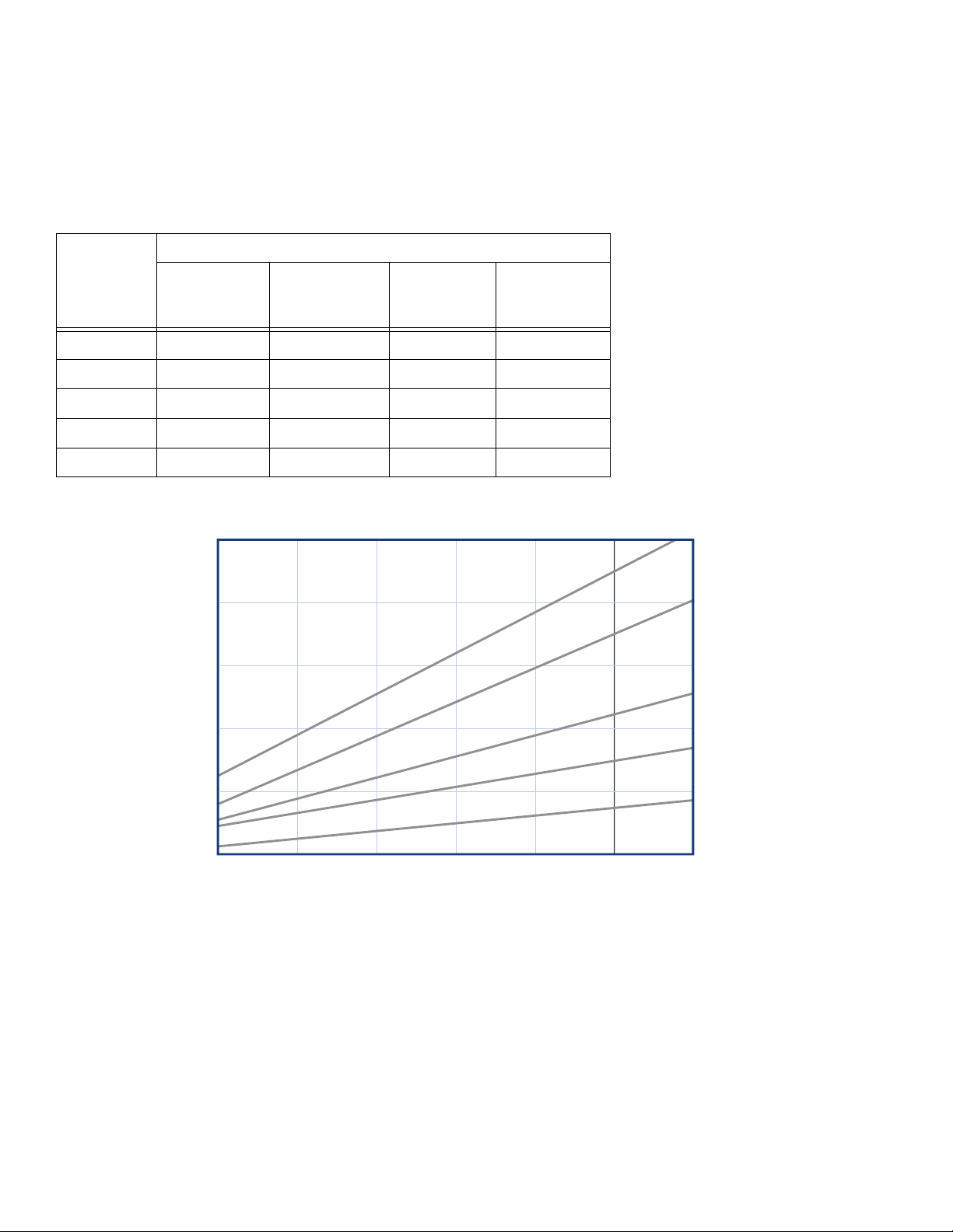
Round Pattern Guns
Mix Chamber
Impingement
Gun Part,
Series Part
CS20RD, B RD2020 0.020 (0.50) -000 SST
CS00RD, B RD0000 0.029 (0.70) -00 SST
CS01RD, B RD0101 0.042 (1.00) -01 SST
CS02RD, B RD0202 0.052 (1.30) -02 SST
CS03RD, B RD0303 0.060 (1.50) -03 SST
Port Size
in. (mm)
Equivalent
Size
Seal
Material
(18.9)
(15.1)
(11.4)
(7.6)
(3.8)
FLOW RATE in gpm (lpm)*
* To calculate flow in lb/min, multiply gpm rate by 10.
Example: 2 gpm x 10 = 20 lb/min.
*Accessory WD (wide pattern) mix chambers are available. See page 49.
5.0
4.0
3.0
2.0
1.0
0
500
(3.5, 35)
1000
(6.9, 69)
3
0
(
3
0
3
0
D
R
2
0
D
R
0
0
0
D
R
D
R
1500
(10.3, 103)
2000
(13.8, 138)
2500
(17.4, 172.4)
PRESSURE in psi (MPa, bar)
3
0
3
0
D
W
)
2
0
2
0
D
W
)
2
0
(
2
0
1*
0
1
0
D
W
)
01
(
01
1
0
D
R
*
0
0
0
0
D
W
)
0
0
(
0
*
2
2
2
2
D
W
)
0
0
0
(
0
2
0
2
3000
(20.7, 207)
3500
(24.1, 241)
4 312666R
Page 5

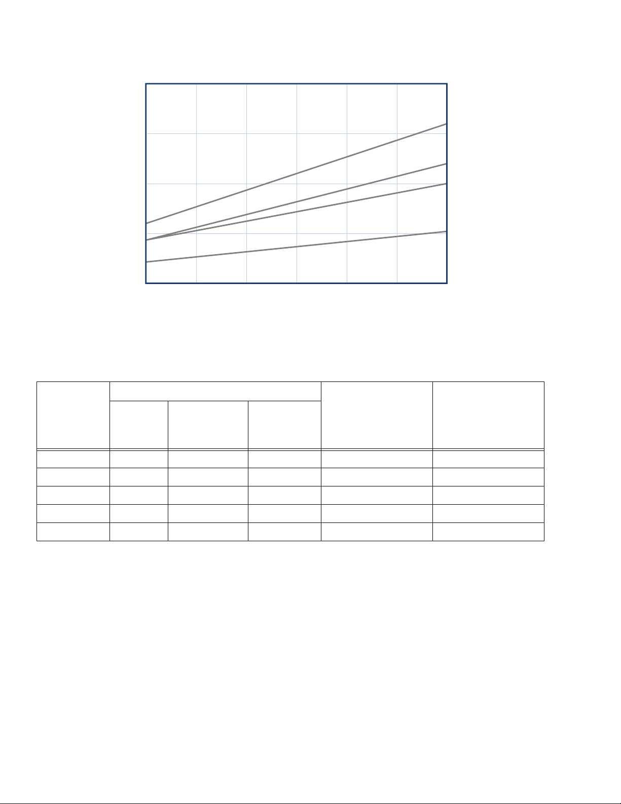
Flat Pattern Guns
Models/Mix Chamber Selection Guide
Mix Chamber Flat Tip
Gun Part,
Series Part
CS20F1, B FL2020 0.020 (0.50) -000 FT0424 8-10 (203-254) 0.024 (0.61)
CS20F2, B FL2020 0.020 (0.50) -000 FT0438 8-10 (203-254) 0.038 (0.97)
CS00F1, B FL0000 0.029 (0.70) -00 FT0424 8-10 (203-254) 0.024 (0.61)
CS00F2, B FL0000 0.029 (0.70) -00 FT0438 8-10 (203-254) 0.038 (0.97)
CS00F3, B FL0000 0.029 (0.70) -00 FT0624 12-14 (305-356) 0.024 (0.61)
CS00F4, B FL0000 0.029 (0.70) -00 FT0638 12-14 (305-356) 0.038 (0.97)
CS00F5, B FL0000 0.029 (0.70) -00 FT0838 16-18 (406-457) 0.038 (0.97)
CS00F6, B FL0000 0.029 (0.70) -00 FT0848 16-18 (406-457) 0.048 (1.22)
CS01F1, B FL0101 0.042 (1.00) -01 FT0424 8-10 (203-254) 0.024 (0.61)
CS01F2, B FL0101 0.042 (1.00) -01 FT0438 8-10 (203-254) 0.038 (0.97)
CS01F3, B FL0101 0.042 (1.00) -01 FT0624 12-14 (305-356) 0.024 (0.61)
CS01F4, B FL0101 0.042 (1.00) -01 FT0638 12-14 (305-356) 0.038 (0.97)
CS01F5, B FL0101 0.042 (1.00) -01 FT0838 16-18 (406-457) 0.038 (0.97)
CS01F6, B FL0101 0.042 (1.00) -01 FT0848 16-18 (406-457) 0.048 (1.22)
CS02F1, B FL0202 0.052 (1.30) -02 FT0424 8-10 (203-254) 0.024 (0.61)
Impingement
Port Size in. (mm)
Equivalent
Size Part
Pattern Size
in. (mm)
Orifice Size
in. (mm)
CS02F2, B FL0202 0.052 (1.30) -02 FT0438 8-10 (203-254) 0.038 (0.97)
CS02F3, B FL0202 0.052 (1.30) -02 FT0624 12-14 (305-356) 0.024 (0.61)
CS02F4, B FL0202 0.052 (1.30) -02 FT0638 12-14 (305-356) 0.038 (0.97)
CS02F5, B FL0202 0.052 (1.30) -02 FT0838 16-18 (406-457) 0.038 (0.97)
CS02F6, B FL0202 0.052 (1.30) -02 FT0848 16-18 (406-457) 0.048 (1.22)
312666R 5
Page 6
Models/Mix Chamber Selection Guide
3.0
(11.4)
2.25
(8.55)
1.5
(5.7)
0.75
(2.85)
FLOW RATE in gpm (lpm)*
* To calculate flow in lb/min, multiply gpm rate by 10.
Example: 2 gpm x 10 = 20 lb/min.
0
500
(3.5, 35)
(6.9, 69)
1000
L
F
L
F
F
1500
(10.3, 103)
2000
(13.8, 138)
2500
(17.4, 172.4)
PRESSURE in psi (MPa, bar)
2
0
L
F
0
0
2
L
i
w
2
0
1
0
1
0
w
0
0
w
0
2
0
(20.7, 207)
h
t
w
t
i
i
T
F
h
t
i
F
h
F
th
3000
X
T
F
X
T
8
4
X
X
T
3
X
X
X
p
i
t
i
t
8
3
X
p
i
t
8
p
ti
4
2
(24.1, 241)
p
3500
Wide Round Pattern Gun
Mix Chamber
Impingement
Gun Part,
Series Part
Port Size
in. (mm)
Equivalent
Size
CS22WD, B WD2222 0.022 (0.56) N/A 8-9 (203-229) 4.5 lb/min at 1000 psi
CS00WD, B WD0000 0.028 (0.71) -00 15 (381.0) RD0000
CS01WD, B WD0101 0.039 (0.99) -01 16 (406.4) RD0101
CS02WD, B WD0202 0.046 (1.17) -02 18 (457.2) RD0202
CS03WD, B WD0303 0.057 (1.45) -03 18 (457.2) RD0303
Pattern Diameter at
24 in. (610 mm) to
Target
in. (mm)
Equivalent Flow to
Mix Chamber Size
Reference Part No.
6 312666R
Page 7
Warnings
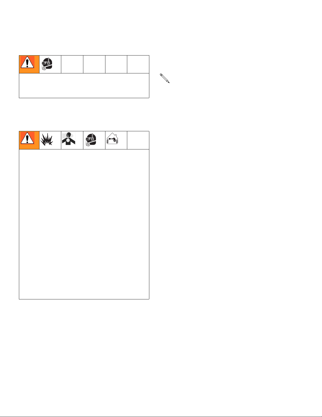
Warnings
The following warnings are for the setup, use, grounding, maintenance, and repair of this equipment. The exclamation point symbol alerts you to a general warning and the hazard symbol refers
to procedure-specific risk. Refer back to these warnings. Additional, product-specific warnings
may be found throughout the body of this manual where applicable.
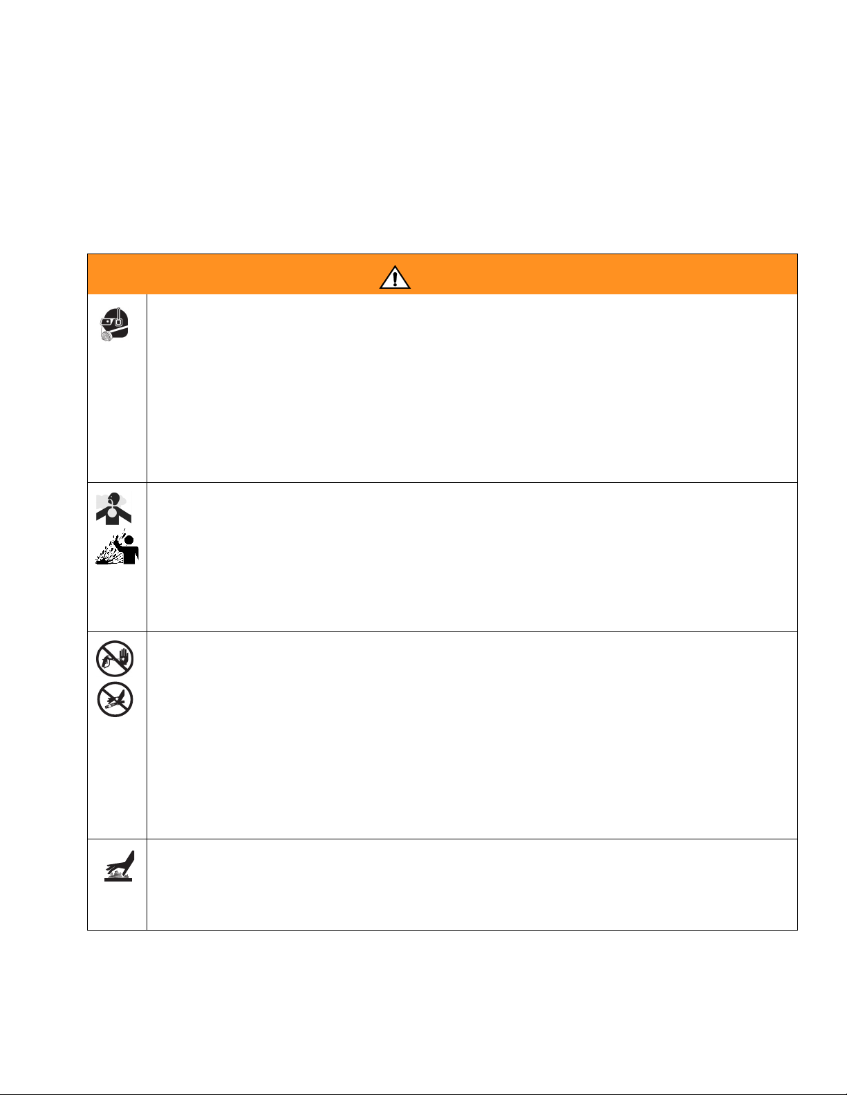
WARNING
PERSONAL PROTECTIVE EQUIPMENT
You must wear appropriate protective equipment when operating, servicing, or when in
the operating area of the equipment to help protect you from serious injury, including
eye injury, inhalation of toxic fumes, burns, and hearing loss. This equipment includes
but is not limited to:
• Protective eyewear
• Clothing and respirator as recommended by the fluid and solvent manufacturer
•Gloves
• Hearing protection
TOXIC FLUID OR FUMES HAZARD
Toxic fluids or fumes can cause serious injury or death if splashed in the eyes or on
skin, inhaled, or swallowed.
• Read MSDS’s to know the specific hazards of the fluids you are using.
• Store hazardous fluid in approved containers, and dispose of it according to applicable guidelines.
• Always wear impervious gloves when spraying or cleaning equipment.
SKIN INJECTION HAZARD
High-pressure fluid from gun, hose leaks, or ruptured components will pierce skin. This
may look like just a cut, but it is a serious injury that can result in amputation. Get
immediate surgical treatment.
• Do not point gun at anyone or at any part of the body.
• Do not put your hand over the spray tip.
• Do not stop or deflect leaks with your hand, body, glove, or rag.
• Engage trigger lock when not spraying.
• Follow Pressure Relief Procedure in this manual, when you stop spraying and
before cleaning, checking, or servicing equipment.
BURN HAZARD
Equipment surfaces and fluid that’s heated can become very hot during operation. To
avoid severe burns, do not touch hot fluid or equipment. Wait until equipment/fluid has
cooled completely.
312666R 7
Page 8
Warnings
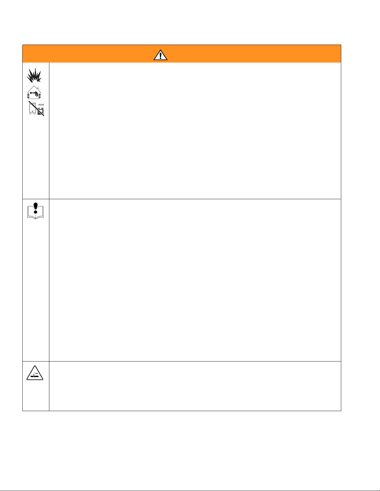
WARNING
FIRE AND EXPLOSION HAZARD
Flammable fumes, such as solvent and paint fumes, in work area can ignite or
explode. To help prevent fire and explosion:
• Use equipment only in well ventilated area.
• Eliminate all ignition sources; such as pilot lights, cigarettes, portable electric
lamps, and plastic drop cloths (potential static arc).
• Keep work area free of debris, including solvent, rags and gasoline.
• Do not plug or unplug power cords, or turn power or light switches on or off when
flammable fumes are present.
• Ground all equipment in the work area. See Grounding instructions.
• Use only grounded hoses.
• Hold gun firmly to side of grounded pail when triggering into pail.
• If there is static sparking or you feel a shock, stop operation immediately. Do not
use equipment until you identify and correct the problem.
• Keep a working fire extinguisher in the work area.
EQUIPMENT MISUSE HAZARD
Misuse can cause death or serious injury.
• Do not operate the unit when fatigued or under the influence of drugs or alcohol.
• Do not exceed the maximum working pressure or temperature rating of the lowest
rated system component. See Technical Data in all equipment manuals.
• Use fluids and solvents that are compatible with equipment wetted parts. See Tech-
nical Data in all equipment manuals. Read fluid and solvent manufacturer’s warnings. For complete information about your material, request MSDS forms from
distributor or retailer.
• Check equipment daily. Repair or replace worn or damaged parts immediately with
genuine manufacturer’s replacement parts only.
• Do not alter or modify equipment.
• Use equipment only for its intended purpose. Call your distributor for information.
• Route hoses and cables away from traffic areas, sharp edges, moving parts, and
hot surfaces.
• Do not kink or over bend hoses or use hoses to pull equipment.
• Keep children and animals away from work area.
• Comply with all applicable safety regulations.
PRESSURIZED ALUMINUM PARTS HAZARD
Do not use 1,1,1-trichloroethane, methylene chloride, other halogenated hydrocarbon
solvents or fluids containing such solvents in pressurized aluminum equipment. Such
use can cause serious chemical reaction and equipment rupture, and result in death,
serious injury, and property damage.
8 312666R
Page 9
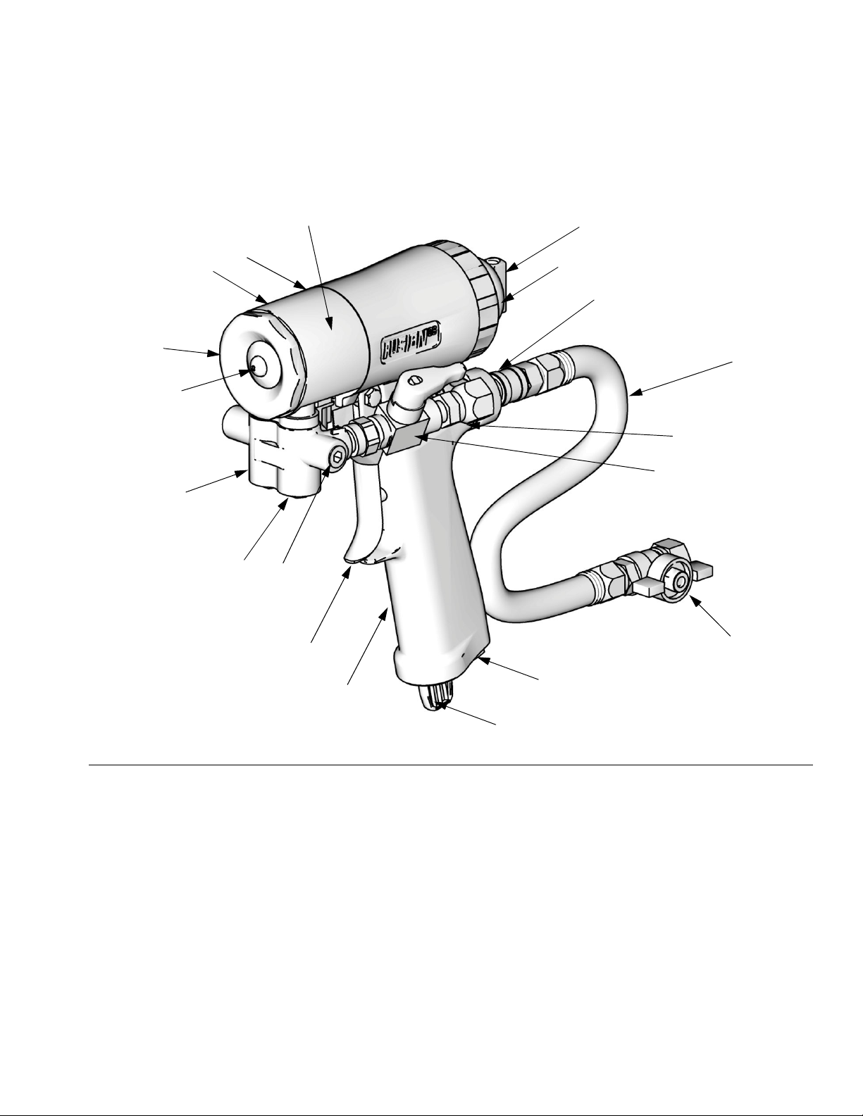
Overall View
Overall View
C
N
M
U
Y
G
L
F
X
D
V
S
A
P
T
H
FIG. 1
Key:
A A Side Fluid Valve (ISO)
B B Side Fluid Valve (RESIN) (not shown)
C Front Cover Retainer
D Air Line Quick Coupler
E Breather Plug
F Fluid Housing (under cover)
G Grease Fitting (under cover)
H Handle
L Piston Safety Lock/Flow Selector Knob
M Gun Fluid Manifold
N Mix Chamber Nozzle
P Optional Fluid Inlets (A Side Shown)
W
E
TI11324a
R
R ClearShot Liquid Cartridge
S Fluid Inlet Swivels (A Side Shown)
T Trigger
U Front Cover
V Gun Air Whip Hose
WAir Valve
X Variable Flow Adjustment Knob
Y Manifold Check Valve/Inlet Screen Housing
312666R 9
Page 10
ClearShot Liquid
ClearShot Liquid
Read material MSDS to know specific hazards and precautions related to ClearShot
Liquid.
Isocyanate Hazard
Spraying materials containing isocyanates
creates potentially harmful mists, vapors,
and atomized particulates.
Read material manufacturer’s warnings and
material MSDS to know specific hazards and
precautions related to isocyanates.
Prevent inhalation of isocyanate mists,
vapors, and atomized particulates by providing sufficient ventilation in the work area. If
sufficient ventilation is not available, a supplied-air respirator is required for everyone in
the work area.
To prevent contact with isocyanates, appropriate personal protective equipment, including chemically impermeable gloves, boots,
aprons, and goggles, is also required for
everyone in the work area.
begin to gel, increasing in viscosity. If used,
this partially cured ISO will reduce performance and the life of all wetted parts.
The amount of film formation and rate of
crystallization varies depending on the
blend of ISO, the humidity, and the temperature.
To prevent exposing ISO to moisture:
• Always use a sealed container with a desiccant dryer in the vent, or a nitrogen atmosphere. Never store ISO in an open
container.
• Keep the ISO lube pump reservoir filled
with Graco Throat Seal Liquid (TSL), Part
206995. The lubricant creates a barrier
between the ISO and the atmosphere.
• Use moisture-proof hoses specifically
designed for ISO, such as those supplied
with your system.
• Never use reclaimed solvents, which may
contain moisture. Always keep solvent containers closed when not in use.
• Never use solvent on one side if it has
been contaminated from the other side.
• Always park pumps when you shutdown.
• Always lubricate threaded parts with Part
217374 ISO pump oil or grease when reassembling.
Moisture Sensitivity of Isocyanates
Isocyanates (ISO) are catalysts used in two
component foam and polyurea coatings. ISO
will react with moisture (such as humidity) to
form small, hard, abrasive crystals, which
become suspended in the fluid. Eventually a
film will form on the surface and the ISO will
10 312666R
Page 11

Keep Components A and B Separate
Keep Components A
and B Separate
CAUTION
To prevent cross-contamination of the equipment’s wetted parts, never interchange com-
ponent A (isocyanate) and component B
(resin) parts. The gun is shipped with the A
side on the left. The fluid manifold, fluid
housing, side seal assembly, check valve
cartridge, and mix chamber are marked on
the A side.
Foam Resins with 245 fa Blowing Agents
New foam blowing agents will froth at temperatures above 90°F (33°C) when not under pressure, especially if agitated. To reduce frothing,
minimize preheating in a circulation system.
Changing Materials
• When changing materials, flush the equipment multiple times to ensure it is thoroughly clean.
• Always clean the fluid inlet strainers after
flushing.
• Check with your material manufacturer for
chemical compatibility.
• Most materials use ISO on the A side, but
some use ISO on the B side.
• Epoxies often have amines on the B (hardener) side. Polyureas often have amines on
the B (resin) side.
312666R 11
Page 12
Grounding
Grounding
Check your local electrical code and proportioner manual for detailed grounding instructions.
Ground the spray gun through connection to a
Graco-approved grounded fluid supply hose.
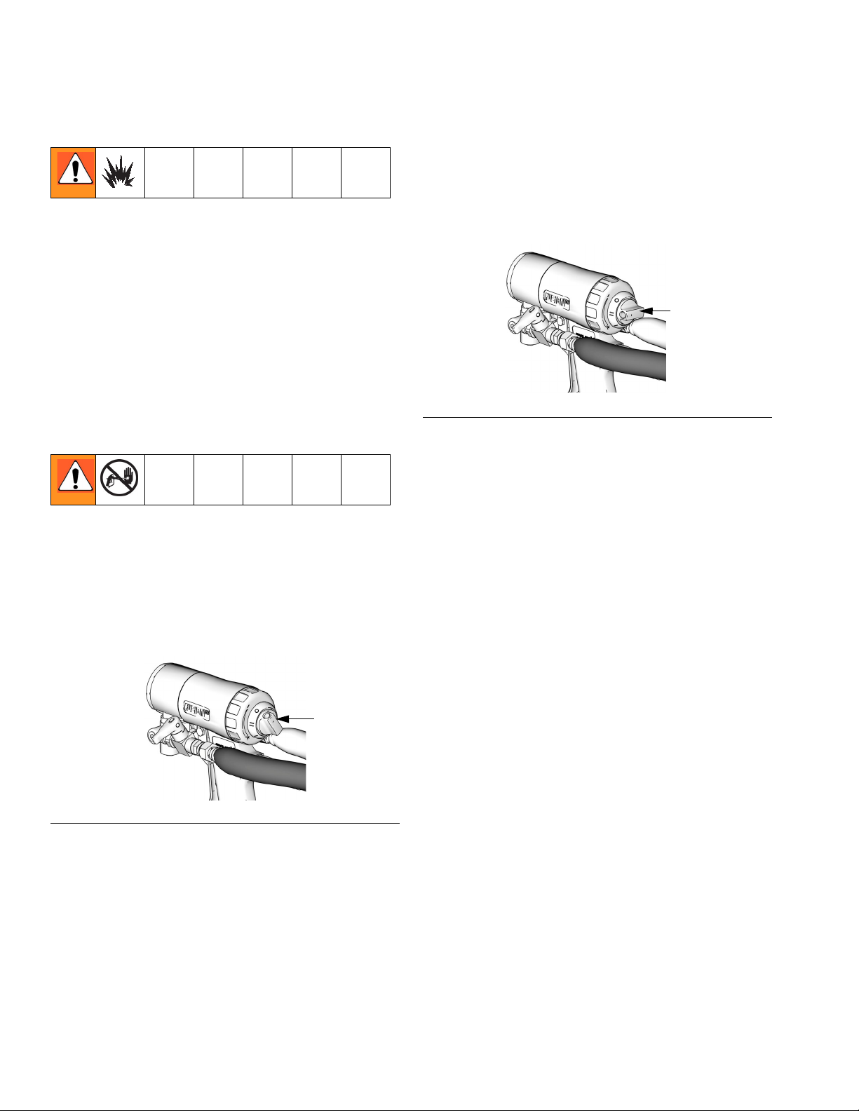
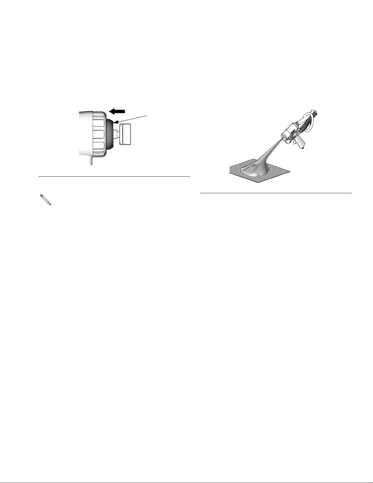
Piston Safety Lock
Engage piston safety lock whenever you stop
spraying to avoid accidental triggering.
Disengage
To disengage piston safety lock, push knob in
and turn counterclockwise until it pops out.
There will be a gap between knob and gun
body.
Disengaged
TI12240a
FIG. 3
Engage
To engage piston safety lock, push knob in
and turn clockwise. If engaged, gun will not
actuate.
Engaged
TI11326a
FIG. 2
12 312666R
Page 13
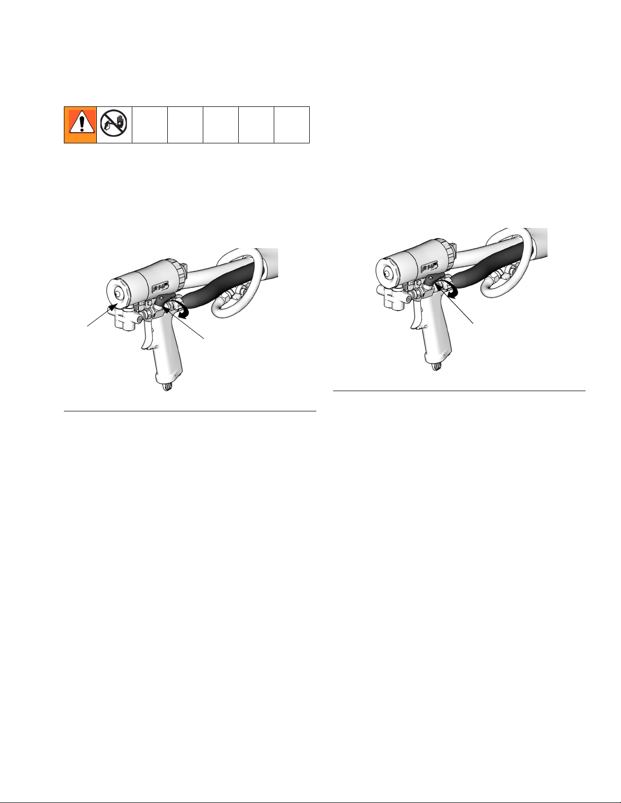
Remove Front Cover
Remove Front Cover
1. Follow Pressure Relief Procedure, page
17.
2. Ensure fluid valves A and B are closed
before turning front cover retainer (C).
C
A
Loss of Air Pressure
In event of loss of air pressure, gun will continue to spray. To shut off gun, do one of the
following:
• Push in piston safety lock, see page 12.
• Close fluid valves A and B.
A
TI11327a
FIG. 4
TI11327a
FIG. 5
312666R 13
Page 14
Setup
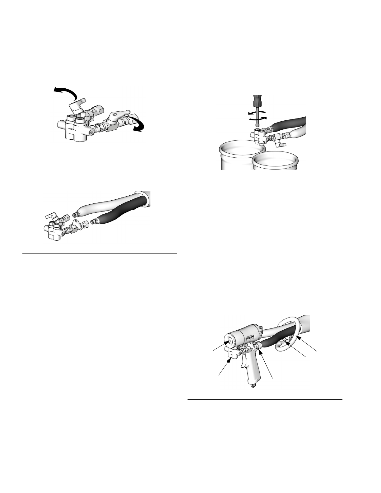
Setup
1. Close fluid valves A and B.
TI11328a
FIG. 6
2. Connect A (ISO) and B (RESIN) fluid hoses
to fluid manifold.
TI11329a
FIG. 7
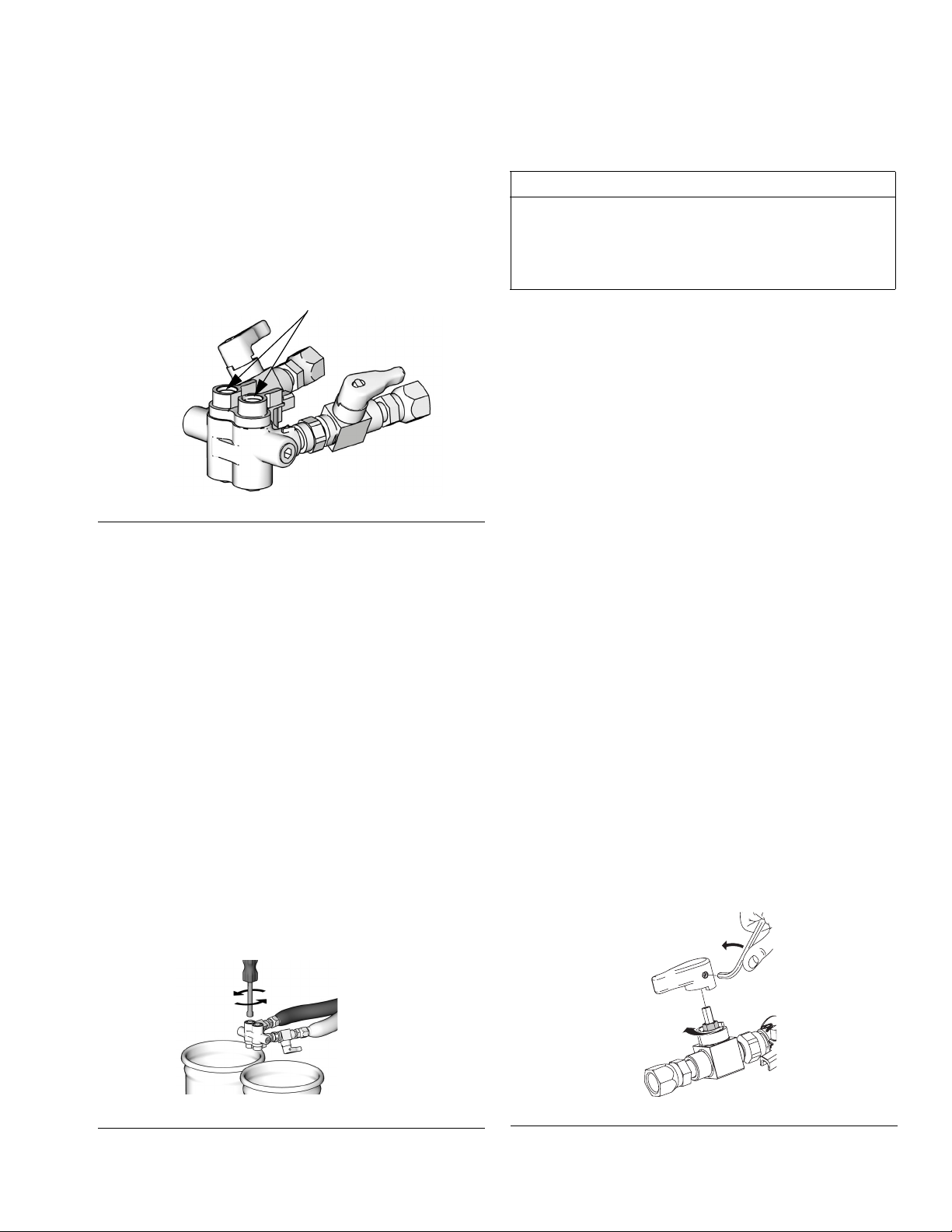
3. Purge air from fluid lines using feed pump
pressure only (less than 500 psi (3.5 MPa,
35 bar)).
a. Ensure fluid valves are closed. Open
fluid manifold check valves 2 to 2-1/2
turns.
c. Close fluid valves and retighten fluid
manifold check valves.
TI11337a
FIG. 8
4. Engage piston safety lock, page 12.
5. Install ClearShot Liquid cartridge. See
ClearShot Liquid Cartridge Installation/Removal , page 23.
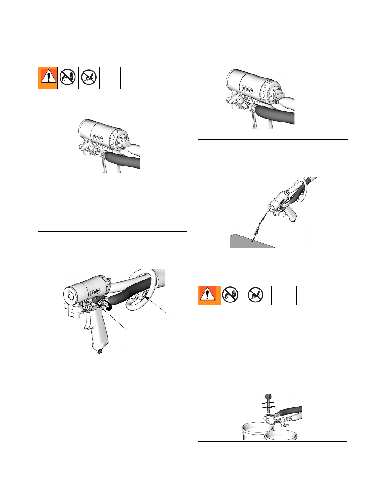
6. Connect gun air whip hose (V) air valve (W)
to main air hose. Assemble fluid manifold
(M) to gun by hand, and then tighten bolt.
7. Connect air line to quick coupler (D). Turn
on air. Open air valve (W). Air should flow
from nozzle (N).
b. Open fluid valves and wait for all air to
bleed from fluid hoses.
N
M
D
V
W
TI11331a
FIG. 9
8. Apply layer of lubricant over front cover of
gun and front cover retainer, or use gun
cover to prevent overspray buildup and
ease disassembly.
14 312666R
Page 15
Setup
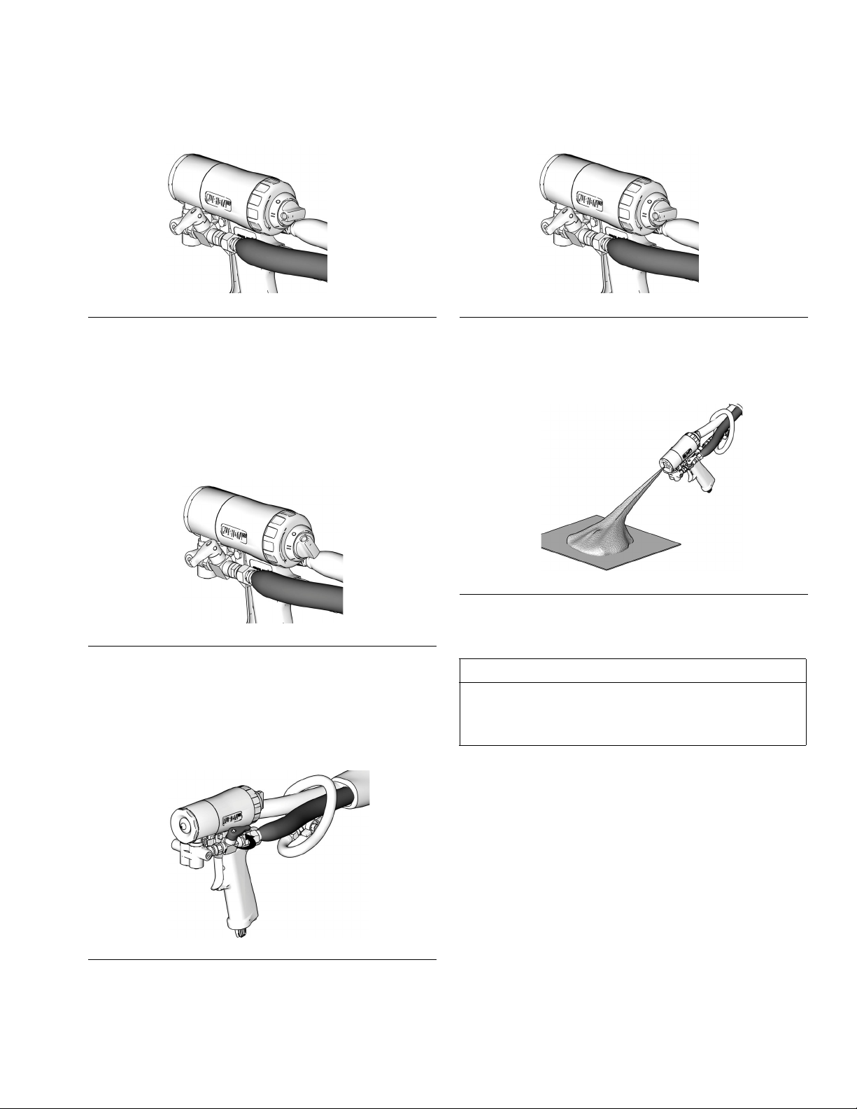
9. Disengage piston safety lock, page 12.
TI12240a
FIG. 10
10.Trigger gun to check for full mix chamber
travel and to prime ClearShot Liquid dosing
pump. See ClearShot Liquid Cartridge
Installation/Removal, page 23.
11.Engage piston safety lock, page 12.
14.Disengage piston safety lock, page 12.
TI12240a
FIG. 13
15.Test spray onto cardboard. Adjust pressure
and temperature to get desired results.
TI11326a
FIG. 11
12.Turn on proportioner.
13. Open B (RESIN) fluid valve. Then open A
(ISO) fluid valve.
TI11333a
FIG. 12
TI11334a
FIG. 14
16.The gun is now ready to spray.
CAUTION
Air supply is required for gun actuation. Do
not disconnect gun air supply until fluid pressure is relieved, page 17.
312666R 15
Page 16
Shutdown
Shutdown
Overnight Shutdown
1. Follow Pressure Relief Procedure, page
17.
2. Leave air turned on and gun detriggered.
Grease gun daily to prevent two-component curing and keep fluid passages clean.
Purge air carries grease mist through air
chamber (AC), impingement ports (IP),
and out mix chamber nozzle (N), coating
all surfaces. Use Graco 117773 grease.
N
IP
AC
14
3. Unscrew and remove front cover retainer
(C). Remove front cover (U).
4. Using grease gun, dispense a half shot of
grease into fitting (G). Do not over-grease;
use a half shot maximum.
G
N
U
W
C
TI11335a
FIG. 16
5. Replace front cover (U) and front cover
retainer (C).
FIG. 15
Always leave a ClearShot Liquid cartridge
in gun handle to prevent cartridge bore
contamination.
!IR
#3,
#3,!IR
&LUID
'REASE
TI12124a
16 312666R
Page 17
Pressure Relief Procedure
1. Engage piston safety lock, page 12.
FIG. 19
4. Trigger gun onto cardboard or into waste
TI11326a
FIG. 17
Pressure Relief Procedure
TI12240a
container to relieve pressure.
CAUTION
Air supply is required for gun actuation. Do
not disconnect gun air supply until fluid pressure is relieved.
2. Close fluid valves A and B. Leave air valve
(W) open.
W
A
TI11327a
IG
. 18
F
3. Disengage piston safety lock, page 12.
TI11336a
FIG. 20
5. Engage piston safety lock, page 12.
Fluid in the hose and proportioner is still under
pressure. Follow the Pressure Relief Procedure
in the proportioner manual.
To relieve pressure in the hose manifold after the
gun is removed, place the fluid manifold over
containers, facing away from you. Ensure fluid
valves are closed. Very slowly open fluid manifold check valves 2 to 2-1/2 turn. Under high
pressure, fluid will spray sideways from the fluid
ports.
TI11337a
312666R 17
Page 18
Optional Hose Position
Optional Hose Position
Fluid inlet swivel fittings point to rear. If
desired, these positions can be changed so
hoses point downward.
CAUTION
To prevent cross-contamination of gun’s wetted parts, do not interchange A component
(isocyanate) and B component (resin) parts.
1. Follow Pressure Relief Procedure, page
17. Also relieve system pressure, see proportioner manual.
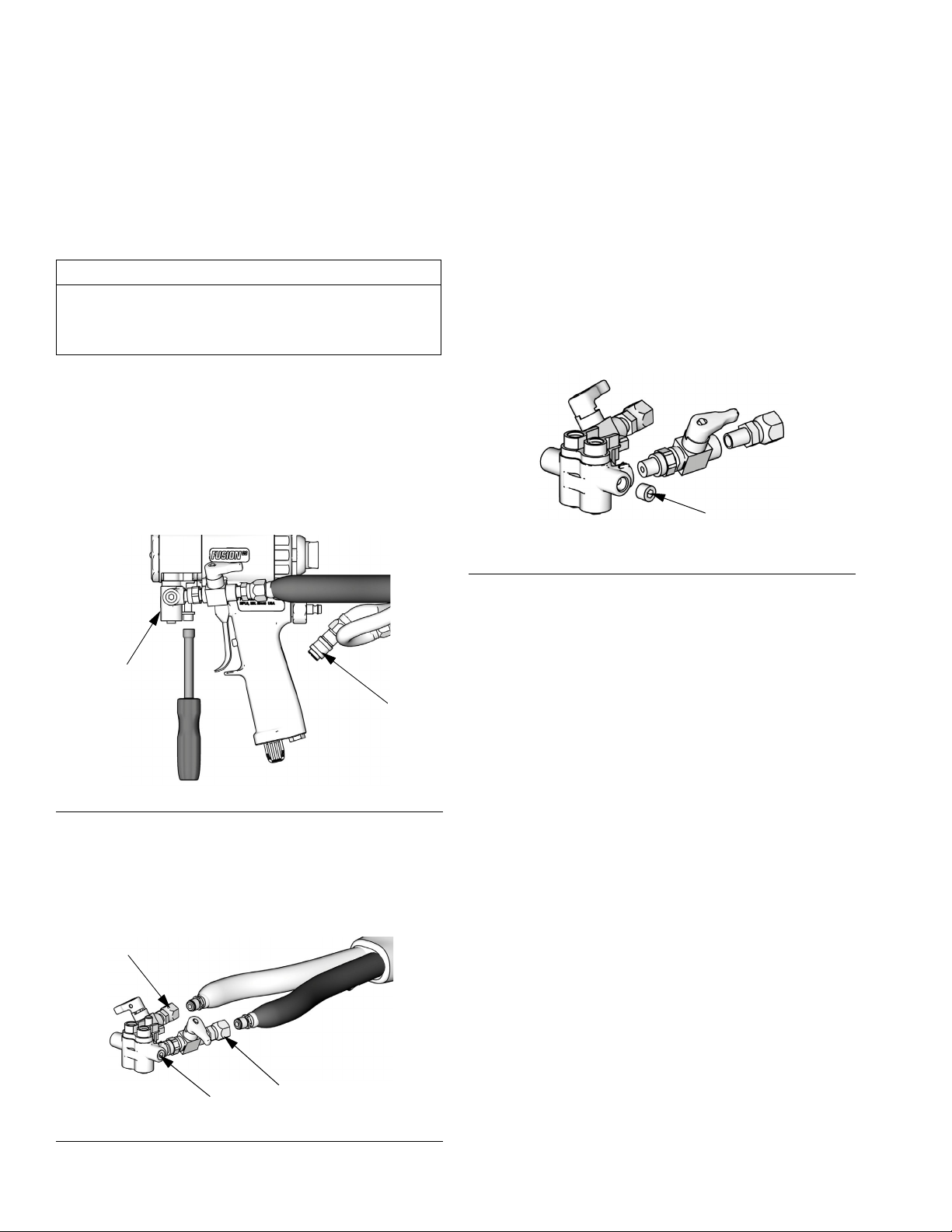
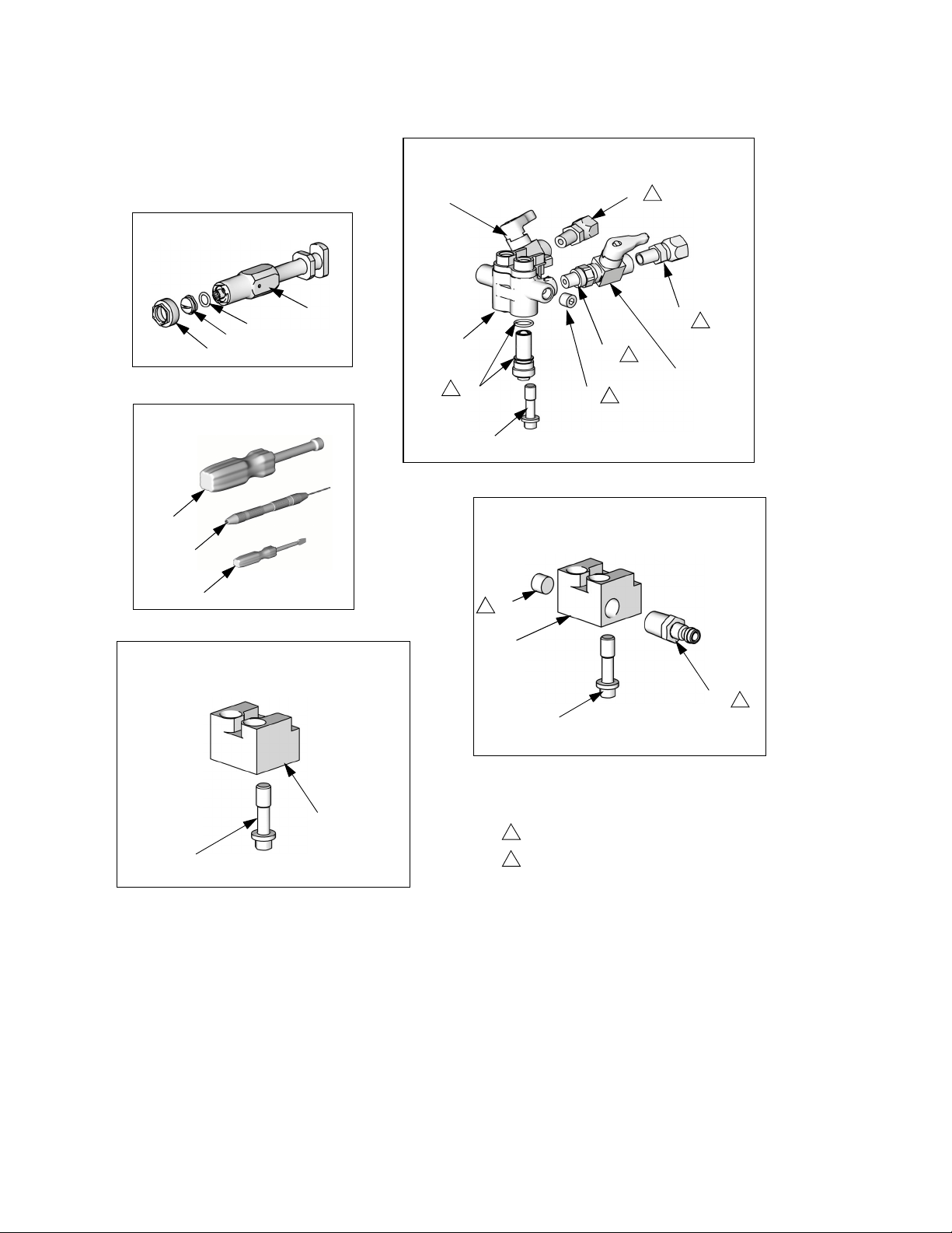
2. Disconnect air (D) and remove fluid manifold (M).
4. Apply thread sealant to plugs (1e), elbows
(35), and male threads of fluid valve
assemblies. Install elbows (35) in optional
inlets, facing down. Install fluid valve
assemblies in elbows. Be sure to install A
fluid assembly in A side. Install plugs where
swivels had been. Torque all parts to
235-245 in-lb (26.6-27.7 N•m).
1e
TI12085a
FIG. 23
5. Connect A and B hoses to A and B swivels.
M
D
TI11330a
IG
. 21
F
3. Disconnect fluid hoses from inlet swivels
(A, B). Remove fluid valve assemblies.
Remove plugs from optional inlets (P).
B
P
A
TI11329a
FIG. 22
6. Attach fluid manifold. Connect air. Return
gun to service.
18 312666R
Page 19

Flat Spray Tips
Flat Spray Tips
1. Follow Pressure Relief Procedure, page
17.
2. Unscrew and remove front cover retainer
(C).
3. Remove front cover (U) and o-ring (2b).
Inspect o-ring.
4. Remove tip retainer (46) and tip (21).
Inspect o-ring (47).
5. Remove fluid housing (F). Loosen A and B
side seals. Slide flat mix chamber (14) out
rear of fluid housing.
47
21
14
c. Assemble o-ring (47), tip (21), and tip
retainer (46) to front of mix chamber
(14).
8. Reposition tip horizontally or vertically, or
install different tip size.
TI12088a
46
U
C
F
TI12087a
FIG. 24
If tip is stuck, pry off with small screwdriver
or pull off with pliers. Tip is hardened to
resist damage.
6. To clean, soak tip in compatible solvent.
Clean gently with tip cleanout tool 15D234;
page 56 for details of tool.
7. Reassemble in reverse order.
a. Insert mix chamber (14) from rear of
fluid housing.
b. Tighten A and B side seals on fluid
housing.
TI2648a
FIG. 25
Tips marked on back with last three digits
of part number. See Flat Tip Kits, page
50.
9. Reinstall fluid housing (F) to handle.
10.Reinstall front cover (U) and front cover
retainer (C).
312666R 19
Page 20
Variable Flow
Variable Flow
Operation
The variable flow feature is designed to
provide immediate adjustment between a
full flow pattern (determined by mix chamber size) and a user defined reduced flow
pattern.
Variable
Flow
Adjustment
Knob
FIG. 26
TI12240a
Safety
Stop/Flow
Selector
Knob
Change Variable Flow Adjustment Knob
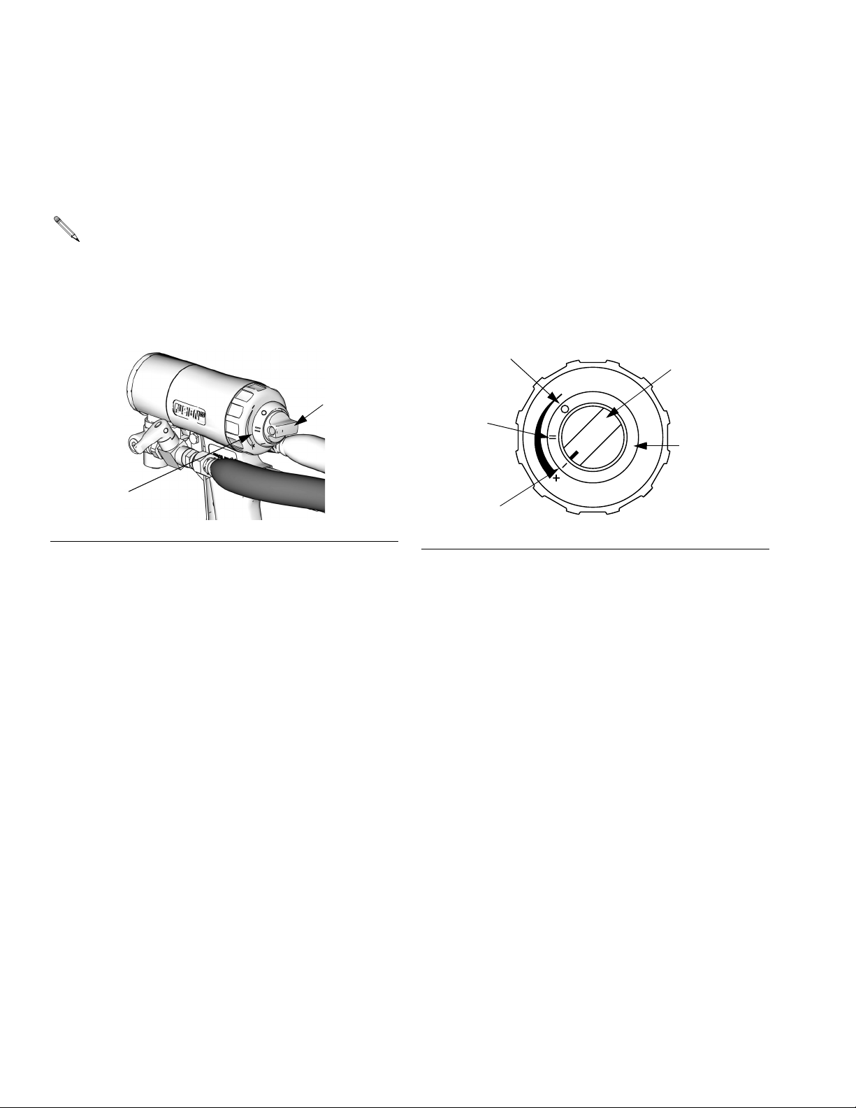
1. Turn air valve (W) OFF.
2. Turn flow selector knob to variable flow
position. See FIG. 27.
OFF
Full Flow
Variable
Flow
FIG. 27
Safety
Stop/Flow
Selector
Knob
Variable
Flow
Adjustment
Knob
TI11345a
Reduced Flow
To spray a reduced flow pattern, push in and
turn flow selector knob to variable flow position. See FIG. 27.
Full Flow
To return to a full flow pattern, push in and turn
flow selector knob to full flow position. See FIG.
27.
20 312666R
Page 21
3.
To increase variable flow
: push in and turn
variable flow knob counterclockwise.
To decrease variable flow
: push in and turn
variable flow knob clockwise.
Variable
Flow
Adjustment
Knob
TI11344a
FIG. 28
The variable flow adjustment knob cannot
be adjusted when the flow selector knob is
in the safety stop position. See FIG. 27.
Variable Flow
4. Turn air valve ON, and open fluid valves.
Verify that flow selector knob is set to the
variable flow position. See FIG. 27.
5. Test spray pattern on cardboard. Repeat
steps 1 through 6 until desired spray pattern is reached.
TI11334a
FIG. 29
The variable flow adjustment knob locks
into detents every 15°. Ensure knob is
locked into a detent before proceeding to
step 5.
312666R 21
Page 22

Variable Flow
22 312666R
Page 23

ClearShot Liquid Cartridge Installation/Removal
ClearShot Liquid Cartridge Installation/Removal
If ClearShot Liquid cartridge removal or
installation is difficult, lubricate cartridge
o-rings and/or cartridge bore with a few
drops of ClearShot Liquid. Water-based
lubricants can be used as well.
Do not use Fusion grease or other petroleum- or vegetable-based lubricants. They
will cause cartridge o-rings to swell and
stick inside gun handle.
Installation
1. Follow Pressure Relief Procedure, page
17.
2. Remove plastic cap from new ClearShot
Liquid cartridge.
3. Insert cartridge into gun handle. Ensure
cartridge tabs are aligned correctly with
cartridge tab recesses in gun handle.
TI113341a
FIG. 31
4. After cartridge is fully inserted, turn cartridge 1/4 turn clockwise to lock it into gun
handle.
TI113342a
FIG. 32
TI113340a
IG
. 30
F
5. Turn air valve ON and prime ClearShot Liquid dosing pump.
a. Trigger gun 20 times to prime dosing
pump.
b. Trigger gun onto cardboard to see
dosed ClearShot Liquid.
6. Resume spraying.
312666R 23
Page 24

ClearShot Liquid Cartridge Installation/Removal
Removal
1. Follow Pressure Relief Procedure, page
17.
2. Turn air valve (W) OFF.
3. Push in and turn cartridge 1/4 turn counterclockwise (viewed from bottom).
TI11338a
FIG. 33
Troubleshooting
For ClearShot Liquid cartridge troubleshooting,
see Troubleshooting on page 31.
4. Pull cartridge out of gun handle.
TI11339a
FIG. 34
24 312666R
Page 25

Maintenance
Maintenance
Supplied Tool Kit
• Hex Nut Driver; 5/16
• Screwdriver; 1/8 blade
• Nozzle Drill Bit; various sizes depending on
nozzle size. See Table 1.
• Impingement Port Drill Bit; various sizes
depending on port size. See Table 3.
• 117661 Pin Vise; dual reversible chucks
Reversible
Reversible
TI3684a
FIG. 35
As Needed
1. Clean Outside of Gun, page 26.
2. Clean Mix Chamber Nozzle, page 28, a
minimum of once a day.
3. Clean Breather Plug, page 26.
4. Clean Fluid Manifold, page 27.
5. Clean Passages, page 29.
6. Clean Impingement Ports, page 29.
7. Adjust Fluid Valve Packings, page 27.
Daily
Follow Shutdown, page 16.
Weekly to Monthly
• 117792 Grease Gun; with 3 oz grease
• 15B817 Flush Manifold
Keep Gun Clean
Keep gun clean with accessory gun cover,
page 55.
Applying a light coat of lubricant will make
cleaning easier.
1. Clean Mix Chamber and Side Seal
Assemblies, page 38. Check o-rings.
2. Clean Check Valves, page 41. Check
o-rings and filters.
312666R 25
Page 26

Maintenance
Flush Gun
1. Follow Pressure Relief Procedure, page
17.
2. Flush with compatible solvent into a
grounded metal pail, holding a metal part of
fluid manifold firmly to side of pail. Use lowest possible fluid pressure when flushing.
3. Follow Pressure Relief Procedure, page
17.
For a more thorough flush, a solvent flush
kit (256510 248229) is available as an
accessory.
Clean Outside of Gun
Wipe off outside of gun with compatible solvent. Use N-Methylpyrrolidone (NMP), Dynasolve CU-6, Dzolv, or an equivalent to soften
cured material.
CAUTION
These solvents are not recommended for
flushing; use only for cleaning.
Clean or Replace Front Cover and Retainer
Soak front cover retainer (C) and front cover
(U) in compatible solvent. Brush or wipe clean.
Replace as needed.
Clean Breather Plug
Remove and clean breather plug with compatible solvent.
26 312666R
Page 27
Maintenance
Clean Fluid Manifold
Clean fluid manifold fluid ports with compatible
solvent and brush whenever removed from
gun. Do not damage the internal sealing surfaces. Fill fluid ports with grease if left
exposed, to seal out moisture.
Fluid Ports
TI12089a
FIG. 36:
Clean or Replace Fluid Screens
1. Follow Pressure Relief Procedure, page
17.
3. Remove fluid screens by unthreading them
from fluid manifold.
CAUTION
To prevent cross-contamination of the check
valves, do not interchange A component and
B component parts. The A component check
valve is marked with an A.
4. Clean or replace fluid screens. See Acces-
sories, page 55.
5. Carefully inspect o-rings and fluid screen
surfaces. Replace if worn or damaged.
6. Liberally lubricate o-rings and reassemble.
Use a hex nut driver to tighten.
Adjust Fluid Valve Packings
Periodic adjustment may be necessary to stop
fluid leakage. If fluid valve is leaking, adjust the
packings:
2. Relieve pressure in hose manifold after gun
is removed.
a. Place the fluid manifold over containers,
facing away from you.
b. Ensure fluid valves are closed.
c. Very slowly open fluid manifold check
valves 2 to 2-1/2 turn. Under high pressure, fluid will spray sideways from the
fluid ports.
TI11337a
IG
. 37
F
1. Follow Pressure Relief Procedure, page
17.
2. Loosen set screw and remove valve handle.
3. Turn valve packing nut clockwise in
1/8-turn increments until leak is corrected.
4. Re-pressurize system then check for leaks.
Repeat procedure as necessary.
1/8
TI19008a
FIG. 38
312666R 27
Page 28

Maintenance
Clean Mix Chamber Nozzle
1. Engage piston safety lock, page 12.
TI11326a
FIG. 39
2. Refer to Table 1. Also see identification
chart under Drill Bit Kits, page 53. Use
appropriate size drill bit to clean mix chamber nozzle (N).
N
TI12090a
FIG. 40
Table 1: Nozzle Drill Bit Sizes
Round Spray Flat Spray
Mix
Chamber
Drill Size
in. (mm)
Mix
Chamber
Drill Size
in. (mm)
RD2020 #58, .042
(1.00)
RD0000 #55, .052
(1.30)
RD0101 #53, .060
(1.50)
RD0202 #50, .070
(1.75)
RD0303 #44, .086
(2.15)
FL2020 3/32, .094
(2.35)
FL0000 3/32, .094
(2.35)
FL0101 3/32, .094
(2.35)
FL0202 3/32, .094
(2.35)
28 312666R
Page 29

Maintenance
Clean Passages
If necessary, clean out passages in fluid housing and handle with drill bits. All drill bits are
available in an accessory kit. Order kit 256526
for ClearShot Handle Drill Kit; see Accesso-
ries, page 55.
Clean Impingement Ports
1. Follow Pressure Relief Procedure, page
17.
2. Disconnect air (D) and remove fluid manifold (M).
M
D
TI11330a
FIG. 41
3. Flush Gun, page 26. If gun will not flush,
see Mix Chamber and Side Seal Assem-
blies, page 38.
4. Remove Front End, page 36.
312666R 29
Page 30

Maintenance
5. Loosen A and B side seals two turns.
6. Pull out mix chamber from back of fluid
housing. See Table 2 for appropriate size
drill to clean ports. Also see identification
chart under Drill Bit Kits, page 53.
Some mix chambers have counter bored
holes and require two drill sizes to clean
impingement ports completely.
Impingement Port
TI12097a
Table 2: Impingement Port Drill Bit Sizes
Mix
Chamber
RD2020 #76, .020 (0.50) #53, .060 (1.50)
RD0000 #69, .029 (0.70) #53, .060 (1.50)
RD0101 #58, .042 (1.00) N/A
RD0202 #55, .052 (1.30) N/A
RD0303 #53, .060 (1.50) N/A
FL2020 #76, .020 (0.50) #53, .060 (1.50)
FL0000 #69, .029 (0.70) #53, .060 (1.50)
FL0101 #58, .042 (1.00) N/A
FL0202 #55, .052 (1.30) N/A
Impingement
Port (IP) Drill
Bit Size in.
(mm)
Counter-bore
(CB) Drill Bit
Size in. (mm)
7. Push mix chamber back into position.
IP
CB
Mix Chambers RD and
FL, 2020 and 2929
IG
. 42
F
CB
Mix Chambers RD and FL,
4242 or larger
IP
8. Tighten A and B side seals.
9. Attach Front End, page 37.
10.Attach fluid manifold (M). Connect air (D).
Return gun to service.
TI3533a
30 312666R
Page 31

Troubleshooting
Troubleshooting
1. Follow Pressure Relief Procedure, page
CAUTION
17, before checking or repairing gun.
To prevent cross-contamination of gun’s wet-
2. Check all possible problems and causes
before disassembling gun.
PROBLEM CAUSE SOLUTION
Gun does not fully actuate when
triggered.
Fluid does not spray when gun is
fully actuated.
Gun actuates slowly. Plugged breather plug (9). Clean Breather Plug, page 26.
Gun delays, then actuates
abruptly.
Loss of round pattern. Dirty mix chamber (14) nozzle. Clean Mix Chamber Nozzle,
Loss of flat pattern. Plugged spray tip. Clean in compatible solvent.
Safety lock engaged. Disengage piston safety lock. See
Plugged breather plug (9). Clean Breather Plug, page 26.
Damaged air valve o-rings (15). Replace. See Air Valve, page 43.
Closed fluid valves (1b). Open.
Plugged impingement ports. Clean Impingement Ports, page
Plugged check valves (44,45). Clean. See Check Valves, page
Damaged piston o-rings (4a, 4c). Replace. See Piston, page 42.
Dirty air valve, or damaged
o-rings (15).
Cured material around side seals
(42, 43).
Empty ClearShot Liquid cartridge. Replace. See ClearShot Liquid
ClearShot Liquid dosing pump is
not primed.
Worn tip. Replace. See Flat Spray Tips,
Empty ClearShot Liquid cartridge. Replace. See ClearShot Liquid
Dirty mix chamber (14) nozzle. Clean Mix Chamber Nozzle,
ted parts, do not interchange A component
(isocyanate) and B component (resin) parts.
Piston Safety Lock, page 12.
29.
41.
Clean air valve or replace o-rings.
See Air Valve, page 43.
Inspect side seals (42c) and mix
chamber (14) for scratches.
Replace; see Mix Chamber and
Side Seal Assemblies, page 38.
page 28.
Cartridge Installation/Removal ,
page 23.
Prime dosing pump. See Clear-
Shot Liquid Cartridge Installation/Removal , page 23.
page 19.
Cartridge Installation/Removal ,
page 23.
page 28.
312666R 31
Page 32

Troubleshooting
PROBLEM CAUSE SOLUTION
Leakage between flat tip and mix
chamber.
Tip not seated properly. Reassemble. See Flat Spray
Tips, page 19.
Damaged/missing o-ring (47). Replace. See Flat Spray Tips,
page 19.
Pressure imbalance. Plugged impingement ports. Clean Impingement Ports, page
29.
Plugged check valves (44, 45). Clean. See Check Valves, page
41.
Viscosities not equal. Adjust temperature to compen-
sate.
Plugged fluid screens. Clean. See Clean or Replace
Fluid Screens, page 27.
A and/or B fluid in gun air section. Damaged side seals (42, 43). Replace. See Mix Chamber and
Side Seal Assemblies, page 38.
Damaged mix chamber (14). Replace. See Mix Chamber and
Side Seal Assemblies, page 38.
Damaged side seal o-rings (42d,
42e).
Tightened flat tip retainer with
Replace. See Mix Chamber and
Side Seal Assemblies, page 38.
Close valves first.
fluid valves (1b) open.
Fluid mist from mix chamber. Damaged side seals (42, 43). Replace. See Mix Chamber and
Side Seal Assemblies, page 38.
Damaged side seal o-rings (42d,
42e).
Replace. See Mix Chamber and
Side Seal Assemblies, page 38.
Damaged mix chamber (14). Replace. See Mix Chamber and
Side Seal Assemblies, page 38.
Dosed ClearShot Liquid normal. No action required.
Rapid buildup of material on air
cap.
Plugged front cover holes. Clean or Replace Front Cover
and Retainer, page 26.
Damaged/missing fluid housing
Replace. See Parts, page 44.
o-ring (2b or 2c).
Damaged front o-ring (2b). Replace. See Parts, page 44.
Reduced cleanoff air. Damaged fluid housing o-ring
Replace. See Parts, page 44.
(2d).
Excessive purge air when fluid
valves are closed and gun is
Damaged/missing fluid housing
o-ring (2c).
Replace. See Parts, page 44.
de-triggered.
Fluid does not shut off when fluid
Damaged fluid valves (1b). Replace. See Parts, page 44.
valves are closed.
Burst of air from muffler when gun
Normal. No action required.
is triggered.
32 312666R
Page 33

Troubleshooting
PROBLEM CAUSE SOLUTION
Steady air leakage from muffler. Damaged air valve o-rings (4d). Replace. See Air Valve, page 43.
Damaged piston o-rings (4a, 4c). Replace. See Piston, page 42.
Air leakage from front air valve. Damaged air valve o-rings (4d). Replace. See Air Valve, page 43.
Air leak between handle and fluid
Damaged o-ring (2c or 2d). Replace. See Parts, page 44.
housing
Cannot tighten front cover retainer
(20) until it bottoms out.
Installing round mix chamber front
cover on a flat tip gun.
Inspect front cover for flat tips
256416 and for round tips
256414.
Gun does not dose ClearShot Liquid.
Empty ClearShot Liquid cartridge. Replace. See ClearShot Liquid
Cartridge Installation/Removal ,
page 23.
ClearShot Liquid dosing pump is
not primed.
Prime dosing pump. See Clear-
Shot Liquid Cartridge Installation/Removal , page 23.
Damaged cartridge o-rings. Replace. See ClearShot Liquid
Cartridge Installation/Removal ,
page 23.
Damaged or cracked cartridge. Replace. See ClearShot Liquid
Cartridge Installation/Removal ,
page 23.
Damaged dosing piston. Repair. See Piston, page 42.
Excessive ClearShot Liquid dos-
ing; producing less than 1000
doses per cartridge.
ClearShot Liquid cartridge installation or removal is difficult.
Non-regulated air supply to gun. Regulate air supply to gun.
Excessive air pressure at gun. Regulate air supply to 80 psi (0.56
MPa, 5.6 bar).
Damaged or dirty o-rings on air
piston and/or dosing piston.
Friction between cartridge o-rings
and cartridge bore.
Repair or clean o-rings. See Pis-
ton, page 42.
Lubricate cartridge o-rings and/or
cartridge bore with a few drops of
ClearShot Liquid. See , page 22.
ClearShot Liquid cartridge is
pressure locked in cartridge bore.
Cartridge is empty. Temporary
cartridge pressure lock.
Engage piston safety lock and
trigger gun 20 times to bleed
pressure in cartridge. See Clear-
Shot Liquid Cartridge Installation/Removal , page 23.
312666R 33
Page 34
Theory of Operation
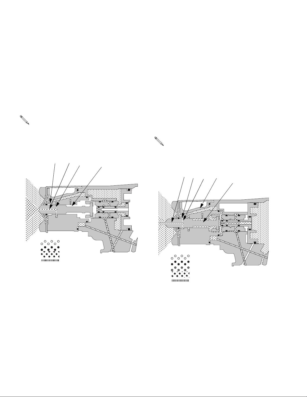
Theory of Operation
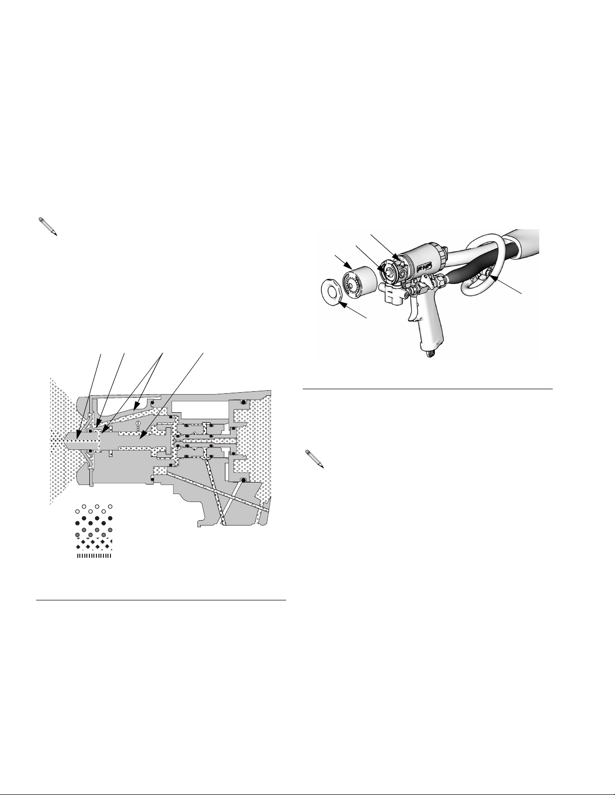
Gun Triggered (Fluid Spraying)
Mix chamber (14) moves back, shutting off
purge air flow. Impingement ports (IP) align
with fluid ports of side seals (42, 43), allowing
fluid to flow through mix chamber nozzle (N).
Flow paths are not shown to scale, for
clarity.
CSL is dosed into purge air.
ACIPN
14
Gun Detriggered (Air Purging)
Mix chamber (14) moves forward, shutting off
fluid flow. Impingement ports (IP) open to air
chamber (AC), allowing purge air to flow
through mix chamber nozzle (N).
See Shutdown (page 16) for use of grease fitting (G).
Flow paths are not shown to scale, for
clarity.
CSL is dosed into purge air.
N
IP
AC
AC
14
!IR
#3,
&LUID
'REASE
TI12123a_1
34 312666R
!IR
#3,
#3,!IR
&LUID
'REASE
TI12124a
Page 35
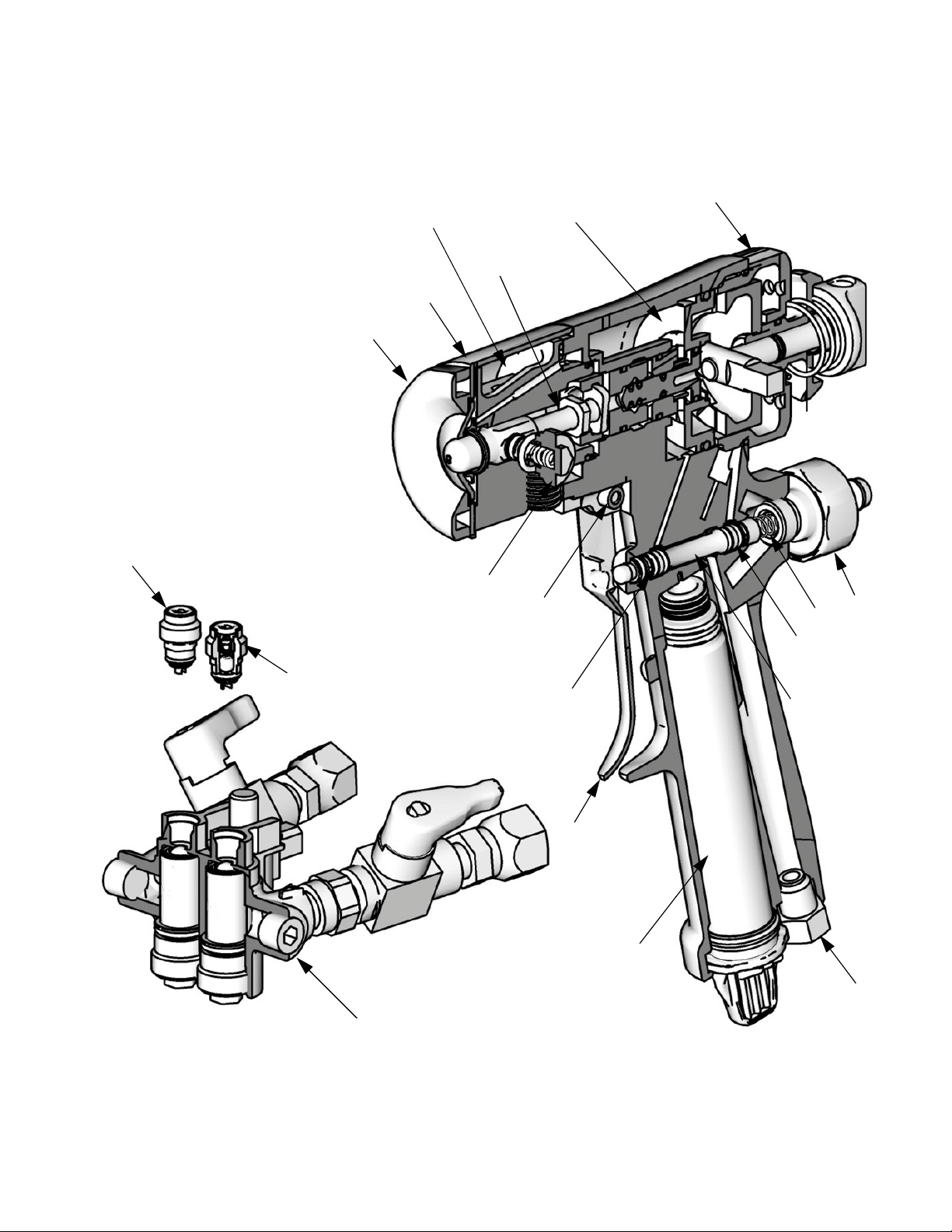
Cutaway View
2 (Fluid Housing Assy.; see page 44)
Theory of Operation
3
4 (Piston Assy.; see page 44)
14
19
20
45
44
42
6
15
15
5
23
17
13
16
9
1 (Hose Manifold Assy.; see page 48)
TI12091a
312666R 35
Page 36

Repair
Repair
Tools Required
Tools required to complete gun repair procedures:
• adjustable wrench
• flat head screwdriver (included)
• 5/16 hex nut driver (included)
Lubrication
See page 55 to order lubricant. Liberally lubricate all o-rings, seals, and threads.
Do not lubricate o-ring, seals, and threads
on ClearShot Liquid cartridge.
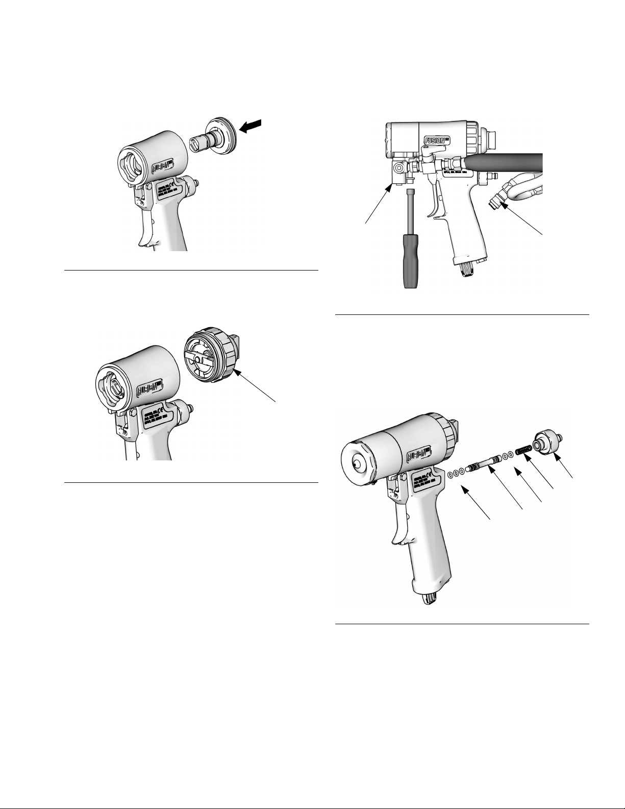
Remove Front End
4. Unscrew and remove front cover retainer
(C).
5. Remove front cover (U).
U
C
FIG. 43
6. Turn fluid housing (F) 1/4 turn counterclockwise to disengage slots. Remove fluid
housing.
2b
TI12092a
Proper attachment of front end is critical. Do
not operate gun if front end is loose or not
snug against handle.
1. Follow Pressure Relief Procedure, page
page 17.
2. Flush Gun, page 26.
CAUTION
If front cover retainer (C) and front cover (U)
are stuck due to material buildup, do not
force it by turning entire front end. Soak front
of gun in solvent to soften cured material and
free front cover and front cover retainer.
3. Use hex nut driver to remove fluid manifold
(M).
F
TI12093a
FIG. 44
7. Inspect fluid housing o-rings for wear or
damage. Replace if necessary.
36 312666R
Page 37

Repair
Attach Front End
Proper attachment of front end is critical. Do
not operate gun if front end is loose or not
snug against handle.
1. Engage piston safety lock, page 12.
TI11326a
F
IG
. 45
4. Turn fluid housing 1/4 turn clockwise to
engage slots.
TI12094a
FIG. 47
5. Replace front cover (U).
6. Screw on front cover retainer (C).
F
U
2b
2. Liberally lubricate o-rings (2c, 2d) and reassemble on fluid housing. Insert keyed end
of mix chamber (14) in socket of piston
assembly (4).
2d
2c
14
IG
. 46
F
4
TI12129a
3. Push fluid housing (F) flush to handle.
C
TI12092a
IG
. 48
F
312666R 37
Page 38

Repair
Mix Chamber and Side Seal Assemblies
See Models/Mix Chamber Selection Guide,
page 4, for available mix chamber sizes.
1. Follow Pressure Relief Procedure, page
17.
2. Remove fluid manifold (M). Leave air connected.
M
5. Remove Front End, page 36.
CAUTION
To prevent cross-contamination of side seal
assemblies, do not interchange A component and B component parts. The A component assembly is marked with an A.
6. Use hex nut driver to remove side seal
assemblies (42, 43).
2a
B
43
FIG. 51
F
42
A
TI12096b
TI12095a
FIG. 49
3. Flush gun to remove residual A and B components. See Flush Gun, page 26. Follow
Pressure Relief Procedure, page 17.
4. Disconnect air (D).
D
TI12086a
FIG. 50
7. Push on front of mix chamber (14) to
loosen. Pull mix chamber out rear of fluid
housing (F). Inspect for damage and Clean
Impingement Ports, page 29.
CAUTION
To prevent cross-contamination of the gun’s
wetted parts, mix chamber is marked with an
A and a notch on back edge. Be sure the A
side of mix chamber is on the A side of gun.
38 312666R
Page 39
Repair
8. Apply thin coat of lubricant to mix chamber
(14). Install mix chamber. Etched A and
notch must be on same side as A on fluid
housing. Mix chamber is keyed to fit in fluid
housing.
14
B
A
TI12097b
IG
. 52
F
CAUTION
To prevent cross-contamination of side seal
assemblies, do not interchange A component and B component parts. The A component assembly is marked with an A.
11.Line up tabs on seal (42c) and seal housing
(42a); insert seal into housing. Push down
on seal and turn to lock in place.
Line up tabs
42d
42c
42b
42e
{
42a
TI12098b
FIG. 53
9. Push down on seal housing (42a) and turn
so side seal detents unlock and remove.
10.Carefully inspect side seal assembly
o-rings and surfaces. Replace worn or
damaged parts. Liberally lubricate o-rings
(42d, 42e) and reassemble.
312666R 39
Page 40
Repair
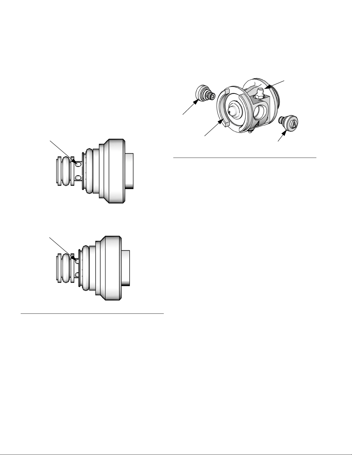
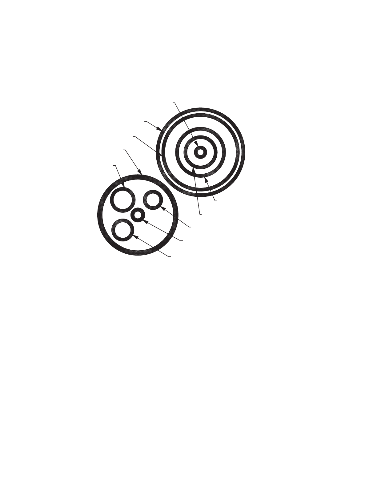
12.Check for proper spring (42b) operation,
and that the seal (42c) rotates slightly in the
seal housing (42a) detents.
When the seal is installed correctly the
spring will be flexible and all four cross
holes of the seal will be completely visible.
See FIG. 54 for an example of the correct
and incorrect seal installation.
Correct Seal Installation
Cross Hole
TI12639a
Incorrect Seal Installation
Cross Hole
13.Liberally lubricate and reinstall side seal
assemblies (42, 43). Use hex nut driver to
tighten.
B
2a
A
43
F
FIG. 55
14.Attach Front End, page 37.
15.Connect air, and trigger the gun a few
times to check for leaks. If purge air leaks
from mix chamber nozzle when gun is triggered, inspect mix chamber and side seals.
Correct the problem before attaching fluid
manifold.
16.Attach fluid manifold (F). Connect air.
Return gun to service.
42
TI12096b
TI12640a
IG
. 54
F
40 312666R
Page 41
Repair
Check Valves
1. Follow Pressure Relief Procedure, page
17.
2. Remove fluid manifold (M). Leave air connected. Clean Fluid Manifold, page 27.
M
TI12095a
FIG. 56
3. Flush gun to remove residual A and B components. See Flush Gun, page 26. Follow
Pressure Relief Procedure, page 17.
4. Disconnect air (D).
D
5. Use hex nut driver to remove check valves
(44, 45).
6. Disassemble check valves using a flat
head screwdriver.
44e
FIG. 58
.
CAUTION
Damaged check valve o-rings (44e, 44f) may
result in external leakage. Replace o-rings if
they are damaged.
7. Clean and inspect all parts. Thoroughly
inspect o-rings (44e, 44f). Press on ball
(44b) to test check valve for proper movement and spring action. Replace individual
check valve parts as needed.
F
TI12086a
IG
. 57
F
45
CAUTION
44e
44d
44c
44b
44a
44f
To prevent cross-contamination of the check
valves, do not interchange A component and
B component parts. The A component check
FIG. 59
TI12099a
valve is marked with an A.
312666R 41
Page 42

Repair
8. Liberally lubricate o-rings (44e, 44f) and
carefully reinstall in fluid housing (F). Use
hex nut driver to tighten.
9. Attach fluid manifold (M). Connect air (D).
Return gun to service.
Piston
1. Follow Pressure Relief Procedure, page
17
2. Disconnect air (D) and remove fluid manifold (M).
5. Push piston shaft to remove piston (4b).
Inspect piston o-ring (4c) and shaft o-rings
(4a).
4b
4c
4a
TI12101a
FIG. 62
6. Remove dosing piston.
a. Use supplied screw driver to remove
spiral retaining ring (4g).
M
D
TI11330a
FIG. 60
3. Remove Front End, page 36.
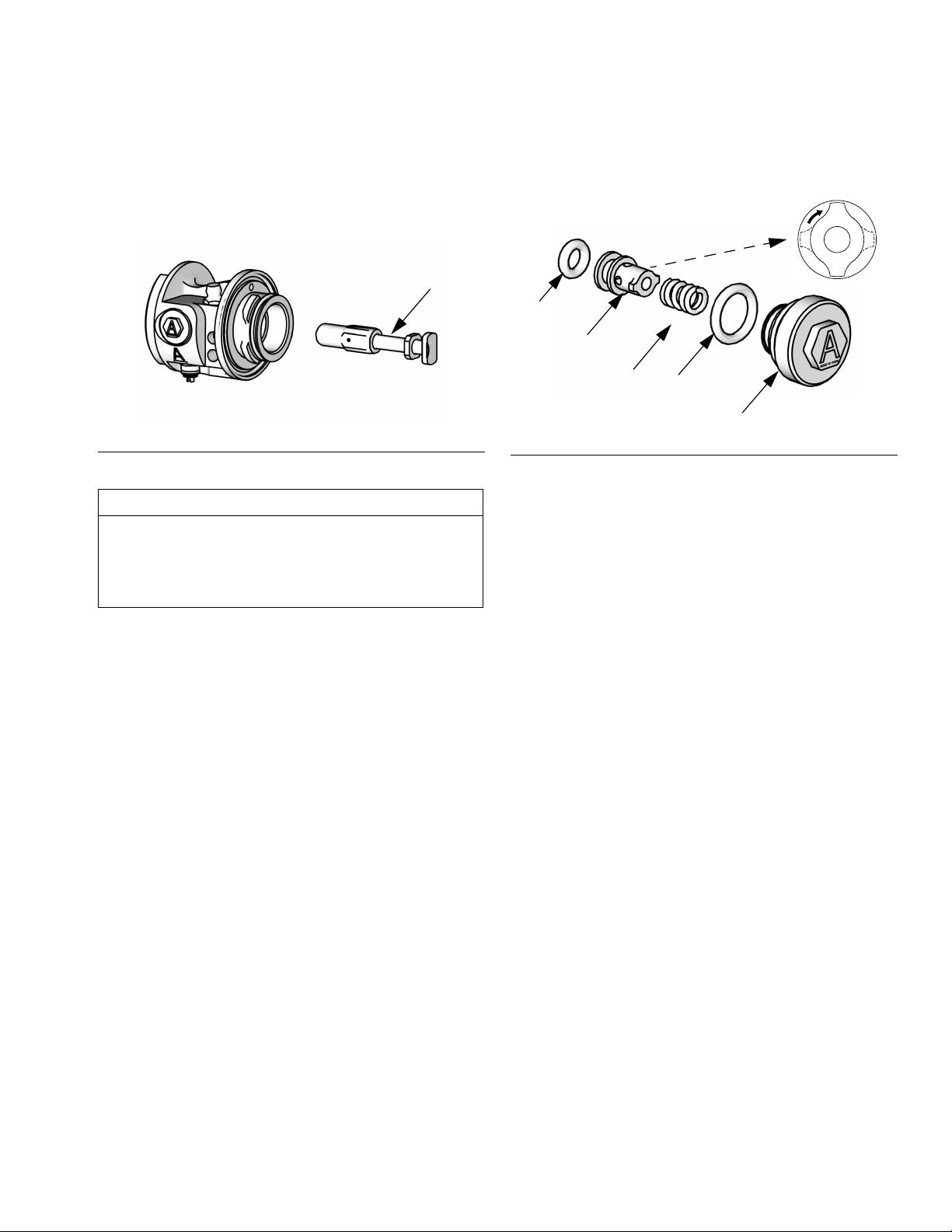
4. Unscrew variable flow adjustment knob (X)
and inspect o-ring (3a).
X
3a
b. Use screw driver to push dosing piston
(4e) out back of piston (4b) through
access hole on front side.
7. Clean and inspect o-rings on dosing piston
(4e). Clean dosing bore in piston (4b) with
a nylon brush and compatible solvent.
8. Lubricate dosing piston (4e) o-rings with
ClearShot Liquid prior to reassembly.
9. Liberally lubricate piston o-ring (4c) and
lightly lubricate shaft o-rings (4a).
10.Reinstall retaining ring (4g). Press it into
groove of dosing piston (4e).
TI12100a
FIG. 61
42 312666R
Page 43
Repair
11.Reinstall piston. Shaft is keyed for proper
assembly. Push firmly to seat piston.
TI12102a
FIG. 63
12. Install variable flow adjustment knob (X).
2. Disconnect air (D) and remove fluid manifold (M).
M
D
TI11330a
FIG. 65
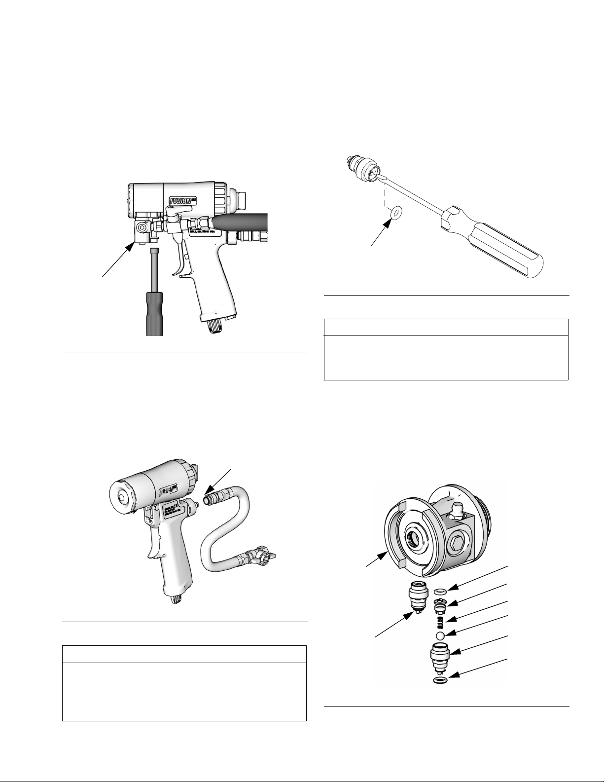
3. Unscrew air valve plug (13) and remove
spring (16). Using a small diameter tool,
push spool (17) out from front. Inspect all
five o-rings (15).
X
TI12100a
FIG. 64
13. Attach Front End, page 37.
14. Attach fluid manifold (M).
15. Install ClearShot Liquid cartridge. See
ClearShot Liquid Cartridge Installation/Removal , page 23.
16.Connect air. Return gun to service.
Air Valve
1. Follow Pressure Relief Procedure, page
17
}
}
15
17
15
TI12103a
FIG. 66
4. Liberally lubricate o-rings and reassemble.
Torque plug (13) to 25-135 in-lb (14-15
N•m).
5. Attach fluid manifold (M). Connect air (D).
Return gun to service.
13
16
312666R 43
Page 44

Parts
Parts
Seal Assembly (42) Detail
42d
42c
42b
42e
42a
43
2f
4a
TI12098b
1
1
2a
4
1
4d, 4e, 4f
4b
4c
14
1
Apply light coating of
Fusion grease (31).
2
Apply sealant to threads.
1
3
3a
1
4g
1
1
3
4
17, 15
Torque to 20-30 in-lb (2.3-3.4 N•m).
Torque to 35-40 in-lb (4.0-4.5 N•m).
13
1
16
1
20
1
2b
42
45
19
44
1 (see page 48 for details)
Variable-Flow Adjuster (3) Detail
2d
TI12104a
2c
32
1
34
1
7
2
8
5
1
6
3
11
1
4
9
23
33
Check Valve (44) Detail
44e
2
44d
44c
44b
3c
44a
3b
44f
3a
r_256366_312666
44 312666R
TI12105a
Page 45

Parts
Parts
Ref. Part Description Qty.
1 256466 MANIFOLD, hose, assy. 1
1a MANIFOLD 1
1b✓ 256462 KIT, valve, check, a side;
includes 1c and 256469
(o-ring)
1c† 256462 KIT, valve, check, b side;
includes 1b and 256469
(o-ring)
1d 15B221 BOLT; 5/16-24 3
1e 100139 PLUG, pipe 1
1f 117634 SWIVEL, union; #6 JIC 1
1g 117635 SWIVEL, union 1
1h‡ 256460 VALVE, ball, resin 1
1j‡ 256459 VALVE, ball, iso 1
1k 15U395 ADAPTER, male x female;
1/8 npt
2 256457 HOUSING, fluid, assy;
includes 2a-2f and 42-45
2a 100846 FITTING, lubrication 1
2b✓ 248648 O-RING (pack of 6) 1
2c✓ 256773 O-RING (pack of 6) 1
2d✓ 248132 O-RING (pack of 6) 1
2f HOUSING 1
3 256456 ADJUSTER, variable-flow 1
3a✓ 256774 O-RING (pack of 6) 1
3b 257426 O-RING (pack of 6) 1
3c 257425 O-RING (pack of 6) 1
4 256454 PISTON, assy. 1
4a✓ 256772 O-RING (pack of 6) 2
4b PISTON 1
4c✓ 256775 O-RING (pack of 6) 1
4d O-RING 3
4e 257424 PISTON, dosing, assy;
includes 4d and 4f
4f 257426 O-RING (pack of 6) 1
4g 121642 RING, retaining, internal
spiral
Ref. Part Description Qty.
5 15B209 TRIGGER 1
6 192272 PIN, pivot 1
7 203953 SCREW; 10-24 x 3/8 in.
1
8 15C480 WASHER, wave 1
(10 mm)
9 121540 PLUG, breather 1
11 256458 HANDLE, kit; includes ref. 12 1
1
13 15T897 PLUG, air valve 1
14❖ CHAMBER, mix 1
15 O-RING 5
16 117485 SPRING, compression 1
17 256455 VALVE, spool; includes 15 1
19 256414 RETAINER, cover (pack of 5) 1
20 ✖256415 COVER, front, round, tip
(pack of 5)
✠ 256416 COVER, front, flat, tip
2
(pack of 5)
21✠ * TIP, spray 1
1
23★ 256385 KIT, clearshot cartridge
(pack of 25)
25❖ TOOL, cleanout 1
26❖ TOOL, cleanout 1
27❖ TOOL, cleanout, #69
28 117661 PIN, vise 1
29† 117773 LUBRICANT 1
30† 117792 GUN, grease 1
31† 118665 GREASE, Fusion; 4 oz 1
32 117510 COUPLER, line, air;1/4 npt 1
33 15B565 VALVE, ball 1
34 15B772 HOSE, air; 18 in. 1
35 112307 ELBOW, street 2
36 117642 NUT DRIVER 1
37 118575 SCREW DRIVER, 1/8 blade 1
38
▲
1
39
172479 TAG, instruction 1
▲
222385 TAG, warning 1
1
1
1
1
1
312666R 45
Page 46

Parts
Ref. Part Description Qty.
40 256641 MANIFOLD, flush; includes
1d, 49, and 50.
41 256642 KIT, inlet cap; includes 1d 1
42 256463 KIT, seal, a side, assy;
includes 42a-42e and 43
42a HOUSING, seal, side 1
42b 256923 SPRING, compression
(pack of 10)
42c❄ 256464 SEAL, side; includes 42d 1
42d
42e
43† 256463 KIT, seal, b side, assy;
43c❄ 256464 SEAL, side; includes 43d 1
43d
43e
44
44e
44f
45
45e
45f
46✠ 256567 RETAINER, tip 1
47✠✿ 246360 O-RING; PTFE (pack of 3) 1
49 100721 PLUG, pipe 1
50 117509 FITTING, air line; 1/4 npt 1
256467 O-RING (pack of 6) 1
✓
256468 O-RING (pack of 6) 1
✓
includes 42 and 43a-43e
43a HOUSING, seal, side 1
43b 256923 SPRING, compression 1
256467 O-RING (pack of 6) 1
✓
256468 O-RING (pack of 6) 1
✓
257422 KIT, valve, check, a side;
◆
includes 44a-44f
44a 257427 HOUSING, check valve, a
side (pack of 10)
44b 257420 BALL; carbide (pack of 10) 1
44c 257419 SPRING, compression
(pack of 10)
44d 257421 RETAINER, ball (pack of 10) 1
246354 O-RING (pack of 6) 1
✓
256771 O-RING (pack of 6) 1
✓
257423 KIT, valve, check, b side;
◆
†
includes 45a-45f
45a 257428 HOUSING, check valve, b
side (pack of 10)
45b 257420 BALL; carbide (pack of 10) 1
45c 257419 SPRING, compression
(pack of 10)
45d 257421 RETAINER, ball (pack of 10) 1
246354 O-RING (pack of 6) 1
✓
256771 O-RING (pack of 6) 1
✓
▲
Replacement Danger and Warning labels,
1
tags, and cards are available at no cost.
† Not shown.
1
✖
Wide and round pattern models only.
✠
Flat pattern models only.
1
❖
See tables on page 47 for kit number.
✓
Also included in o-ring repair kit(s); see
page 51.
1
★
ClearShot Liquid cartridges also available in
packages of 50 and 100. See Accessories,
page 55.
❄
Side seals also available in packages of 2
and 20. See Accessories, page 55.
✿
1
Also included in Kits FL0000, FL0101,
FL0202, and FL2020.
1
◆
Parts included in kit 256461.
*See Flat Tip Kits, page 50, for part number.
1
‡ Replacement handles are available in Kit
24W375.
1
1
1
46 312666R
Page 47

Parts
Wide and Round Pattern Models Varying
Parts Table
Reference Number
Model 14 25 26 27
CS00WD Order Kit WD0000
CS01WD Order Kit WD0101
CS02WD Order Kit WD0202
CS03WD Order Kit WD0303
CS22WD Order Kit WD2222
CS01RD Order Kit RD0101
CS02RD Order Kit RD0202
CS03RD Order Kit RD0303
CS20RD Order Kit RD2020
CS00RD Order Kit RD0000
Flat Pattern Models Varying Parts Table
Reference Number
Model 14 25 26 27
CS00F1 Order Kit FL0000
CS00F2 Order Kit FL0000
CS00F3 Order Kit FL0000
CS00F4 Order Kit FL0000
CS00F5 Order Kit FL0000
CS00F6 Order Kit FL0000
CS01F1 Order Kit FL0101
CS01F2 Order Kit FL0101
CS01F3 Order Kit FL0101
CS01F4 Order Kit FL0101
CS01F5 Order Kit FL0101
CS01F6 Order Kit FL0101
CS02F1 Order Kit FL0202
CS02F2 Order Kit FL0202
CS02F3 Order Kit FL0202
CS02F4 Order Kit FL0202
CS02F5 Order Kit FL0202
CS02F6 Order Kit FL0202
CS20F1 Order Kit FL2020
CS20F2 Order Kit FL2020
Convert Round Pattern to Flat Pattern
To convert a round pattern gun to a flat pattern
gun, order the following parts.
Ref. Part Description Qty.
14 FLxxxx CHAMBER, mix; see Flat
Pattern Mix Chamber Kits,
page 50
20 256416 COVER, front, flat, tip
(pack of 5)
21 FTxxxx TIP, spray; see Flat Tip Part
Reference Guide, page 50
46 256567 RETAINER, tip 1
Convert Flat Pattern to Round Pattern
To convert a flat pattern gun to a round pattern
gun, order the following parts.
Ref. Part Description Qty.
14 RDxxxx CHAMBER, mix; see Round
Pattern Mix Chamber Kits,
page 49
WDxxxx CHAMBER, mix; see Wide
Pattern Mix Chamber Kits,
page 49
20 256415 COVER, front, round, tip
(pack of 5)
1
1
1
1
1
312666R 47
Page 48
Parts
Detail Views
Flat Pattern Detail
Supplied Tools
36
25-27
37
46
21
47
14
TI12106a
TI3870a
2-Hose Fluid Manifold (1) Detail
‡
1h
1a
1
1b
1e
1d
Flush Manifold Detail
49
3
1k
1f
3
1g
3
3
‡
1j
3
TI12107a
Fluid Inlet Cover Detail
41
1d
TI12197a
40
1d
1
Apply lubricant to seals.
3
Apply sealant to threads.
50
TI12108a
3
48 312666R
Page 49

Mix Chamber Kits
Round Pattern Mix Chamber
Kits
Parts
Mix
Chamber
Kit
(includes
drill bits)
RD2020 5 (127) 0.042 #58
RD0000 8 (203) 0.052 #55
RD0101 11 (279) 0.060 #53
RD0202 12 (305) 0.070 #50
RD0303 14 (356) 0.086 #44
Pattern
Diameter at 24
in. (609.6 mm)
to target in
(mm)
Nozzle
Orifice
Size
Nozzle
Drill Bit
Size,
in. (mm)
(1.00)
(1.30)
(1.50)
(1.75)
(2.15)
Impinge-
ment Port
Impingement Port
Size
0.020 #76 (0.50) 0.060 #53 (1.50)
0.029 #69 (0.70) 0.060 #53 (1.50)
0.042 #58 (1.00) N/A N/A
0.052 #55 (1.30) N/A N/A
0.060 #53 (1.50) N/A N/A
Drill Bit
Size, in.
(mm)
Counterbore Size
Counterbore Drill Bit
Size,
in. (mm)
Wide Pattern Mix Chamber Kits
Kits include mix chamber and cleanout drills. To spray larger diameter patterns than standard mix
chambers.
Pattern Diameter at
24 in. (609.6 mm)
Kit Part
WD2222 8 (203.2) N/A 0.047 (1.20) #74, 0.022 (0.56)
WD0000 15 (381.0) Ref. RD0000 1/16, 0.062 (1.59) #70, 0.028 (0.71)
WD0101 16 (406.4) Ref. RD0101 #50, 0.070 (1.78) #61, 0.039 (0.99)
WD0202 18 (457.2) Ref. RD0202 0.085 (2.15) #56, 0.046 (1.17)
WD0303 18 (457.2) Ref. RD0303 #42, 0.089 (2.26) 1.45 mm, 0.057 (1.45)
312666R 49
to target in (mm)
Equivalent flow to
mix chamber size
Nozzle Drill Bit Size
in (mm) *
Impingement Drill Bit Size
in. (mm) *
Page 50

Parts
Flat Pattern Mix Chamber Kits
Mix
Chamber Kit
(includes
drill bits and
o-ring)
FL2020 246360 0.094 3/32
FL0000 246360 0.094 3/32
FL0101 246360 0.094 3/32
FL0202 246360 0.094 3/32
Ref.
47†,
O-ring
Nozzle
Orifice
Size
Nozzle
Drill Bit
Size,
in. (mm)
(2.35)
(2.35)
(2.35)
(2.35)
Impingement Port
Size
0.020 #76 (0.50) 0.060 #53 (1.50)
0.029 #69 (0.70) 0.060 #53 (1.50)
0.042 #58 (1.00) N/A N/A
0.052 #55 (1.30) N/A N/A
Impingement Port
Drill Bit
Size, in.
(mm)
† Available only in flat mix chamber kits or in 246360 multi-pack kit.
Mix Chamber Part Reference
Flat Tip Kits
Guide
Sample part RD0101:
Flat
Pattern
Model
Ref. 21,
Spray
Tip Pattern Size, in. (mm)
Counterbore Size
Counterbore Drill
Bit Size,
in. (mm)
RD 01 01
RD= round pattern
FL= flat pattern
WD = wide pattern
A orifice
size (0.042
in.)
B orifice
size (0.042
in.)
CSxxF1 FT0424 low flow, 8-10 (203-254)
CSxxF2 FT0438 medium flow, 8-10 (203-254)
CSxxF3 FT0624 low flow, 12-14 (305-356)
CSxxF4 FT0638 medium flow, 12-14
(305-356)
CSxxF5 FT0838 medium flow, 16-18
(406-457)
CSxxF6 FT0848 high flow, 16-18 (406-457)
Flat Tip Part Reference Guide
Sample part FT0848:
FT 08 48
FT=Flat tip x2=pattern
length
(8x2=16 in.)
Equivalent orifice
diameter size
(.048 in.)
50 312666R
Page 51

O-ring Repair Kits
The following table indicates the specific o-ring(s) reference number and quantity included in
each o-ring kit.
Reference Number
Parts
Kit
256490
Complete Kit
256467
Side Seal
256468
Side Seal
Housing
256640
Fluid Head
Check Valves
256471
Fluid Head
256470
Air Piston
256472
Back Cap
256469
Hose
Manifold
Check Valves
1b 2b 2c 2d 3a 4a 4c 42d,
43d
21111212222
6
111
21
1
6
42e,
43e
6
44e,
45e
66
44f,
45f
Bulk O-ring Kits
The following table indicates the specific o-ring(s) reference number and corresponding kit number. Each kit includes a quantity of six o-rings.
Reference Number
1b 2b 2c 2d 3a 4a 4c 42d,
43d
256469 248648 256773 248132 256774 256772 256775 *256467 256468 246354 256771
Kit
* Includes installation tools and side seal springs.
312666R 51
42e,
43e
44e,
45e
44f,
45f
Page 52
Parts
Complete O-ring Kit Placement
Guide
Each o-ring in kit 256490 is labeled by the reference number. See the table entry for 256490 in
O-ring Repair Kits on page 51 for the quantity of each.
42d, 44e
43d, 45e
3a
2d
4c
1b
2c
Check Valve Filter Screen Kits
Kits include 10 filter screens.
The 80 mesh filter screen is standard with gun.
Part Description
246357 40 mesh (0.015 in., 375 micron)
246358 60 mesh (0.010 in., 238 micron)
246359 80 mesh (0.007 in., 175 micron)
4a
42e, 43e
44f, 45f
2b
52 312666R
Page 53

Drill Bit Kits
For cleaning gun ports and orifices. Illustrations are actual size for comparison.
Not all sizes are used with every gun
model.
Parts
Kit Part
249115 6 1/8 0.125 3.18
246623 3 #32 0.116 2.90
246810 3 7/64 0.109 2.77
246813 3 #39 0.099 2.51
246624 3 3/32 0.094 2.39
246812 3 #43 0.089 2.26
246625 3 #44 0.086 2.18
248639 6 2.15 mm 0.085 2.15
249114 6 #45 0.082 2.08
246811 3 2 mm 0.079 2.00
Qty in
Kit
Drill Bit Size
nominal in. mm
Illustration
246626 6 #50 0.070 1.78
249113 6 #52 0.64 1.63
248893 6 1/16 0.062 1.59
246627 6 #53 0.060 1.52
249112 6 1.45 mm 0.057 1.45
246809 6 #54 0.055 1.40
246628 6 #55 0.052 1.32
249764 6 1.20 mm 0.047 1.20
246814 6 #56 0.046 1.18
312666R 53
Page 54

Parts
Kit Part
246629 6 #58 0.042 1.07
246808 6 #60 0.040 1.02
248640 6 #61 0.039 0.99
248618 6 #63 0.037 0.94
248891 6 #66 0.033 0.84
246807 6 #67 0.032 0.81
246630 6 #69 0.029 0.74
248892 6 #70 0.028 0.71
246815 6 #73 0.024 0.61
276984 6 #74 0.023 0.57
Qty in
Kit
Drill Bit Size
nominal in. mm
Illustration
246631 6 #76 0.020 0.51
246816 6 #77 0.018 0.46
246817 6 #81 0.013 0.33
ClearShot Handle Cleanout Drill Kit
256526
Kit includes all 7 drill bits of extra length
needed to clean out all air passages in the
Fusion CS gun handle and fluid housing. See
Clean Passages, page 29.
54 312666R
Page 55

Accessories
Accessories
Stainless Steel Side Seal Kit
Kit 256464 includes 2 stainless steel side
seals and 2 o-rings.
Polycarballoy Side Seal Kits
Kits include a packing o-ring for each polycarballoy side seal. The optional high wear,
non-metallic polycarballoy seals are for alternate fluids.
Kit Description
256465
256489
SEAL KIT,
Polycarballoy
SEAL KIT,
Polycarballoy
Number of
Seals Per Kit
2
20
Grease Cartridge for Gun Shutdown
248280 Cartridge, 3 oz [10]
Specially formulated low viscosity grease flows
easily through gun passages, to prevent
two-component curing and keep fluid passages clean.
Flushing Manifold
256641 Manifold Block
See page 48.
Fluid Inlet Cover
Kit 256642; includes 15R910 and 15B221. See
page 48.
Flat Pattern Stud Wall Kits
Use to spray wall insulation foam into stud
walls with a single pass.
Kit Description
256569 Includes TP100
256570 Includes FTM979
Gun Cover
244914 Covers
Keeps gun clean while spraying. Pack of 10.
Lubricant for Gun Rebuild
248279, 4 oz (113 gram) [10]
High adhesion, water resistant, lithium-based
lubricant. MSDS sheet available at
www.graco.com.
Gun Cleaning Kit
15D546
Kit includes 11 tools and brushes to clean the
gun.
ClearShot Liquid Cartridges
See MSD060.
Kit Description
256385 Package of 25 cartridges
256386 Package of 50 cartridges
256387 Package of 100 cartridges
312666R 55
Page 56
Accessories
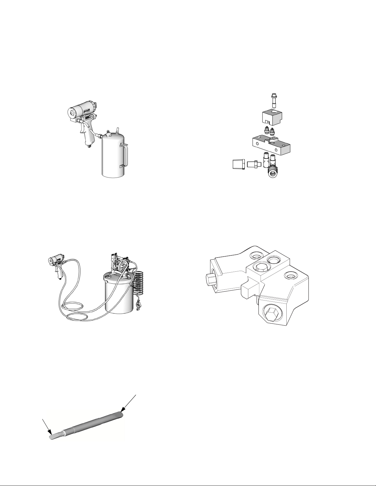
Solvent Flush Canister Kit
256510, 1 qt (0.95 liter) Solvent Cup
Includes flushing manifold to flush gun with
solvent. Portable for remote flushing. See
manual 309963.
TI12110a
Solvent Flush Pail Kit
248229 5.0 gal. (19 liter) Pail
Includes flush manifold with individual A and B
shutoff valves, and air regulator. See manual
309963.
Circulation Manifold
256566
Attach to gun fluid manifold to enable preheating of hose. See manual 313058.
TI12109a
Fusion AP Manifold Adapter
258996
Allows Fusion CS gun to fit onto existing
Fusion manifold.
TI12111a
ti18633a
Tip Cleanout Tool
15D234
Designed to fit CeramTip internal dome and
flat tip slits.
End for
Mechanical
End for Air
Purge Tips
56 312666R
Purge Tips
TI4244a
Page 57

Technical Data
Category Data
Maximum Fluid Working Pressure 3500 psi (24.5 MPa, 245 bar)
Minimum Air Inlet Pressure 80 psi (0.56 MPa, 5.6 bar)
Maximum Air Inlet Pressure 130 psi (0.9 MPa, 9 bar)
Air Flow Range See chart below
Maximum Fluid Temperature 200° F (94° C)
Air Inlet Size 1/4 npt Quick Disconnect Nipple
A Component (ISO) Inlet Size -5 JIC; 1/2-20 UNF
B Component (Resin) Inlet Size -6 JIC; 9/16-18 UNF
Sound Pressure
Sound Power, measured per ISO 9416-2
Dimensions 7.5 x 8.1 x 3.3 in. (191 x 206 x 84 mm)
Weight 2.6 lbs (1.18 kg)
Wetted Parts
75.27 dB(A), using RD0202 at 100 psi
(0.7 MPa, 7 bar)
73.45 dB(A), using RD0202 at 100 psi
(0.7 MPa, 7 bar)
Aluminum, stainless steel, carbon steel, carbide, chemically resistant o-rings
Technical Data
All other brand names or marks are used for identification purposes and are trademarks of their
respective owners.
Air Flow Data
Air Pressure (detriggered)
psi (MPa, bar)
80 (0.56, 5.6)
100 (0.7, 7)
130 (0.9, 9)
Air Flow in scfm (m3/min)
for all mix chambers
2.1
(0.059)
3.1
(0.088)
5.2
(0.147)
312666R 57
Page 58

Graco Standard Warranty
Graco warrants all equipment referenced in this document which is manufactured by Graco and bearing its name to be free from
defects in material and workmanship on the date of sale to the original purchaser for use. With the exception of any special,
extended, or limited warranty published by Graco, Graco will, for a period of twelve months from the date of sale, repair or replace
any part of the equipment determined by Graco to be defective. This warranty applies only when the equipment is installed,
operated and maintained in accordance with Graco’s written recommendations.
This warranty does not cover, and Graco shall not be liable for general wear and tear, or any malfunction, damage or wear caused
by faulty installation, misapplication, abrasion, corrosion, inadequate or improper maintenance, negligence, accident, tampering,
or substitution of non-Graco component parts. Nor shall Graco be liable for malfunction, damage or wear caused by the
incompatibility of Graco equipment with structures, accessories, equipment or materials not supplied by Graco, or the improper
design, manufacture, installation, operation or maintenance of structures, accessories, equipment or materials not supplied by
Graco.
This warranty is conditioned upon the prepaid return of the equipment claimed to be defective to an authorized Graco distributor
for verification of the claimed defect. If the claimed defect is verified, Graco will repair or replace free of charge any defective parts.
The equipment will be returned to the original purchaser transportation prepaid. If inspection of the equipment does not disclose
any defect in material or workmanship, repairs will be made at a reasonable charge, which charges may include the costs of parts,
labor, and transportation.
THIS WARRANTY IS EXCLUSIVE, AND IS IN LIEU OF ANY OTHER WARRANTIES, EXPRESS OR IMPLIED, INCLUDING
BUT NOT LIMITED TO WARRANTY OF MERCHANTABILITY OR WARRANTY OF FITNESS FOR A PARTICULAR
PURPOSE.
Graco’s sole obligation and buyer’s sole remedy for any breach of warranty shall be as set forth above. The buyer agrees that no
other remedy (including, but not limited to, incidental or consequential damages for lost profits, lost sales, injury to person or
property, or any other incidental or consequential loss) shall be available. Any action for breach of warranty must be brought within
two (2) years of the date of sale.
GRACO MAKES NO WARRANTY, AND DISCLAIMS ALL IMPLIED WARRANTIES OF MERCHANTABILITY AND FITNESS
FOR A PARTICULAR PURPOSE, IN CONNECTION WITH ACCESSORIES, EQUIPMENT, MATERIALS OR COMPONENTS
SOLD BUT NOT MANUFACTURED BY GRACO. These items sold, but not manufactured by Graco (such as electric motors,
switches, hose, etc.), are subject to the warranty, if any, of their manufacturer. Graco will provide purchaser with reasonable
assistance in making any claim for breach of these warranties.
In no event will Graco be liable for indirect, incidental, special or consequential damages resulting from Graco supplying
equipment hereunder, or the furnishing, performance, or use of any products or other goods sold hereto, whether due to a breach
of contract, breach of warranty, the negligence of Graco, or otherwise.
FOR GRACO CANADA CUSTOMERS
The Parties acknowledge that they have required that the present document, as well as all documents, notices and legal
proceedings entered into, given or instituted pursuant hereto or relating directly or indirectly hereto, be drawn up in English. Les
parties reconnaissent avoir convenu que la rédaction du présente document sera en Anglais, ainsi que tous documents, avis et
procédures judiciaires exécutés, donnés ou intentés, à la suite de ou en rapport, directement ou indirectement, avec les
procédures concernées.
Graco Information
For the latest information about Graco products, visit www.graco.com.
TO PLACE AN ORDER, contact your Graco distributor or call to identify the nearest distributor.
Phone: 612-623-6921 or Toll Free: 1-800-328-0211 Fax: 612-378-3505
All written and visual data contained in this document reflects the latest product information available at the time of publication.
GRACO INC. AND SUBSIDIARIES • P.O. BOX 1441 • MINNEAPOLIS MN 55440-1441 • USA
Copyright 2008, Graco Inc. All Graco manufacturing locations are registered to ISO 9001.
Graco reserves the right to make changes at any time without notice.
For patent information, see www.graco.com/patents.
Original instructions.
International Offices: Belgium, China, Japan, Korea
This manual contains English. MM 312666
Graco Headquarters: Minneapolis
www.graco.com
Revised January 2015
 Loading...