

Page 1
Instructions - Parts List
®
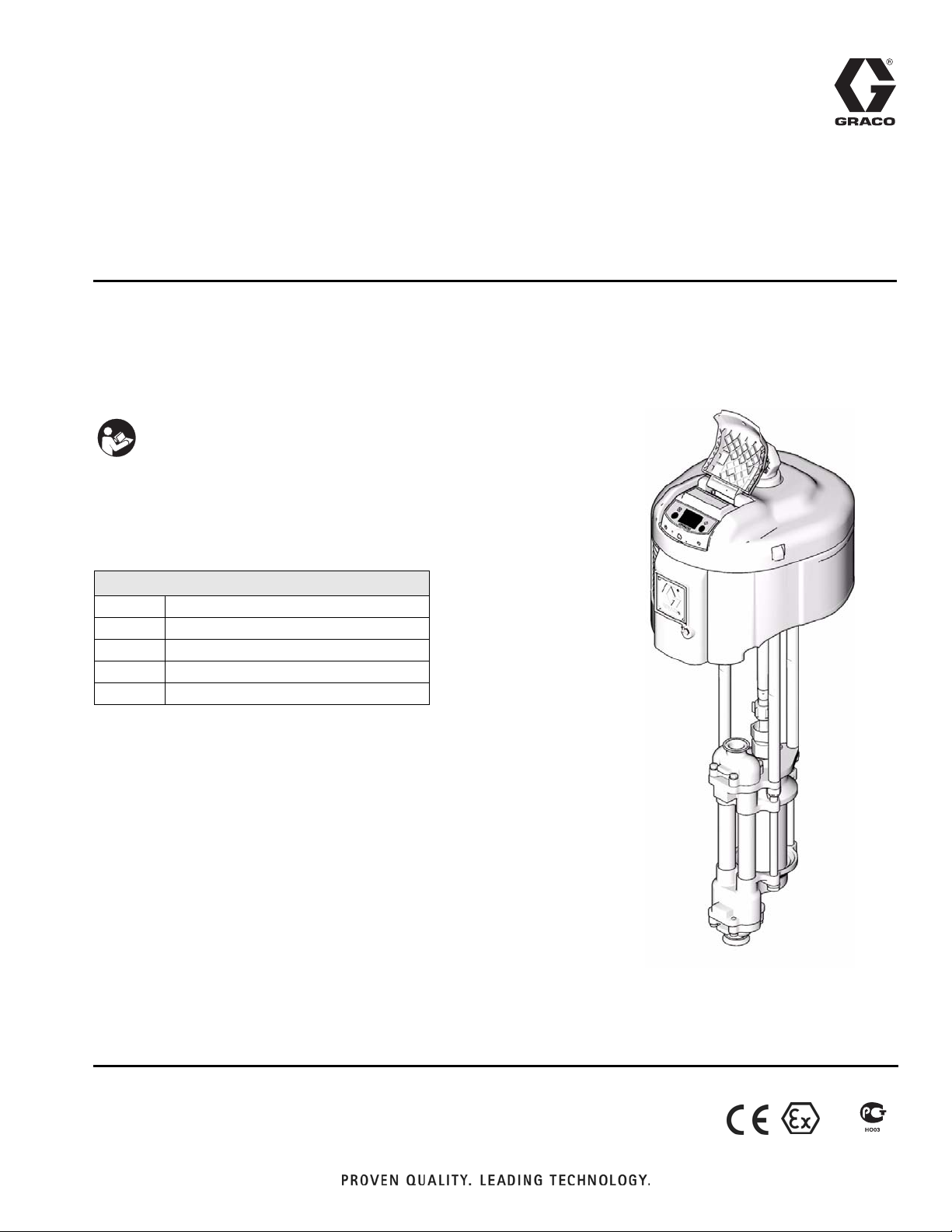
High-Flo
Designed for low pressure, medium volume circulation of finishing materials.
Do not use with caustics, acids, abrasive line strippers, and other similar fluids.
Important Safety Instructions
Read all warnings and instructions in this manual.
Save these instructions.
See page 2 for Table of Conten ts and page 3 for
List of Models.
Pumps
311211L
See page 25 for Maximum Working Pressures.
Related Manuals
Part No. Description
311238 NXT Air Motor manual
308330 Viscount I Plus Hydraulic Motor manual
311690 High-Flo Lower manual
308048 Viscount II Hydraulic Motor manual
Patent Pending
NXT Air-Powered
Pump Shown
TI8354a
II 2 G
Page 2

Contents
Models . . . . . . . . . . . . . . . . . . . . . . . . . . . . . . . . . . . 3
NXT Air-Powered Pumps . . . . . . . . . . . . . . . . . . 3
Viscount I Plus Hydraulic-Powered Pumps . . . . . 3
Viscount II Hydraulic Powered Pumps . . . . . . . . 4
Warnings . . . . . . . . . . . . . . . . . . . . . . . . . . . . . . . . . 5
Installation . . . . . . . . . . . . . . . . . . . . . . . . . . . . . . . . 7
Grounding . . . . . . . . . . . . . . . . . . . . . . . . . . . . . . 7
Accessories . . . . . . . . . . . . . . . . . . . . . . . . . . . . . 8
Air-Powered Pumps . . . . . . . . . . . . . . . . . . . 8
Hydraulic-Powered Pumps . . . . . . . . . . . . . . 8
All Pumps . . . . . . . . . . . . . . . . . . . . . . . . . . . 9
Air-Powered Pumps Typical Installation . . . . . . 10
Hydraulic-Powered Pumps Typical Installation . 11
Operation . . . . . . . . . . . . . . . . . . . . . . . . . . . . . . . . 12
Pressure Relief Procedure . . . . . . . . . . . . . . . . 12
Flush Before Using Equipment . . . . . . . . . . . . . 12
Trigger Lock . . . . . . . . . . . . . . . . . . . . . . . . . . . . 12
Pump Operation . . . . . . . . . . . . . . . . . . . . . . . . 12
Stop the Pump at the Bottom of Its Stroke . . . . 12
Maintenance . . . . . . . . . . . . . . . . . . . . . . . . . . . . . . 13
Preventive Maintenance Schedule . . . . . . . . . . 13
Flushing . . . . . . . . . . . . . . . . . . . . . . . . . . . 13
Air Line Filter . . . . . . . . . . . . . . . . . . . . . . . 13
Hydraulic Power Supply Check . . . . . . . . . . 13
Mix Tank Volume . . . . . . . . . . . . . . . . . . . . . 13
Packing Nut Tightness . . . . . . . . . . . . . . . . 13
Excessive Leaking at Throat . . . . . . . . . . . 13
Troubleshooting . . . . . . . . . . . . . . . . . . . . . . . . . . . 14
Repair . . . . . . . . . . . . . . . . . . . . . . . . . . . . . . . . . . . 15
Disconnect the Lower . . . . . . . . . . . . . . . . . . . . 15
Reconnect the Lower . . . . . . . . . . . . . . . . . . . . . 15
Reassemble the Coupling Rod and Tie Rods
to the Motor . . . . . . . . . . . . . . . . . . . . . . . . . 16
Parts . . . . . . . . . . . . . . . . . . . . . . . . . . . . . . . . . . . . 18
NXT Pumps . . . . . . . . . . . . . . . . . . . . . . . . . . . . 18
Common Parts . . . . . . . . . . . . . . . . . . . . . . 18
Parts That Vary by Model . . . . . . . . . . . . . . 19
Viscount I Plus Pumps . . . . . . . . . . . . . . . . . . . . 21
Common Parts . . . . . . . . . . . . . . . . . . . . . . 21
Parts That Vary by Model . . . . . . . . . . . . . . 21
Viscount II 460 Pumps . . . . . . . . . . . . . . . . . . . . 22
Common Parts . . . . . . . . . . . . . . . . . . . . . . 22
Parts That Vary by Model . . . . . . . . . . . . . . 22
Dimensions . . . . . . . . . . . . . . . . . . . . . . . . . . . . . . . 23
Pump Mounting Hole Diagram . . . . . . . . . . . . . . . 24
Technical Data . . . . . . . . . . . . . . . . . . . . . . . . . . . . 25
NXT . . . . . . . . . . . . . . . . . . . . . . . . . . . . . . . . . . 25
Viscount I Plus Pumps . . . . . . . . . . . . . . . . . . . . 25
Viscount II Pumps . . . . . . . . . . . . . . . . . . . . . . . 25
Performance Charts . . . . . . . . . . . . . . . . . . . . . . . . 26
Air-Powered Pumps . . . . . . . . . . . . . . . . . . . . . . 26
Hydraulic Powered Pumps . . . . . . . . . . . . . . . . 28
Viscount II 460 Pumps . . . . . . . . . . . . . . . . . . . . 29
Graco Standard Warranty . . . . . . . . . . . . . . . . . . . 30
Graco Information . . . . . . . . . . . . . . . . . . . . . . . . . 30
2 311211L
Page 3
Models
Models
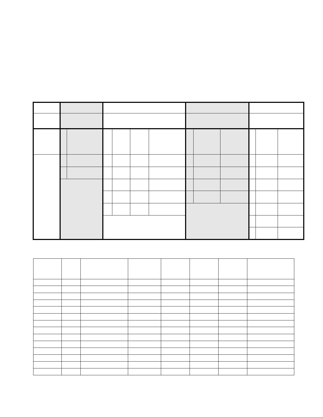
NXT Air-Powered Pumps
Your model number is marked on the pump identification plate located toward the rear of the air motor. To determine
the model number of your pump from the following matrix, select the six digits which describe your pump. The first
digit is always J for circulation pumps. The remaining five digits define the construction. For example, a circulation
pump with carbon steel construction, a 2.0:1 ratio, low noise exhaust, no communication option, npt fittings, and
chrome rod and cylinder is model number JC20L1. To order replacement parts, see page 18.
J C20 L1
First
Digit
J
(all
circulation
pumps)
Second Digit Third and Fourth Digit Fifth Digit Sixth Digit
Maximum
Fluid
Motor
Material
C Carbon Steel 20 2200 2000 200 (1.4, 14.0) L Low Noise none 1 npt Chromex/
S Stainless Steel 30 2200 1500 300 (2.1, 21.0) M Low Noise
Size
35 3400 2000 340 (2.3, 23.0) R Remote none 3 bspp* Chromex/
40 2200 1000 400 (2.8, 28.0) S Remote
45 3400 1500 460 (3.2, 32.0)
XX = X.X:1 ratio 7 npt Chromex/
Lower
Size
Pressure
psi (MPa, bar) Exhaust
Communi-
cation Fittings
™
DataTrak
DataTrak
2 npt Chromex/
™
4 bspp* Chromex/
5 tri-
clamp
6 tri-
clamp
Rod and
Cylinder
Chrome
MaxLife
Chrome
MaxLife
Chromex/
Chrome
Chromex/
MaxLife
Nitride
Viscount I Plus Hydraulic-Powered Pumps
Maximum Pump
Working Pressure
Model No. Series
253642 A 300 (2.1, 21) npt sst Chromex Chrome 253033
253643 A 225 (1.6, 16) npt sst Chromex Chrome 253034
253644 A 300 (2.1, 21) npt sst Chromex MaxLife 253568
253645 A 225 (1.6, 16) npt sst Chromex MaxLife 253569
253646 A 300 (2.1, 21) npt cst Chromex Nitride 253061
253647 A 225 (1.6, 16) npt cst Chromex Nitride 253062
253648 A 300 (2.1, 21) bspp* sst Chromex Chrome 253423
253649 A 225 (1.6, 16) bspp* sst Chromex Chrome 253085
253650 A 300 (2.1, 21) bspp* sst Chromex MaxLife 253398
253651 A 225 (1.6, 16) bspp* sst Chromex MaxLife 253397
253652 A 300 (2.1, 21) tri-clamp sst Chromex Chrome 253520
253653 A 225 (1.6, 16) tri-clamp sst Chromex Chrome 253521
253654 A 300 (2.1, 21) tri-clamp sst Chromex MaxLife 253523
253655 A 225 (1.6, 16) tri-clamp sst Chromex MaxLife 253524
*BSPP models require inlet and outlet seals to perform optimally. See Accessories, page 9.
311211L 3
psi (MPa, bar)
Connection
Style Material
Rod
Material
Cylinder
Material
High-Flo Lower
(see manual 311690)
Page 4

Models
Viscount II Hydraulic Powered Pumps
Maximum Pump
Working Pressure
Model No. Series
247355 A 460 (3.2, 32) npt sst Chromex Chrome 253035
247356 A 460 (3.2, 32) npt cs Chromex Chrome 253063
247357 A 460 (3.2, 32) bspp* sst Chromex Chrome 253086
247358 A 460 (3.2, 32) bspp* sst Chromex MaxLife 253396
247359 A 460 (3.2, 32) tri-clamp sst Chromex Chrome 253522
247360 A 460 (3.2, 32) tri-clamp sst Chromex MaxLife 253525
247361 A 460 (3.2, 32) npt sst Chromex MaxLife 253570
*BSPP models require inlet and outlet seals to perform optimally. See Accessories, page 9.
psi (MPa, bar)
Connection
Style Material
Rod
Material
Cylinder
Material
High-Flo Lower
(see manual 311690)
4 311211L
Page 5
Warnings
Warnings
The following warnings are for the setup, use, grounding, maintenance, and repair of this equipment. The exclamation point symbol alerts you to a general warning and the hazard symbol refers to procedure-specific risk. Refer back
to these warnings. Additional, product-specific warnings may be found throughout the body of this manual where
applicable.
WARNING
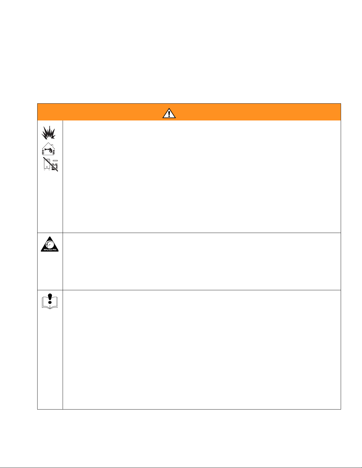
FIRE AND EXPLOSION HAZARD
Flammable fumes, such as solvent and paint fumes, in work area can ignite or explode. To help prevent
fire and explosion:
• Use equipment only in well ventilated area.
• Eliminate all ignition sources; such as pilot lights, cigarettes, portable electric lamps, and plastic drop
cloths (potential static arc).
• Keep work area free of debris, including solvent, rags and gasoline.
• Do not plug or unplug power cords, or turn power or light switches on or off when flammable fumes
are present.
• Ground all equipment in the work area. See Grounding instructions.
• Use only grounded hoses.
• Hold gun firmly to side of grounded pail when triggering into pail.
• If there is static sparking or you feel a shock, stop operation immediately. Do not use equipment
until you identify and correct the problem.
• Keep a working fire extinguisher in the work area.
PRESSURIZED EQUIPMENT HAZARD
Fluid from the gun/dispense valve, leaks, or ruptured components can splash in the eyes or on skin and
cause serious injury.
• Follow Pressure Relief Procedure in this manual, when you stop spraying and before cleaning,
checking, or servicing equipment.
• Tighten all fluid connections before operating the equipment.
• Check hoses, tubes, and couplings daily. Replace worn or damaged parts immediately.
EQUIPMENT MISUSE HAZARD
Misuse can cause death or serious injury.
• Do not operate the unit when fatigued or under the influence of drugs or alcohol.
• Do not exceed the maximum working pressure or temperature rating of the lowest rated system
component. See Technical Data in all equipment manuals.
• Use fluids and solvents that are compatible with equipment wetted parts. See Technical Data in all
equipment manuals. Read fluid and solvent manufacturer’s warnings. For complete information
about your material, request MSDS forms from distributor or retailer.
• Check equipment daily. Repair or replace worn or damaged parts immediately with genuine manufacturer’s replacement parts only.
• Do not alter or modify equipment.
• Use equipment only for its intended purpose. Call your distributor for information.
• Route hoses and cables away from traffic areas, sharp edges, moving parts, and hot surfaces.
• Do not kink or over bend hoses or use hoses to pull equipment.
• Keep children and animals away from work area.
• Comply with all applicable safety regulations.
311211L 5
Page 6
Warnings
WARNING
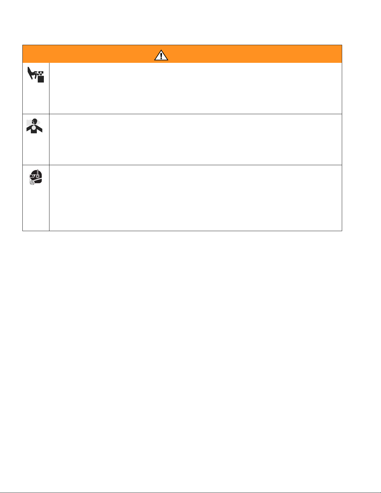
MOVING PARTS HAZARD
Moving parts can pinch or amputate fingers and other body parts.
• Keep clear of moving parts.
• Do not operate equipment with protective guards or covers removed.
• Pressurized equipment can start without warning. Before checking, moving, or servicing equipment,
follow the Pressure Relief Procedure in this manual. Disconnect power or air supply.
TOXIC FLUID OR FUMES HAZARD
Toxic fluids or fumes can cause serious injury or death if splashed in the eyes or on skin, inhaled, or
swallowed.
• Read MSDS’s to know the specific hazards of the fluids you are using.
• Store hazardous fluid in approved containers, and dispose of it according to applicable guidelines.
• Always wear impervious gloves when spraying or cleaning equipment.
PERSONAL PROTECTIVE EQUIPMENT
You must wear appropriate protective equipment when operating, servicing, or when in the operating
area of the equipment to help protect you from serious injury, including eye injury, inhalation of toxic
fumes, burns, and hearing loss. This equipment includes but is not limited to:
• Protective eyewear
• Clothing and respirator as recommended by the fluid and solvent manufacturer
•Gloves
• Hearing protection
6 311211L
Page 7
Installation
Installation
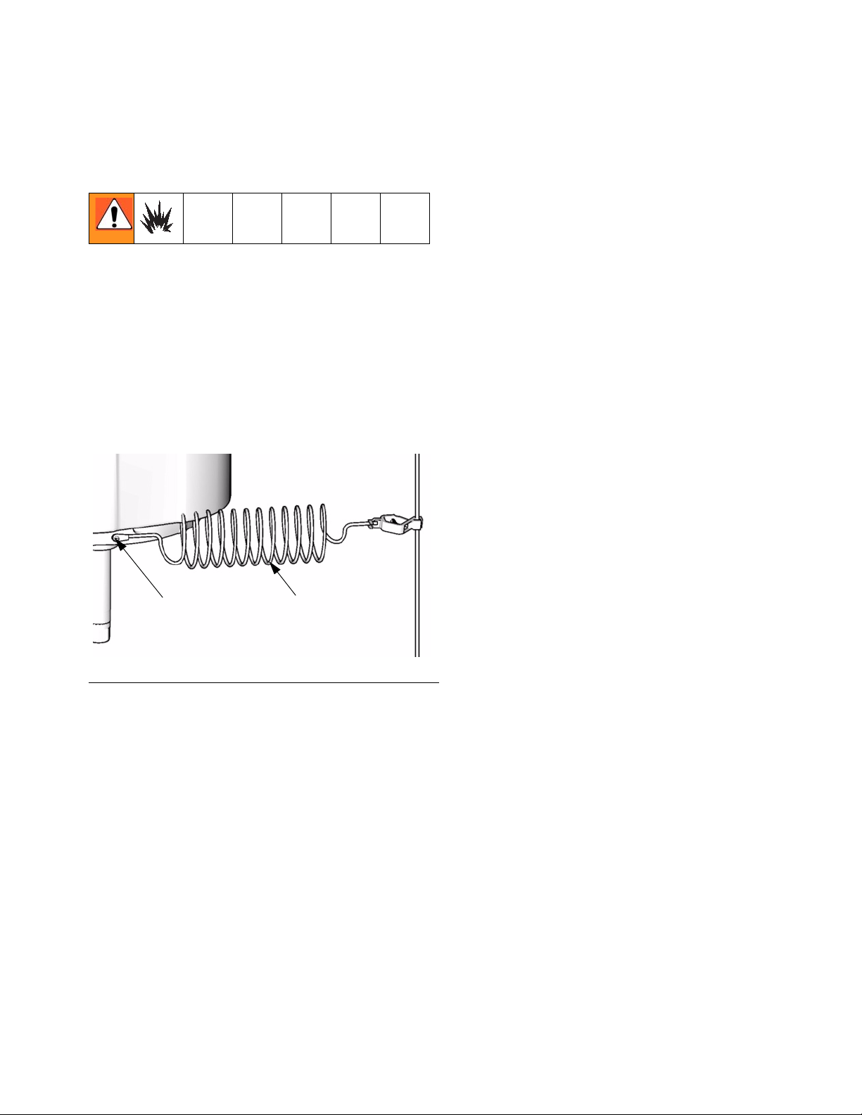
Grounding
The equipment must be grounded. Grounding reduces
the risk of static and electric shock by providing an
escape wire for the electrical current due to static build
up or in the event of a short circuit.
Pump: Use a ground screw (Z) and lockwasher on the
motor to attach ground wire 244524 (Y). Tighten the
screw securely. Connect the other end of the ground
wire to a true earth ground. See F
IG. 1.
Object being sprayed: follow local code.
Solvent pails used when flushing: follow local code.
Use only conductive metal pails, placed on a grounded
surface. Do not place the pail on a nonconductive surface, such as paper or cardboard, which interrupts
grounding continuity.
To maintain grounding continuity when flushing or
relieving pressure: hold metal part of the spray gun
firmly to the side of a grounded metal pail, then trigger
the gun.
Z Y
TI8250a
FIG. 1
Air and fluid hoses: use only electrically conductive
hoses with a maximum of 500 ft. (150 m) combined
hose length to ensure grounding continuity. Check the
electrical resistance of hoses. If total resistance to
ground exceeds 29 megohms, replace hose immediately.
Air compressor: follow manufacturer’s recommendations.
Hydraulic power supply: follow manufacturer’s recommendations.
Surge tank: use a ground wire and clamp.
Spray gun: ground through a connection to a properly
grounded fluid hose and pump.
Fluid supply container: follow local code.
311211L 7
Page 8
Installation
Accessories
Install the following accessories in the order shown in
F
IG. 2 and FIG. 3, using adapters as necessary.
Air-Powered Pumps
For typical installation, see FIG. 2 on page 10.
Accessory Air Control Kits are available for the NXT
Air Motor. The kits include a master air valve, air
regulator, and filter. Order the kits separately. See
manual 311239 for more information.
Air Line
• Bleed-type master air valve (M): required in your
system to relieve air trapped between it and the air
motor when the valve is closed.
Trapped air can cause the pump to cycle unexpectedly,
which could result in serious injury from splashing or
moving parts.
Hydraulic-Powered Pumps
For typical installation, see FIG. 3 on page 11.
Hydraulic Power Supply
CAUTION
The hydraulic power supply must be kept clean at all
to avoid damage to the motor and hydraulic power
supply.
1. Blow out hydraulic lines with air and flush thoroughly before connection to the motor.
2. Plug hydraulic inlets, outlets, and line ends when
disconnecting them for any reason.
Be sure the power supply can provide sufficient power to
the motor. Be sure the power supply is equipped with a
suction filter to the hydraulic pump.
Hydraulic Supply Line
• For Viscount I Plus motors, the hydraulic inlet
on the motor is 3/4 in., 37° flare. Use a minimum 1/2 in. (13 mm) ID hydraulic supply line
(K).
Be sure the valve is easily accessible from the pump
and located downstream from the air regulator. Be sure
the air bleed hole points away from the operator.
The air motor is rated to 100 psi (0.7 MPa, 7.0 bar). If
you will apply more than 100 psi (0.7 MPa, 7.0 bar) to
the system, install a safety relief valve between the
bleed-type master air valve and the air motor.
• Pump air regulator (L): to control pump speed and
outlet pressure. Locate close to the pump.
• Air line filter (K): removes harmful dirt and mois-
ture from compressed air supply.
• Second bleed-type air valve (M): isolates air line
accessories for servicing. Locate upstream from all
other air line accessories.
• For Viscount II motors, use a minimum 13 mm
(1/2 in.) ID supply line supply line (K). The
motor has a 3/4 npt(f) hydraulic oil supply fitting.
• Supply line shutoff valve (S): isolates the motor
when servicing the system. See F
• Hydraulic fluid pressure gauge (P): monitors the
hydraulic oil pressure to the motor to avoid overpressurizing the motor or lower.
• Pressure- and temperature-compensated flow
control valve (T): prevents the motor from running
too fast, which can damage it.
• Pressure reducing valve (N), which has a drain
line (M) running to the return line (K): controls the
hydraulic pressure to the motor.
IG. 3.
8 311211L
Page 9
Installation
Hydraulic Return Line
• For Viscount I Plus motors, the hydraulic outlet
on the motor is 7/8 in., 37° flare. Use a minimum 5/8 in. (16 mm) ID hydraulic return line
(J).
• For Viscount II motors, use a minimum 22 mm
(7/8 in.) ID return line (J). The motor has a 1 in.
npt(f) hydraulic oil return fitting.
• Return line shutoff valve (R): isolates the motor
when servicing the system.
CAUTION
To avoid damage to the pump, never use the return
line shutoff valve to control the hydraulic flow. Do not
install any flow control devices on the hydraulic return
line.
• Return fluid filter (J): removes residue from the
hydraulic fluid to help keep the system running
smoothly (10 micron size).
All Pumps
Fluid Line
• Fluid filter: with a 60 mesh (250 micron) stainless
steel element to filter particles from the fluid as it
leaves the pump.
• Fluid drain valve (U): required in your system, to
relieve fluid pressure in the hose and gun.
• Fluid shutoff valve (D): shuts off fluid flow.
• Fluid pressure regulator: for more precise adjust-
ment of the fluid pressure.
• Gun or valve: to dispense fluid.
• Fluid line swivel: for easier gun movement.
• Suction kit: enables the pump to draw fluid from a
container.
• Inlet and outlet seals: prevent leakage in BSPP
models. Order 193423 for 1-1/2 in. inlet seal and
193422 for 1-1/4 in. outlet seal.
311211L 9
Page 10

Installation
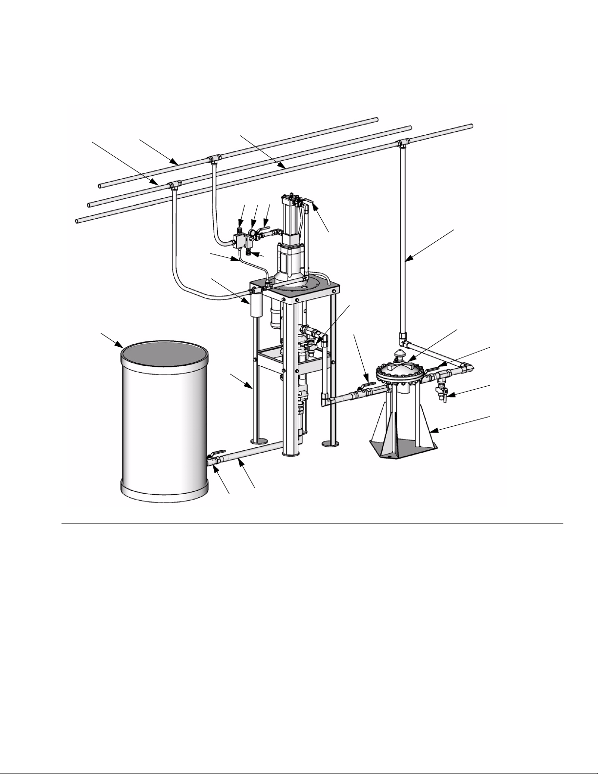
Air-Powered Pumps Typical Installation
M
J
M
KL
B
N
GNDD
E
A
D
FIG. 2: Typical Installation
Key:
A Mix Tank
B Pump Stand
C Fluid Supply Line; 1-1/2 in. (38 mm) minimum diameter
D Fluid Shutoff Valve
E Fluid Line; 1 in. (25 mm) minimum diameter
F Surge Tank Stand
G Surge Tank
H Ground Wire (required, see page 7 for installation)
J Air Supply Line
K Air Line Filter
L Air Regulator and Gauge
M Bleed-Type Master Air Valve (required)
N Fluid Drain Valve (required)
F
C
TI8398a
10 311211L
Page 11
Hydraulic-Powered Pumps Typical Installation
Installation
K
A
L
M
E
S
N
P
E
R
T
J
U
D
B
G
D
U
C
D
FIG. 3: Typical Installation
Key:
AMix Tank
B Pump Stand
C Fluid Supply Line; 1-1/2 in. (38 mm) minimum diameter
D Fluid Shutoff Valve
E Fluid Line; 1 in. (25 mm) minimum diameter
F Surge Tank Stand
G Surge Tank
J 10 Micron Return Filter
K Hydraulic Return Line; 5/8 in. (16 mm) minimum diameter
L Hydraulic Supply Line; 1/2 in. (13 mm) minimum diameter
MDrain Line
N Pressure Reducing Valve
P Hydraulic Pressure Gauge
R Return Line Shutoff Valve
S Supply Line Shutoff Valve
T Flow Control Valve
F
TI8399a
U Fluid Drain Valve (required)
Y Ground Wire (required see page 7 for installation)
311211L 11
Page 12

Operation
Operation
Pressure Relief Procedure
1. Engage trigger lock.
2. Air-Powered Pumps only: Close the bleed-type
master air valve.
Hydraulic-Powered Pumps only: Shut off the
hydraulic supply line valve (S) first, then the return
line valve (R).
3. Disengage the trigger lock.
4. Hold a metal part of the gun firmly to a grounded
metal pail. Trigger the gun to relieve pressure.
5. Engage the trigger lock.
6. Open all fluid drain valves in the system, having
waste containers ready to catch drainage. Leave the
drain valves open until you are ready to spray again.
7. If you suspect the spray tip or hose is clogged or
that pressure has not been fully relieved after following the steps above, VERY SLOWLY loosen the tip
guard retaining nut or hose end coupling to relieve
pressure gradually, then loosen completely. Clear
hose or tip obstruction.
Pump Operation
• In a circulation system, the pump operates continuously until the power supply is shut off.
CAUTION
Do not allow the pump to run quickly for a long period
of time as this may damage the packings.
• In a direct-supply system, the pump starts
when the gun is opened, and stops when the
gun is closed.
• Perform a stall test periodically to ensure the
piston seal is in good working condition and
prevent system overpressurization:
• Close the fluid shutoff valve (D) closest to the
pump on the downstroke and be sure that the
pump stalls. Open the fluid shutoff valve to
restart the pump. Close the fluid shutoff valve
(D) closest to the pump on the upstroke and be
sure that the pump stalls.
Stop the Pump at the Bottom of
CAUTION
Hydraulic-Powered Pumps only: When shutting down
the hydraulic system, always shut off the hydraulic
supply line shutoff valve (S) first, and then the return
line shutoff valve (R) to prevent overpressurizing the
motor or its seals. When starting the hydraulic system, open the return line shutoff valve first.
Flush Before Using Equipment
The equipment was tested with lightweight oil, which is
left in the fluid passages to protect parts. To avoid contaminating your fluid with oil, flush the equipment with a
compatible solvent before using the equipment. See
Flushing, page 13.
Trigger Lock
Always engage the trigger lock when you stop spraying
to prevent the gun from being triggered accidentally by
hand or if dropped or bumped.
12 311211L
Its Stroke
Relieve the pressure when you stop the pump for any
reason. Stop the pump on the downstroke, before the air
motor changes over.
CAUTION
Failure to stop the pump at the bottom of its stroke
allows fluid to dry on the piston rod, which can cause
damage to the throat packings when the pump is
restarted.
Hydraulic-Powered Pumps only: Always shut off the
supply line shutoff valve (S) first, and then the
return line shutoff valve (R). This is to prevent overpressurizing the motor or its seals.
Page 13

Maintenance
Maintenance
Preventive Maintenance Schedule
The operating conditions of your particular system
determine how often maintenance is required. Establish
a preventive maintenance schedule by recording when
and what kind of maintenance is needed, and then
determine a regular schedule for checking your system.
Your maintenance schedule should include the following:
Flushing
• Flush before shutting down the system for an
extended period of time.
• Flush before repairing the pump, if possible.
• Flush before fluid can dry out, settle, or set up
in the equipment.
Air Line Filter
Drain and clean as necessary.
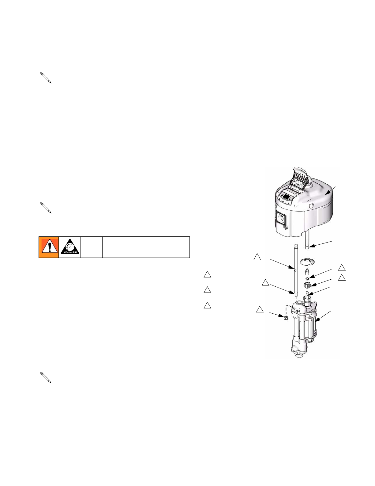
Excessive Leaking at Throat
If you see excessive leaking at the throat, tighten the
packing nut (21), see F
lem, replace the throat packings, piston rod, or both See
manual 311690.
NXT Air-Powered
Pump Shown
1
packing nut
1
Torque to 15-20 ft-lb (20-27 N•m).
F
IG. 4
IG. 4. If this does not fix the prob-
TI8354a
Hydraulic Power Supply Check
Carefully follow the hydraulic power supply manufacturer's recommendations on reservoir and filter cleaning,
and periodic changes of hydraulic fluid.
Mix Tank Volume
Don't let the mix tank run dry. When the tank is empty,
the pump demands more power as it tries to suck in
some fluid. This causes the pump to run too fast, which
can seriously damage the pump.
Packing Nut Tightness
Check the packing nut (21) tightness every few days at
startup and then weekly throughout the life of the throat
seal. The packing nut should be tight enough to stop
leakage, but no tighter. See F
To check the adjustment of the packing nut, stop the
pump and relieve fluid pressure. Loosen the packing nut
until it turns freely. Tighten the nut firmly and then turn
the nut another 1/4 turn. If you have a torque wrench,
tighten the packing nut to 30 ft-lb (40 N•m), then back off
and re-tighten to 15-20 ft-lb (20-27 N•m).
IG. 4.
311211L 13
Page 14

Troubleshooting
Troubleshooting
1. Relieve the pressure.
2. Check all possible problems and solutions before
disassembling pump.
PROBLEM CAUSE SOLUTION
Pump output low on both strokes. Restricted air or hydraulic supply lines. Clear any obstructions; be sure all shutoff
valve are open; increase pressure, but do
not exceed maximum working pressure.
Exhausted fluid supply. Refill and reprime pump.
Clogged fluid outlet line, valves, etc. Clear.
Worn piston packing. Replace. See lower manual 311690.
Pump output low on only one stroke. Held open or worn ball check valves. Check and repair.
Worn piston packings. Replace. See lower manual 311690.
Pump operates erratically. Exhausted fluid supply. Refill and reprime pump.
Held open or worn ball check valves. Check and repair.
Worn piston packing. Replace. See lower manual 311690.
Excessive hydraulic fluid supply pressure
to Viscount motor.
Pump will not operate. Restricted air or hydraulic supply lines. Clear any obstructions; be sure all shut
Exhausted fluid supply. Refill and reprime pump.
Clogged fluid outlet line, valves, etc. Clear.
Damaged air motor or hydraulic motor. See air motor manual 311238 or hydrau-
Fluid dried on piston rod. Disassemble and clean pump. See lower
Pump will not prime Suction line clogged. Clear. Flush more frequently.
Held open or worn ball check valves. Check and repair.
Piston assembled with wrong nut. Use only the large, round, special nut.
Excessive throat leakage. Worn piston rod or throat packings. Replace. See lower manual 311690.
Pump will not stall when fluid is shut off. Warn ball check valves. Check and repair.
Worn piston packing. Replace. See lower manual 311690.
See Viscount I Plus motor manual
308330 or Viscount II manual 308048.
off valves are open; increase pressure,
but do not exceed maximum working
pressure.
lic motor manual 308330 or 308048.
manual 311690. In future, stop pump at
bottom of stroke.
14 311211L
Page 15
Repair
• To service the lower, see manual 311690.
Repair
tie rods. Tighten the locknuts and torque to 50-55
ft-lb (68-75 N•m).
• To service the air motor, see manual 311238.
• To service the Viscount I Plus hydraulic motor,
see manual 308330.
• To service the Viscount II hydraulic motor, see
manual 308048.
Disconnect the Lower
To service the lower, follow the procedure on this page,
and disassemble the pump as described in manual
311690. To disconnect pump from an electric circulation
assembly, EPXXXX, see manual 311594.
In stand or wall-mounted installations, you do not
have to remove the entire pump from its mounting.
1. Relieve the pressure, see Pressure Relief Procedure page 12.
2. Disconnect the hoses from the lower and plug the
ends to prevent fluid contamination.
3. Loosen the coupling nut (K) and remove the collars
(G). Remove the coupling nut from the piston rod
(H). Unscrew the locknuts (B) from the tie rods (C).
Pull the lower (D) off the motor (E). See F
F
IG. 6.
IG. 5 and
3. Insert the collars (G) into the coupling nut (K).
Tighten the coupling nut onto the piston rod (H) and
torque to 90-100 ft-lb (122-135 N•m).
4. Flush and test the pump before reinstalling it in the
system. Connect hoses and flush the pump. While it
is pressurized, check for smooth operation and
leaks. Adjust or repair as necessary before reinstalling in the system. Reconnect the pump ground wire
before operating.
NXT Pump
E
Shown
F
2
C
3
G
1
Torque to 90-100 ft-lb
(122-135 N•m).
2
Torque to 50-60 ft-lb
(68-81 N•m).
3
Apply lubricant.
3
2
B
1
K
H
D
Reconnect the Lower
FIG. 5
TI8394b
If the coupling rod (F) and tie rods (C) have been
disassembled from the motor, see Reassemble the
Coupling Rod and Tie Rods to the Motor on page
16.
1. Assemble the coupling nut (K) to the piston rod (H).
2. Orient the lower (D) to the motor (E). Position the
lower on the tie rods (C). Lubricate the threads of
the tie rods. Screw the tie rod locknuts (B) onto the
311211L 15
Page 16

Repair
Viscount I Plus
Pump Shown
3
4. Align the lower (D) with the tie rods (C) and loosely
install the tie rod locknuts (B).
5. Insert the collars (G) and screw the coupling nut (K)
onto the coupling rod (F) and torque to 90-100 ft-lb
E
(122-135 N•m).
6. For Viscount I Plus pumps, torque the holding the
J
adapter plate (J) to the motor (E) to 15-17 ft-lb
(20-23 N•m). For Viscount I Plus and Viscount II
pumps, torque the tie rod locknuts (B) to 50-55 ft-lb
C
A
F
(68-75 N•m).
1
G
K
H
1
Torque to 90-100 ft-lb
(122-135 N•m).
2
Torque to 50-55 ft-lb
(68-75 N•m).
3
Lubricate threads.
F
IG. 6
2
B
D
TI7674b
Reassemble the Coupling Rod and Tie Rods to the Motor
Use this procedure only if the coupling rod (F) and
tie rods (C) have been disassembled from the
motor, to ensure proper alignment of the motor
shaft to the piston rod.
1. Loosen, but do not remove, the screws holding the
adapter plate (J) to the motor (E), on Viscount I Plus
pumps. See F
screw (N) to 50-55 ft-lb (68-75 N•m) into motor (E).
2. Screw the tie rods (C) into the adapter plate (J) and
torque to 50-55 ft-lb (68-75 N•m). On Viscount I Plus
pumps, the tie rods will engage threaded holes in
the base of the motor. Viscount II pumps will engage
into the adapter plate (J).
IG. 6. For Viscount II pumps, torque
Viscount II 460
Pump Shown
1
Torque to 90-100 ft-lb
(122-135 N•m).
2
Torque to 50-55 ft-lb
(68-75 N•m).
3
Lubricate threads.
FIG. 7
E
J
3
2
F
M
1
G
K
TI10466a
N
H
D
C
3
2
B
3. Fill the cavity in the bottom of the motor shaft with
grease. Screw the coupling rod (F) into the motor
shaft until the pin holes align. Install the pin (A) in
the first hole from the end of the coupling. On Viscount II pumps, torque the coupling nut (M) into the
motor shaft.
16 311211L
Page 17

Repair
311211L 17
Page 18

Parts
Parts
NXT Pumps
101
Common Parts
Ref.
No. Description Part No. Qty.
101 MOTOR, NXT, see manual 311238 see table,
page 19
102 LOWER, High-Flo, see manual 311690 see table,
page 19
103 NUT, coupling 184059 1
104 COLLAR, coupling 184128 2
105 ADAPTER, coupling 15H369 1
106 TIE ROD, 14.25 in. (362 mm) between
shoulders
107 NUT, lock, hex; 9/16-12 unc 108683 3
108 COVER, moisture 247362 1
15G924 3
1
1
106
107
108
105
104
103
102
TI8394b
18 311211L
Page 19

Parts That Vary by Model
Parts
101 102
Air-Powered
Pump
(see page 3)
JC20L1 N22LN0 253063
JC20M1 N22LT0 253063
JC30L7 N22LN0 253062
JC30M7 N22LT0 253062
JC35L1 N34LN0 253063
JC35M1 N34LT0 253063
JC40L7 N22LN0 253061
JC40M7 N22LT0 253061
JC45L7 N34LN0 253062
JC45M7 N34LT0 253062
JS20L1 N22LN0 253035
JS20L2 N22LN0 253570
JS20L3 N22LN0 253086
JS20L4 N22LN0 253396
JS20L5 N22LN0 253522
JS20L6 N22LN0 253525
JS20M1 N22LT0 253035
JS20M2 N22LT0 253570
JS20M3 N22LT0 253086
JS20M4 N22LT0 253396
JS20M5 N22LT0 253522
JS20M6 N22LT0 253525
JS20R1 N22RN0 253035
JS20R2 N22RN0 253570
JS20R3 N22RN0 253086
JS20R4 N22RN0 253396
JS20R5 N22RN0 253522
JS20R6 N22RN0 253525
JS20S1 N22RT0 253035
JS20S2 N22RT0 253570
JS20S3 N22RT0 253086
JS20S4 N22RT0 253396
JS20S5 N22RT0 253522
JS20S6 N22RT0 253525
JS30L1 N22LN0 253034
JS30L2 N22LN0 253569
JS30L3 N22LN0 253085
JS30L4 N22LN0 253397
JS30L5 N22LN0 253521
JS30L6 N22LN0 253524
JS30M1 N22LT0 253034
JS30M2 N22LT0 253569
JS30M3 N22LT0 253085
JS30M4 N22LT0 253397
JS30M5 N22LT0 253521
JS30M6 N22LT0 253524
JS30R1 N22RN0 253034
JS30R2 N22RN0 253569
JS30R3 N22RN0 253085
JS30R4 N22RN0 253397
JS30R5 N22RN0 253521
JS30R6 N22RN0 253524
JS30S1 N22RT0 253034
JS30S2 N22RT0 253569
JS30S3 N22RT0 253085
JS30S4 N22RT0 253397
JS30S5 N22RT0 253521
JS30S6 N22RT0 253524
JS35L1 N34LN0 253035
NXT Air Motor
(see manual 311238)
High-Flo Lower
(see manual 311690)
101 102
Air-Powered
Pump
(see page 3)
JS35L2 N34LN0 253570
JS35L3 N34LN0 253086
JS35L4 N34LN0 253396
JS35L5 N34LN0 253522
JS35L6 N34LN0 253525
JS35M1 N34LT0 253035
JS35M2 N34LT0 253570
JS35M3 N34LT0 253086
JS35M4 N34LT0 253396
JS35M5 N34LT0 253522
JS35M6 N34LT0 253525
JS35R1 N34RN0 253035
JS35R2 N34RN0 253570
JS35R3 N34RN0 253086
JS35R4 N34RN0 253396
JS35R5 N34RN0 253522
JS35R6 N34RN0 253525
JS35S1 N34RT0 253035
JS35S2 N34RT0 253570
JS35S3 N34RT0 253086
JS35S4 N34RT0 253396
JS35S5 N34RT0 253522
JS35S6 N34RT0 253525
JS40L1 N22LN0 253033
JS40L2 N22LN0 253568
JS40L3 N22LN0 253423
JS40L4 N22LN0 253398
JS40L5 N22LN0 253520
JS40L6 N22LN0 253523
JS40M1 N22LT0 253033
JS40M2 N22LT0 253568
JS40M3 N22LT0 253423
JS40M4 N22LT0 253398
JS40M5 N22LT0 253520
JS40M6 N22LT0 253523
JS40R1 N22RN0 253033
JS40R2 N22RN0 253568
JS40R3 N22RN0 253423
JS40R4 N22RN0 253398
JS40R5 N22RN0 253520
JS40R6 N22RN0 253523
JS40S1 N22RT0 253033
JS40S2 N22RT0 253568
JS40S3 N22RT0 253423
JS40S4 N22RT0 253398
JS40S5 N22RT0 253520
JS40S6 N22RT0 253523
JS45L1 N34LN0 253034
JS45L2 N34LN0 253569
JS45L3 N34LN0 253085
JS45L4 N34LN0 253397
JS45L5 N34LN0 253521
JS45L6 N34LN0 253524
JS45M1 N34LT0 253034
JS45M2 N34LT0 253569
JS45M3 N34LT0 253085
JS45M4 N34LT0 253397
JS45M5 N34LT0 253521
JS45M6 N34LT0 253524
NXT Air Motor
(see manual 311238)
High-Flo Lower
(see manual 311690)
311211L 19
Page 20

Parts
101 102
Air-Powered
Pump
(see page 3)
JS45R1 N34RN0 253034
JS45R2 N34RN0 253569
JS45R3 N34RN0 253085
JS45R4 N34RN0 253397
JS45R5 N34RN0 253521
JS45R6 N34RN0 253524
JS45S1 N34RT0 253034
JS45S2 N34RT0 253569
JS45S3 N34RT0 253085
JS45S4 N34RT0 253397
JS45S5 N34RT0 253521
JS45S6 N34RT0 253524
NXT Air Motor
(see manual 311238)
High-Flo Lower
(see manual 311690)
20 311211L
Page 21

Viscount I Plus Pumps
101
111
Parts
Common Parts
Ref.
No. Description Part No. Qty.
101 MOTOR, Viscount 1+, see manual
308330
102 LOWER, High-Flo, see manual 311690 see table,
103 TIE ROD, 14.25 in. (362 mm) between
shoulders
104 NUT, lock, hex; 9/16-12 unc 108683 3
105 NUT, coupling 184059 1
106 COLLAR, coupling 184128 2
107 PIN, cotter 100103 1
108 ADAPTER, coupling 15H838 1
109 SCREW, cap 100001 4
110 WASHER, lock 100214 4
111 PLATE, adapter 189206 1
261466 1
below
15G924 3
Parts That Vary by Model
1
103
104
107
110
109
108
106
105
102
Hydraulic-Powered Pump
(see page 3)
253642 253033
253643 253034
253644 253568
253645 253569
253646 253061
253647 253062
253648 253423
253649 253085
253650 253398
253651 253397
253652 253520
253653 253521
253654 253523
253655 253524
102
High-Flo Lower
(see manual 311690)
TI7674b
311211L 21
Page 22

Parts
Viscount II 460 Pumps
103
101
Common Parts
Ref.
No. Description Part No. Qty.
101 MOTOR, Viscount II, see manual
308048
102 LOWER, High-Flo, see manual 311690 see table,
103 TIE ROD, 14.25 in. (362 mm) between
shoulders
104 NUT, lock, hex; 9/16-12 unc 108683 3
105 NUT, coupling 184059 1
106 COLLAR, coupling 184128 2
108 ADAPTER, coupling 15K736 1
109 SCREW, cap, socket hd C19789 3
110 NUT, coupling 183079 1
111 BRACKET, mounting 120558 1
223646 1
below
15G924 3
Parts That Vary by Model
1
111
103
104
110
106
105
108
109
102
Hydraulic-Powered Pump
(see page 3)
247355 253035
247356 253063
247357 253086
247358 253396
247359 253522
247360 253525
247361 253570
102
High-Flo Lower
(see manual 311690)
TI10467a
22 311211L
Page 23
Dimensions
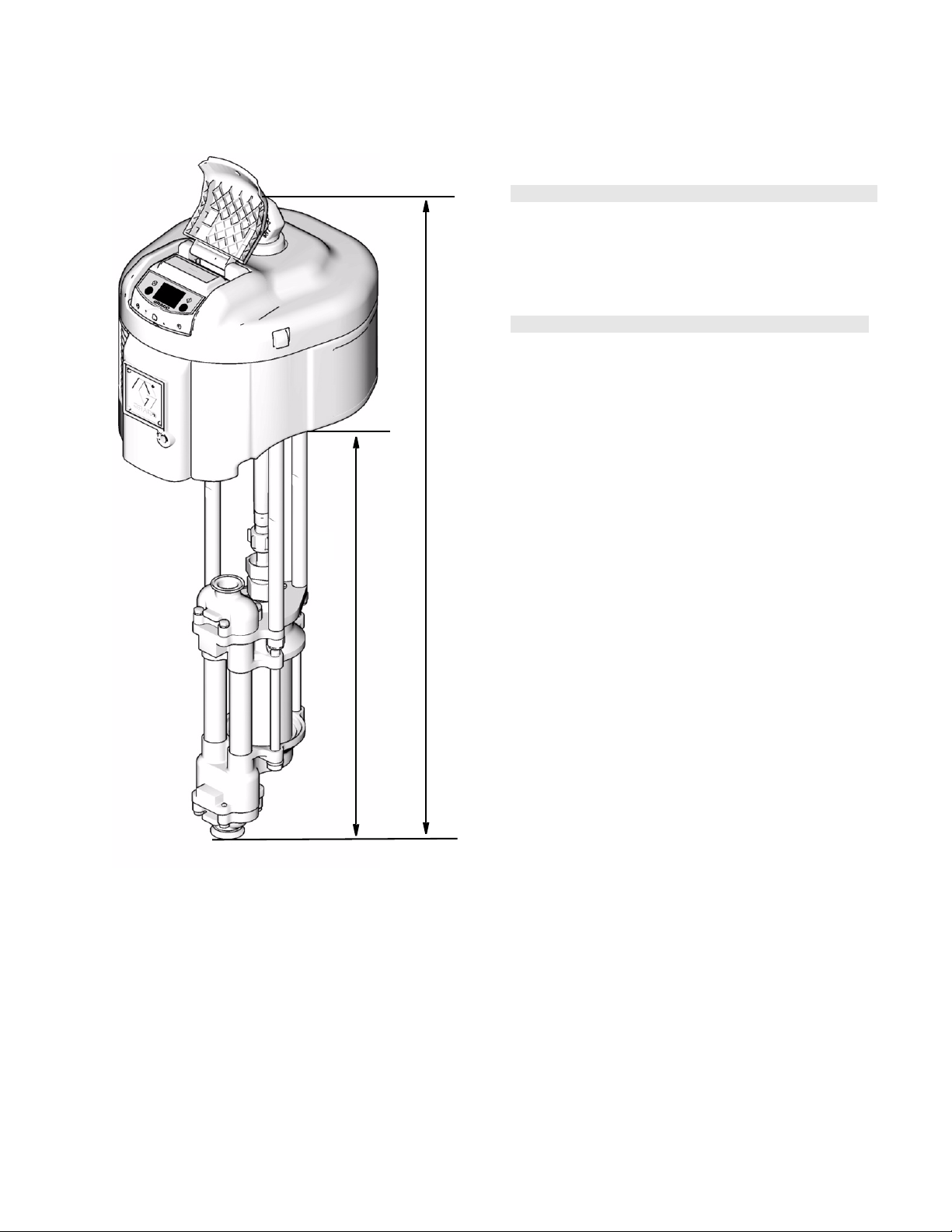
Dimensions
A
Air-Powered Pumps
Approx.
B
Pump ModelAin. (mm)
NXT cst 45.60 (1158) 28.78 (731) 96 (43)
in. (mm)
Weight
lb (kg)
Hydraulic-Powered Pumps
Approx.
A
Pump Model
Viscount I Plus cst 49.00 (1245) 28.78 (731) 76 (35)
Viscount II 53.72 (1365) 28.78 (731) 144 (65)
in. (mm)
B
in. (mm)
Weight
lb (kg)
TI8354a
B
311211L 23
Page 24
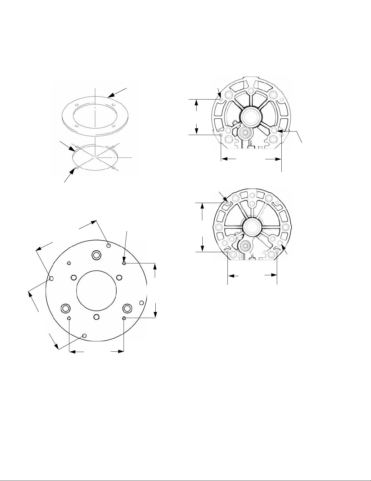
Pump Mounting Hole Diagram
)
Pump Mounting Hole Diagram
Viscount I Plus Models
9.75 in.
(247.7 mm)
Four 0.44 in. (11.1 mm)
diameter holes on 10.5 in.
bolt circle
Viscount II Models
7.43 in.
(188 mm)
Gasket
161806
4X 3/8-16 UNC - 2B
Four 3/8-16
Mounting Holes
3.938 in.
(100 mm)
Four 3/8-16
Mounting Holes
6.186 in.
(157 mm)
NXT 2200
6.750 in.
(172 mm)
NXT 3400
Three 5/8-11 Tie
Rod Holes
5.906 in. (150 mm
x 120° Bolt Circle
TI8071A
7.43 in.
(188 mm)
6.186 in.
(157 mm)
6.186 in.
(157 mm)
6.186 in.
(157 mm)
Six 5/8-11 Tie
Rod Holes
8.000 in. (203 mm)
x 120° Bolt Circle
5.906 in. (150 mm)
x 120° Bolt Circle
TI8070A
24 311211L
Page 25

Technical Data
NXT
Fluid Flow at
Maximum
Working Pressure
Model
JX20XX 200 (1.4, 14)
JX30XX 300 (2.1, 21) 23 (88) 2.6 (0.7)
JX35XX 350 (2.4, 24) 32 (121) 1.9 (0.5)
JX40XX 400 (2.8, 28) 17 (64) 3.6 (0.9)
JX45XX 450 (3.1, 31) 23 (88) 2.6 (0.7)
psi (MPa, bar)
See 311238 for Sound information.
Viscount I Plus Pumps
Air Operating
Range
psi (MPa, bar) Air Consumption
100 (0.7, 7.0) See Performance Chart
60 cycles per
minute
gpm (lpm)
32 (121) 1.9 (0.5)
Pump Cycles
per Gallon
(Liter)
Technical Data
Maximum
Fluid
Temperature
Rating
°F (°C)
150° (66°)
Maximum
Working
Pressure
Model
253642 300 (2.1, 21)
253643 225 (1.6, 16) 20 (74) 3.1 (0.8)
253644 300 (2.1, 21) 14 (54) 4.2 (1.1)
253645 225 (1.6, 16) 20 (74) 3.1 (0.8)
253646 300 (2.1, 21) 14 (54) 4.2 (1.1)
253647 225 (1.6, 16) 20 (74) 3.1 (0.8)
253648 300 (2.1, 21) 14 (54) 4.2 (1.1)
253649 225 (1.6, 16) 20 (74) 3.1 (0.8)
253650 300 (2.1, 21) 14 (54) 4.2 (1.1)
253651 225 (1.6, 16) 20 (74) 3.1 (0.8)
253652 300 (2.1, 21) 14 (54) 4.2 (1.1)
253653 225 (1.6, 16) 20 (74) 3.1 (0.8)
253654 300 (2.1, 21) 14 (54) 4.2 (1.1)
253655 225 (1.6, 16) 20 (74) 3.1 (0.8)
psi (MPa, bar)
Maximum
Hydraulic Working
Pressure
psi (MPa, bar)
1500 (10.3, 103)
Hydraulic Oil
Consumption
See Performance
Chart
Maximum
Hydraulic
Motor Fluid
Temperature
134°F (54°C)
Fluid Flow at
60 cycles per
minute
gpm (lpm)
14 (54) 4.2 (1.1)
per Gallon
Pump
Cycles
(Liter)
Viscount II Pumps
Model
247355
247356
247357
247358
247359
247360
247361
Maximum
Working
Pressure
psi (MPa, bar)
460 (3.2, 32) 1200 (8.3, 83)
Maximum
Hydraulic Working
Pressure
psi (MPa, bar)
Hydraulic Oil
Consumption
See Performance
Chart
Maximum
Hydraulic
Motor Fluid
Temperature
134°F (54°C) 31.7 (120) 1.89 (0.50) 150°F (66°C)
Fluid Flow at
60 cycles per
minute
gpm (lpm)
Pump
Cycles
per Gallon
(Liter)
Maximum
Fluid
Temperature
Rating
150°F (66°C)
Maximum
Fluid
Temperature
Rating
311211L 25
Page 26

Performance Charts
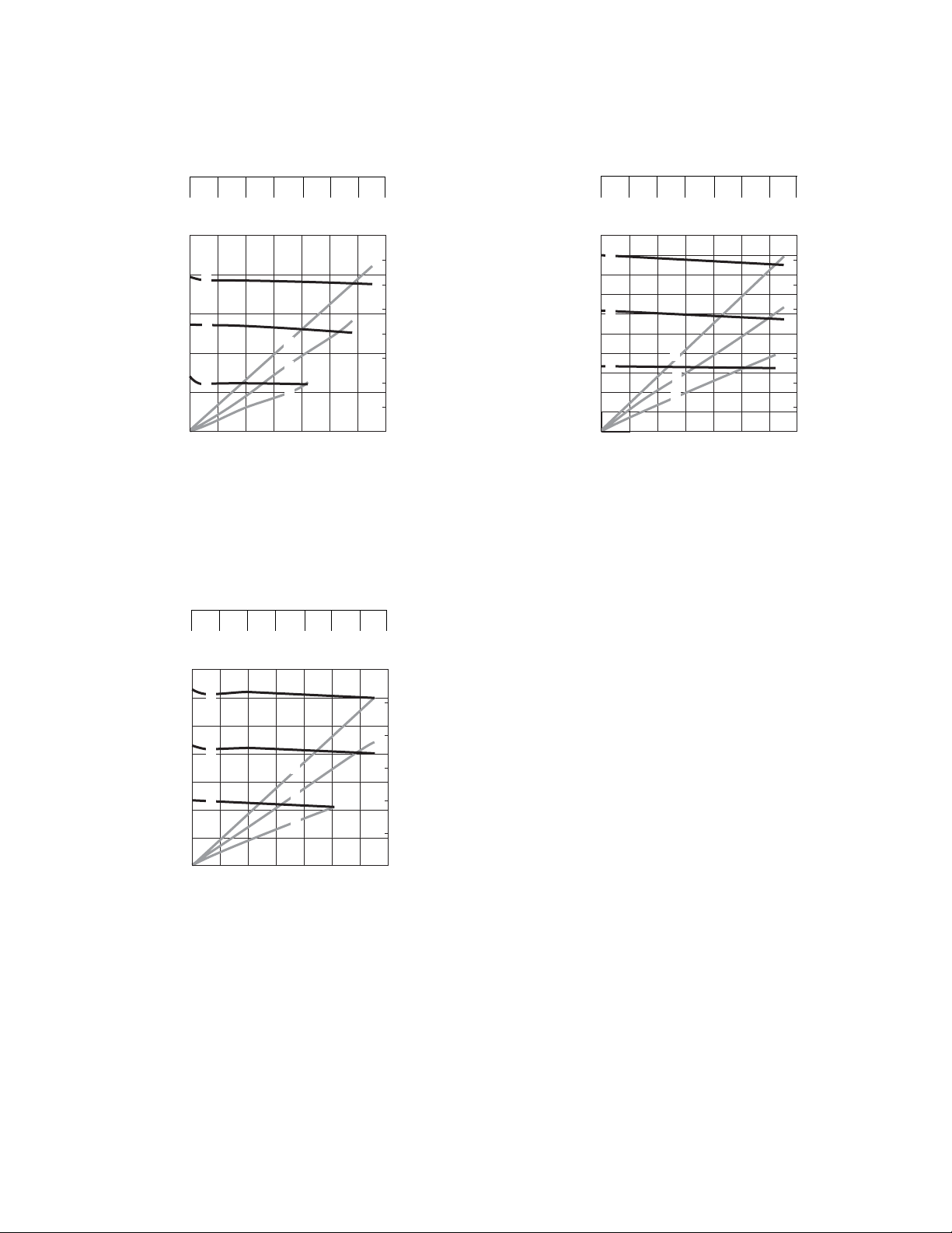
Performance Charts
Air-Powered Pumps
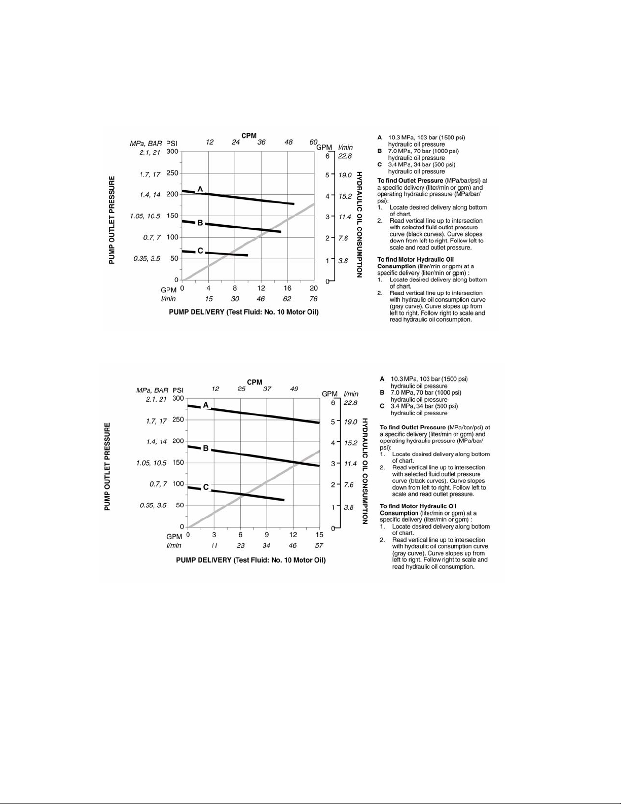
Fluid Outlet Pressure - Black Curves
To find Fluid Outlet Pressure (psi/MPa/bar) at a specific fluid
flow (gpm/lpm) and operating air pressure (psi/MPa/bar):
1. Locate desired flow along bottom of chart.
2. Follow vertical line up to intersection with selected fluid
outlet pressure curve (black).
3. Follow left to scale to read fluid outlet pressure.
Key:
A 100 psi (0.7 MPa, 7.0 bar) air pressure
B 70 psi (0.49 MPa, 4.9 bar) air pressure
C 40 psi (0.28 Mpa, 2.8 bar) air pressure
2200cc NXT Air Motor, 1000cc High-Flo Lower
CYCLES PER MIN.
10.0
(37.9)
39
12.0
(45.4)
45
SCFM (m
70 (1.96)
60 (1.68)
50 (1.40)
40 (1.12)
30 (0.84)
20 (0.56)
10 (0.28)
0 (0.0)
14.0
(53.0)
gpm
(lpm)
3
/min.)
AIR FLOW
0
0.0
(0.0)
7
A
B
C
2.0
(7.0)
psi (MPa, bar)
450 (3.1, 31)
400 (2.8, 28)
350 (2.4, 24)
300 (2.1, 21)
250 (1.7, 17)
200 (1.4, 14)
150 (1.0, 10)
100 (0.7, 7)
FLUID PRESSURE
50 (0.3, 3)
0 (0, 0)
14
20 26 33
A
B
C
4.0
6.0
(15.0)
(22.5)
(30.0)
FLUID FLOW
8.0
Air Consumption - Gray Curves
To find Pump Air Consumption (scfm or m3/min.) at a specific
fluid flow (gpm/lpm) and air pressure (psi/MPa/bar):
1. Locate desired flow along bottom of chart.
2. Read vertical line up to intersection with selected air consumption curve (dashes).
3. Follow left to scale to read air consumption.
2200cc NXT Air Motor, 1500cc High-Flo Lower
CYCLES PER MIN.
psi (MPa, bar)
300 (2.1, 21)
05
A
250 (1.7, 17)
200 (1.4, 14)
150 (1.0, 10)
100 (0.7, 7)
FLUID PRESSURE
50 (0.3, 3)
0 (0, 0)
0.0
(0.0)
B
C
2.0
(7.0)
10
15
A
B
C
4.0
6.0
(22.5)
8.0
(30.0)
(15.0)
FLUID FLOW
20 24
10.0
(37.9)
28
12.0
(45.4)
32
SCFM (m
50 (1.40)
45 (1.26)
40 (1.12)
35 (0.98)
30 (0.84)
25 (0.7)
20 (0.56)
15 (0.42)
10 (0.28)
5 (0.14)
0 (0.0)
14.0
(53.0)
gpm
(lpm)
3
/min.)
AIR FLOW
26 311211L
Page 27
Performance Charts
2200cc NXT Air Motor, 2000cc High-Flo Lower
CYCLES PER MIN.
21
12.0
(45.4)
24
SCFM (m
40 (1.12)
35 (0.98)
30 (0.84)
25 (0.7)
20 (0.56)
15 (0.42)
10 (0.28)
5 (0.14)
0 (0.0)
14.0
(53.0)
gpm
(lpm)
0 (0, 0)
0
0.0
(0.0)
A
B
C
2.0
(7.0)
psi (MPa, bar)
250 (1.7, 17)
200 (1.4, 14)
150 (1.0, 10)
100 (0.7, 7)
50 (0.3, 3)
FLUID PRESSURE
4
8
14
11
17
A
B
C
4.0
6.0
8.0
(15.0)
(22.5)
(30.0)
10.0
(37.9)
FLUID FLOW
3400cc NXT Air Motor, 2000cc High-Flo Lower
3
/min.)
AIR FLOW
3400cc NXT Air Motor, 1500cc High-Flo Lower
CYCLES PER MIN.
15
0 (0, 0)
0
0.0
(0.0)
A
B
C
2.0
(7.0)
psi (MPa, bar)
500 (3.5, 35)
450 (3.1, 31)
400 (2.8, 28)
350 (2.4, 24)
300 (2.1, 21)
250 (1.7, 17)
200 (1.4, 14)
150 (1.0, 10)
100 (0.7, 7)
FLUID PRESSURE
50 (0.3, 3)
10
5
4.0
(15.0)
FLUID FLOW
A
B
C
6.0
(22.5)
20
8.0
(30.0)
24
10.0
(37.9)
28
12.0
(45.4)
32
SCFM (m
80 (2.24)
70 (1.96)
60 (1.68)
50 (1.4)
40 (1.12)
30 (0.84)
20 (0.56)
10 (0.28)
0 (0.0)
14.0
(53.0)
gpm
(lpm)
3
/min.)
AIR FLOW
4
0 (0, 0)
0
0.0
(0.0)
A
B
C
2.0
(7.0)
psi (MPa, bar)
350 (2.4, 24)
300 (2.1, 21)
250 (1.7, 17)
200 (1.4, 14)
150 (1.0, 10)
100 (0.7, 7)
FLUID PRESSURE
50 (0.3, 3)
CYCLES PER MIN.
11
8
14
17
A
B
C
4.0
6.0
8.0
(15.0)
(22.5)
FLUID FLOW
(30.0)
10.0
(37.9)
21 24
12.0
(45.4)
SCFM (m
60 (1.68)
50 (1.4)
40 (1.12)
30 (0.84)
20 (0.56)
10 (0.28)
0 (0.0)
14.0
(53.0)
gpm
(lpm)
3
/min.)
AIR FLOW
311211L 27
Page 28
Performance Charts
Hydraulic Powered Pumps
Viscount I Plus 225 Pumps
Viscount I Plus 300 Pumps
28 311211L
Page 29
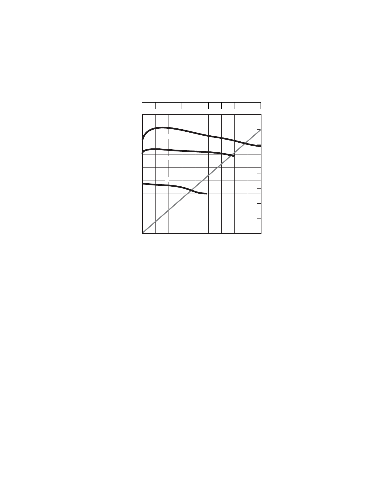
Viscount II 460 Pumps
Performance Charts
Viscount II 460 - MR4Ball - 2000cc
Performance @ 600 1050 1200 PSIG
CYCLES PER MIN.
450 (3.1, 31)
400 (2.8, 28)
350 (2.4, 24)
300 (2.1, 21)
250 (1.7, 17)
200 (1.4, 14)
150 (1.0, 10)
100 (0.7, 7)
FLUID PRESSURE, psi (MPa, bar)
Key:
A High PSIG
B Mid PSIG
C Low PSIG
50 (0.3, 3)
0 (0, 0)
048121620
A
B
C
2.0
4.0
6.0
8.0
0.0
(0.0)
(7.0)
(15.0)
(22.5)
FLUID FLOW, gpm (lpm)
(30.0)
10.0
(37.9)
24 28
12.0
(45.4)
14.0
(53.0)
32
16.0
(60.6)
36
18.0
(68.1)
8
7
6
5
4
OIL FLOW (gpm)
3
2
1
0
311211L 29
Page 30

Graco Standard Warranty
Graco warrants all equipment referenced in this document which is manufactured by Graco and bearing its name to be free from defects in
material and workmanship on the date of sale to the original purchaser for use. With the exception of any special, extended, or limited warranty
published by Graco, Graco will, for a period of twelve months from the date of sale, repair or replace any part of the equipment determined by
Graco to be defective. This warranty applies only when the equipment is installed, operated and maintained in accordance with Graco’s written
recommendations.
This warranty does not cover, and Graco shall not be liable for general wear and tear, or any malfunction, damage or wear caused by faulty
installation, misapplication, abrasion, corrosion, inadequate or improper maintenance, negligence, accident, tampering, or substitution of
non-Graco component parts. Nor shall Graco be liable for malfunction, damage or wear caused by the incompatibility of Graco equipment with
structures, accessories, equipment or materials not supplied by Graco, or the improper design, manufacture, installation, operation or
maintenance of structures, accessories, equipment or materials not supplied by Graco.
This warranty is conditioned upon the prepaid return of the equipment claimed to be defective to an authorized Graco distributor for verification of
the claimed defect. If the claimed defect is verified, Graco will repair or replace free of charge any defective parts. The equipment will be returned
to the original purchaser transportation prepaid. If inspection of the equipment does not disclose any defect in material or workmanship, repairs will
be made at a reasonable charge, which charges may include the costs of parts, labor, and transportation.
THIS WARRANTY IS EXCLUSIVE, AND IS IN LIEU OF ANY OTHER WARRANTIES, EXPRESS OR IMPLIED, INCLUDING BUT NOT LIMITED
TO WARRANTY OF MERCHANTABILITY OR WARRANTY OF FITNESS FOR A PARTICULAR PURPOSE.
Graco’s sole obligation and buyer’s sole remedy for any breach of warranty shall be as set forth above. The buyer agrees that no other remedy
(including, but not limited to, incidental or consequential damages for lost profits, lost sales, injury to person or property, or any other incidental or
consequential loss) shall be available. Any action for breach of warranty must be brought within two (2) years of the date of sale.
GRACO MAKES NO WARRANTY, AND DISCLAIMS ALL IMPLIED WARRANTIES OF MERCHANTABILITY AND FITNESS FOR A
PARTICULAR PURPOSE, IN CONNECTION WITH ACCESSORIES, EQUIPMENT, MATERIALS OR COMPONENTS SOLD BUT NOT
MANUFACTURED BY GRACO. These items sold, but not manufactured by Graco (such as electric motors, switches, hose, etc.), are subject to
the warranty, if any, of their manufacturer. Graco will provide purchaser with reasonable assistance in making any claim for breach of these
warranties.
In no event will Graco be liable for indirect, incidental, special or consequential damages resulting from Graco supplying equipment hereunder, or
the furnishing, performance, or use of any products or other goods sold hereto, whether due to a breach of contract, breach of warranty, the
negligence of Graco, or otherwise.
FOR GRACO CANADA CUSTOMERS
The Parties acknowledge that they have required that the present document, as well as all documents, notices and legal proceedings entered into,
given or instituted pursuant hereto or relating directly or indirectly hereto, be drawn up in English. Les parties reconnaissent avoir convenu que la
rédaction du présente document sera en Anglais, ainsi que tous documents, avis et procédures judiciaires exécutés, donnés ou intentés, à la suite
de ou en rapport, directement ou indirectement, avec les procédures concernées.
Graco Information
For the latest information about Graco products, visit www.graco.com.
TO PLACE AN ORDER, contact your Graco distributor or call to identify the nearest distributor.
Phone: 612-623-6921 or Toll Free: 1-800-328-0211 Fax: 612-378-3505
All written and visual data contained in this document reflects the latest product information available at the time of publication.
Graco reserves the right to make changes at any time without notice.
This manual contains English. MM 311211
Graco Headquarters: Minneapolis
International Offices: Belgium, China, Japan, Korea
GRACO INC. P.O. BOX 1441 MINNEAPOLIS, MN 55440-1441
Copyright 2006, Graco Inc. is registered to ISO 9001
www.graco.com
Revised 3/2009
 Loading...