

Page 1
Instructions - Parts List
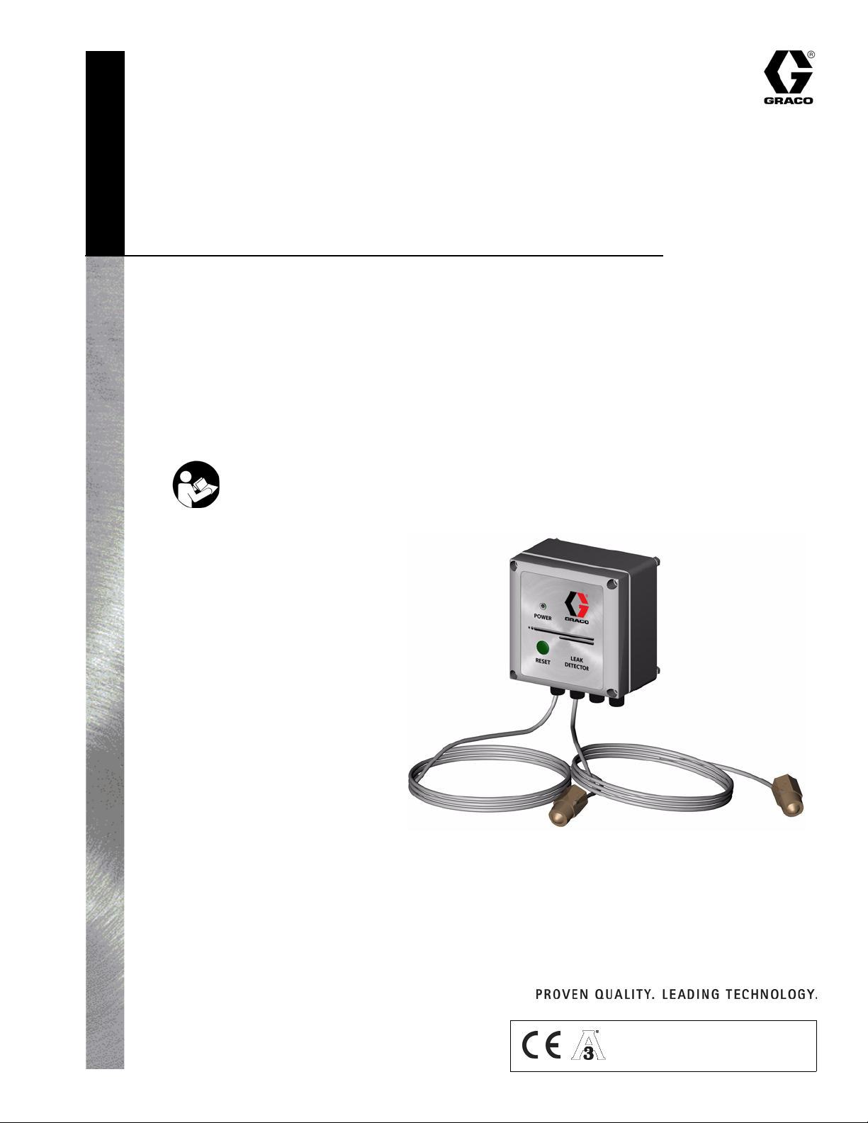
Leak Detection
System
For detecting leaks in your diaphragm pump system.
Not for use in explosive atmospheres.
Part No. 234576
120 psi (0.8 MPa, 8 bar) Maximum Air Input Pressure
Important Safety Instructions
Read all warnings and instructions in this manual.
Save these instructions.
See page 2 for Table of Contents.
311200A
Graco Inc. P.O. Box 1441 Minneapolis, MN 55440-1441
Copyright 2005, Graco Inc. is registered to I.S. EN ISO 9001
TI6850A
Page 2

Contents
Warnings
Warnings . . . . . . . . . . . . . . . . . . . . . . . . . . . . . . . . . 2
Overview . . . . . . . . . . . . . . . . . . . . . . . . . . . . . . . . . . 3
Installation . . . . . . . . . . . . . . . . . . . . . . . . . . . . . . . . 5
Operation . . . . . . . . . . . . . . . . . . . . . . . . . . . . . . . . . 7
Maintenance . . . . . . . . . . . . . . . . . . . . . . . . . . . . . . . 7
Troubleshooting . . . . . . . . . . . . . . . . . . . . . . . . . . . . 8
Technical Data . . . . . . . . . . . . . . . . . . . . . . . . . . . . . 9
Graco Standard Warranty . . . . . . . . . . . . . . . . . . . 10
Graco Information . . . . . . . . . . . . . . . . . . . . . . . . . 10
Warnings
The following general warnings are for the safe setup, use, grounding, maintenance and repair of this equipment. The
exclamation point symbols alert you to general warnings and the hazard symbols refer to procedure-specific risks.
Refer back to these warnings. Additional product-specific warnings may be found throughout the body of this manual
where applicable.
WARNING
ELECTRIC SHOCK HAZARD
Improper grounding, setup, or usage of the system can cause electric shock.
• Turn off and disconnect power at main switch before disconnecting any cables and before servicing
equipment.
• Connect only to grounded power source.
• All electrical wiring must be done by a qualified electrician and comply with all local codes and regulations.
• Do not expose to rain. Store indoors.
EQUIPMENT MISUSE HAZARD
Misuse can cause death or serious injury.
• Do not exceed the maximum working pressure or temperature rating of the lowest rated system
component. See Technical Data in all equipment manuals. For complete information about your
material, request MSDS from distributor or retailer.
• Use fluids and solvents that are compatible with equipment wetted parts. See Technical Data in all
equipment manuals. Read fluid and solvent manufacturer’s warnings.
• Check equipment daily. Repair or replace worn or damaged parts immediately with genuine Graco
replacement parts only.
• Do not alter or modify equipment.
• For professional use only.
• Use equipment only for its intended purpose. Call your Graco distributor for information.
• Route hoses and cables away from traffic areas, sharp edges, moving parts, and hot surfaces.
• Do not kink or over bend hoses or use hoses to pull equipment.
• Comply with all applicable safety regulations.
• Keep children and animals away from work area.
• Do not operate the unit when fatigued or under the influence of drugs or alcohol.
PERSONAL PROTECTIVE EQUIPMENT
You must wear appropriate protective equipment when operating, servicing, or when in the operating
area of the equipment to help protect you from serious injury, including eye injury, inhalation of toxic
fumes, burns, and hearing loss. This equipment includes but is not limited to:
• Protective eyewear
• Clothing and respirator as recommended by the fluid and solvent manufacturer
•Gloves
• Hearing protection
2 311200A
Page 3

Overview
Overview
Usage
The leak detector monitors air operated double diaphragm pumps for diaphragm rupture or other leaks that
may contaminate the fluid being pumped. The system is
made up of a main control box and two liquid detection
sensors. The sensors are screwed into the air side of
each diaphragm on the pump. When liquid is sensed by
either one of the sensors, an alarm will sound, indicating
a diaphragm rupture has occurred. The control box also
has the ability to control an external device such as an
alarm, light, or an air solenoid via an onboard relay.
During normal operation, the LED indicators on the control box and each sensor will flash once per second,
indicating proper operation. If a system fault or a leak is
detected, an alarm will sound and the LED on the control box will blink three times per second. See table,
page 8.
Component Identification and
Description
Before you install the system, you should be familiar
with the parts discussed in the following paragraphs.
Sensors
The sensors are mounted on the pump to detect liquid
on the air side of the diaphragm. See F
F
IG. 5.
IG. 1, FIG. 2, and
Having both conductive and optical sensors allows the
sensor to detect as many liquids as possible. When both
sensors are in air, both lights (blue and yellow) flash
once per second.
When the sensor is immersed in a conductive liquid, the
blue LED will stop flashing. When the sensor is
immersed in a liquid compatible with the optical sensor
the yellow LED will stop flashing.
Control Box
The control box powers and monitors the sensors and
sound the alarm when a leak is detected.
The control box powers and reads the sensors every
second. If the sensors detect liquid, the control box will
alarm and set it’s fault relay.
Relay
The relay has two sets of contacts that can be used to
indicate an error by turning off a valve, lighting a light,
etc. The contacts are located at J4 on the circuit board.
See F
IG. 6.
There are two separate sets of Common, NO/NC contacts labeled CRS.
• C (Common)
• R is Reset, which is connected to Common during
normal operation. (NO)
The sensors use two methods of detection: optical and
conductive.
Sensors Definition
Conductive The two metal pins on the sensors.
Controls the blue light and its signal
is the white wire.
Optical The plastic dome in the center of the
sensor. Controls the yellow light and
its signal is the green wire.
311200A 3
• S is Set, which is connected to Common when an
error is detected. (NC)
For example, if an air valve was held open during normal
operation, the power to the valve would enter at C and
exit at R. During normal operation C and R are connected and would open if liquid were detected by a sensor. This would stop the pump. Power must be
maintained to the control box for the pump to operate.
When the control box loses power it will set the relay.
Both sets of CRS contacts are floating contacts and are
electrically isolated from each other and the electronics
on the control board. They do not supply power and
should be used as a switch only.
Page 4

FIG. 1
Overview
Control Box
Sensors
(234789)
TI6850A
4 311200A
Page 5

Installation
Installation
1. Mount the leak detector box in a convenient location.
2. Remove plugs from the pump, if plugs are present.
3. Remove the sensor covers. Connect the leak detector to the pump by screwing the sensors into the
pump. Use thread sealant, as needed. See F
F
IG. 2
IG. 5.
4. Route the sensor wires into the leak detector box
through the fittings at the bottom of the box. Tighten
the fittings.
6. The control box can be powered by 230 VAC, 110
VAC, or 24 VDC.
AC power is connected to J6 on the circuit board. The
ground connection is the pin between the pins N and
110. See F
IG. 6.
a. To operate on 230 VAC, connect between pins
marked N and 220.
b. To operate from 110 VAC, connect between pins
marked N and 110.
c. To operate from 24 VDC, connect to J1. J1 is
marked for positive and negative polarity. Disconnect any power to the AC connector J6 if the
system is to be powered by 24 VDC. See F
IG. 6.
IG. 3
F
5. Attach the lead wires into the terminal strip. See F
4.
The wires must be attached in the following order
from left to right: black, red, white, green.
Green
Black
Red
White
IG.
Connect the leak detector to a 24 VDC power source
OR a 110 VAC or 230 VAC power source. Do not connect to both.
7. Connect an external ACPRH, air valve, etc. to the
internal relay (CRS), if desired, using J4. See F
IG. 6.
• C (Common)
• R is Reset, which is connected to Common dur-
ing normal operation. (NO)
• S is Set, which is connected to Common when
an error is detected. (NC)
F
IG. 4
311200A 5
Page 6

Typical Installation
Sensors
TI6851A
F
IG. 5
Terminal Connections
Installation
Relay
J4 (Relay)
FIG. 6
Grounding
J6 (Line Voltage)J5 (Sensor 2) J1 (24 VDC)J3 (Sensor 1)
1. Follow the instructions in your pump manual to
ground the Graco diaphragm pump system and
check its electrical grounding continuity.
2. When the Leak Detector is powered by 230 VAC or
110 VAC, ground the Leak Detector by connecting
the ground wire to terminal G on terminal J6. See
F
IG. 6.
6 311200A
Page 7

Operation
Operation
Leak Detector Operation
During normal operation, the LED on the leak detector
control box and the sensors will flash once per second.
LED
Reset Button
F
IG. 7
If an error or a diaphragm rupture occurs, the LED and
sensors will flash three times per second and the alarm
will sound. The relay will trip and change state. To stop
the alarm, press the reset button or remove power for 30
seconds. See F
IG. 7.
TI6850A
Maintenance
Clean Sensors
Clean the sensors whenever the pump is disassembled
for cleaning or inspection.
311200A 7
Page 8

Troubleshooting
Problem Cause Solution
Troubleshooting
Light flashes 3/sec and
alarm sounds 1/sec.
Light flashes 3/sec and
alarm sounds 3/sec.
Light flashes 3/sec and
alarm sounds 8/sec.
Relay is set and light
flashes 3/sec until
reserve power is gone.
Sensor has detected liquid. Determine which sensor has detected the liquid.
Inspect the diaphragm on the side which liquid has
been detected.
Replace diaphragm as necessary.
To assure proper sensor operation, clean and dry the
sensor head and the air side of the diaphragm pump.
One of the sensors is
unplugged or has failed.
The reset button is stuck in
the down position.
Loss of power to the leak
detection system.
Remove the cover from the leak detector control box.
Inspect the sensor connection for proper contacts and
connections.
If the problem persists, replace the sensor(s) as
required.
Remove any obstruction possibly depressing the reset
button.
If no obstruction exists, remove the cover and inspect
the reset button for anything holding it in the down
position.
Once main power is restored, the alarm will clear and
the system will resume normal operation. If the control
box relay is wired to the air supply to the pump, the
control box must be powered for the pump to work.
8 311200A
Page 9

Technical Data
Input voltage range . . . . . . . . . . . . . . . . . . . . . . . . . . . . . . 12-28 VDC
100-130 VAC, 50/60 Hz
190-260 VAC, 50/60 Hz
Maximum power consumption . . . . . . . . . . . . . . . . . . . . . 3 W
Relay contact rating, 230 VAC . . . . . . . . . . . . . . . . . . . . . 60 W, 62.5 VA
Maximum sensor pressure . . . . . . . . . . . . . . . . . . . . . . . . 200 psi (1.4 MPa, 14 bar)
Operating temperature range . . . . . . . . . . . . . . . . . . . . . . 0-104°F (-18-40°C)
Maximum sensor line length . . . . . . . . . . . . . . . . . . . . . . . 2 ft (.6 m)
EMC compatibility . . . . . . . . . . . . . . . . . . . . . . . . . . . . . . . CE compliant
Type of liquids that can be detected: water, oil, or any liquid compatible with polysulphone.
Technical Data
311200A 9
Page 10

Graco Standard Warranty
Graco warrants all equipment referenced in this document which is manufactured by Graco and bearing its name to be free from defects in
material and workmanship on the date of sale to the original purchaser for use. With the exception of any special, extended, or limited warranty
published by Graco, Graco will, for a period of twelve months from the date of sale, repair or replace any part of the equipment determined by
Graco to be defective. This warranty applies only when the equipment is installed, operated and maintained in accordance with Graco’s written
recommendations.
This warranty does not cover, and Graco shall not be liable for general wear and tear, or any malfunction, damage or wear caused by faulty
installation, misapplication, abrasion, corrosion, inadequate or improper maintenance, negligence, accident, tampering, or substitution of
non-Graco component parts. Nor shall Graco be liable for malfunction, damage or wear caused by the incompatibility of Graco equipment with
structures, accessories, equipment or materials not supplied by Graco, or the improper design, manufacture, installation, operation or
maintenance of structures, accessories, equipment or materials not supplied by Graco.
This warranty is conditioned upon the prepaid return of the equipment claimed to be defective to an authorized Graco distributor for verification of
the claimed defect. If the claimed defect is verified, Graco will repair or replace free of charge any defective par ts. The equipment will be returned
to the original purchaser transportation prepaid. If inspection of the equipment does not disclose any defect in material or workmanship, repairs will
be made at a reasonable charge, which charges may include the costs of parts, labor, and transportation.
THIS WARRANTY IS EXCLUSIVE, AND IS IN LIEU OF ANY OTHER WARRANTIES, EXPRESS OR IMPLIED, INCLUDING BUT NOT LIMITED
TO WARRANTY OF MERCHANTABILITY OR WARRANTY OF FITNESS FOR A PARTICULAR PURPOSE.
Graco’s sole obligation and buyer’s sole remedy for any breach of warranty shall be as set forth above. The buyer agrees that no other remedy
(including, but not limited to, incidental or consequential damages for lost profits, lost sales, injury to person or property, or any other incidental or
consequential loss) shall be available. Any action for breach of warranty must be brought within two (2) years of the date of sale.
GRACO MAKES NO WARRANTY, AND DISCLAIMS ALL IMPLIED WARRANTIES OF MERCHANTABILITY AND FITNESS FOR A
PARTICULAR PURPOSE, IN CONNECTION WITH ACCESSORIES, EQUIPMENT, MATERIALS OR COMPONENTS SOLD BUT NOT
MANUFACTURED BY GRACO. These items sold, but not manufactured by Graco (such as electric motors, switches, hose, etc.), are subject to
the warranty, if any, of their manufacturer. Graco will provide purchaser with reasonable assistance in making any claim for breach of these
warranties.
In no event will Graco be liable for indirect, incidental, special or consequential damages resulting from Graco supplying equipment hereunder, or
the furnishing, performance, or use of any products or other goods sold hereto, whether due to a breach of contract, breach of warranty, the
negligence of Graco, or otherwise.
FOR GRACO CANADA CUSTOMERS
The Parties acknowledge that they have required that the present document, as well as all documents, notices and legal proceedings entered into,
given or instituted pursuant hereto or relating directly or indirectly hereto, be drawn up in English. Les parties reconnaissent avoir convenu que la
rédaction du présente document sera en Anglais, ainsi que tous documents, avis et procédures judiciaires exécutés, donnés ou intentés, à la suite
de ou en rapport, directement ou indirectement, avec les procédures concernées.
Graco Information
TO PLACE AN ORDER, contact your Graco distributor or call to identify the nearest distributor.
Phone: 612-623-6921 or Toll Free: 1-800-328-0211 Fax: 612-378-3505
All written and visual data contained in this document reflects the latest product information available at the time of publication.
Graco reserves the right to make changes at any time without notice.
MM 311200
Graco Headquarters: Minneapolis
International Offices: Belgium, China, Japan, Korea
GRACO INC. P.O. BOX 1441 MINNEAPOLIS, MN 55440-1441
www.graco.com
Printed in USA 311200A
6/2005
 Loading...