

Page 1
Instructions-Parts List
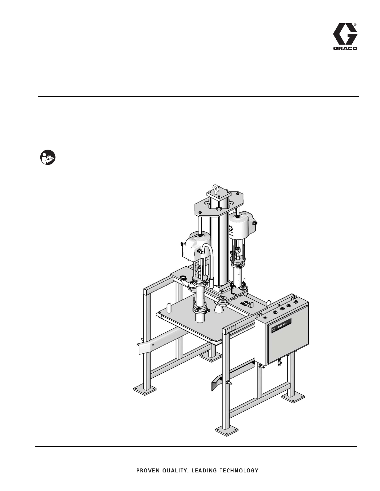
Model BESE1A Shown
ti16236a
™
SaniForce
311163ZAC
Bin Evacuation System
For use with 300 gallon (1135 liter) bags in bin containers. For professional use only.
Not approved to European Explosive Atmosphere requirements.
See page 3 for model information, including maximum working pressure and approvals.
Important Safety Instructions
Read all warnings and instructions in this
manual. Save these instructions.
EN
Page 2

Contents
Models . . . . . . . . . . . . . . . . . . . . . . . . . . . . . . . . . . . . . . . . .3
Warnings . . . . . . . . . . . . . . . . . . . . . . . . . . . . . . . . . . . . . . .5
Overview . . . . . . . . . . . . . . . . . . . . . . . . . . . . . . . . . . . . . . .7
Operation Overview. . . . . . . . . . . . . . . . . . . . . . . . . . . . 7
Basic Operation of SaniForce BES . . . . . . . . . . . . . . . . 7
System Components (Manual Control) . . . . . . . . . . . . . 8
System Components (Electronic Control) . . . . . . . . . . . 9
Before Installing . . . . . . . . . . . . . . . . . . . . . . . . . . . . . . . . 10
Installation . . . . . . . . . . . . . . . . . . . . . . . . . . . . . . . . . . . .11
Anchoring Frame . . . . . . . . . . . . . . . . . . . . . . . . . . . . 11
Installing Air Cylinder . . . . . . . . . . . . . . . . . . . . . . . . . 11
Connecting Pump Output Hoses . . . . . . . . . . . . . . . .13
Grounding . . . . . . . . . . . . . . . . . . . . . . . . . . . . . . . . . .14
Checking Resistance . . . . . . . . . . . . . . . . . . . . . . . . . 14
Prepare the Operator . . . . . . . . . . . . . . . . . . . . . . . . .14
Manual Stop (all models) . . . . . . . . . . . . . . . . . . . . . . . . . 15
Engaging . . . . . . . . . . . . . . . . . . . . . . . . . . . . . . . . . . . 15
Lockout . . . . . . . . . . . . . . . . . . . . . . . . . . . . . . . . . . . . 15
Disengaging. . . . . . . . . . . . . . . . . . . . . . . . . . . . . . . . . 15
Manual Control System . . . . . . . . . . . . . . . . . . . . . . . . . . 16
Part No. 15E523 Manual Control . . . . . . . . . . . . . . . . 16
Pressure Relief Procedure . . . . . . . . . . . . . . . . . . . . . 17
Initial Startup . . . . . . . . . . . . . . . . . . . . . . . . . . . . . . . . 17
Setting Air Pressures . . . . . . . . . . . . . . . . . . . . . . . . . 17
Standard Operation . . . . . . . . . . . . . . . . . . . . . . . . . . . 18
System Shutdown . . . . . . . . . . . . . . . . . . . . . . . . . . . .18
Electronic Control System . . . . . . . . . . . . . . . . . . . . . . . 19
Connecting Pneumatic Control Panel Air Lines . . . . . 19
Installing Electronic Control Panel . . . . . . . . . . . . . . . 20
Part No. 15H145 and 15J902
Electronic Control Panel . . . . . . . . . . . . . . . . . . .21
Proximity Switch . . . . . . . . . . . . . . . . . . . . . . . . . . . . . 22
Setting Air Pressures . . . . . . . . . . . . . . . . . . . . . . . . . 23
Pressure Relief Procedure . . . . . . . . . . . . . . . . . . . . . 24
Initial Startup . . . . . . . . . . . . . . . . . . . . . . . . . . . . . . . . 24
Standard Operation . . . . . . . . . . . . . . . . . . . . . . . . . . . 26
System Shutdown . . . . . . . . . . . . . . . . . . . . . . . . . . . .27
Maintenance . . . . . . . . . . . . . . . . . . . . . . . . . . . . . . . . . . .28
Air Motor Icing . . . . . . . . . . . . . . . . . . . . . . . . . . . . . . . 28
Preventive Maintenance. . . . . . . . . . . . . . . . . . . . . . . . 28
Flushing the System . . . . . . . . . . . . . . . . . . . . . . . . . . 28
Cleaning Pumps . . . . . . . . . . . . . . . . . . . . . . . . . . . . .28
Cleaning Ram Plate and Seal . . . . . . . . . . . . . . . . . . .29
Troubleshooting . . . . . . . . . . . . . . . . . . . . . . . . . . . . . . . . 30
Service . . . . . . . . . . . . . . . . . . . . . . . . . . . . . . . . . . . . . . . 31
Before Servicing . . . . . . . . . . . . . . . . . . . . . . . . . . . . .31
Replacing Cylinder Bearing (All Models) . . . . . . . . . . 31
Replacing Ram Plate Seal or Corner Seals
(All Models) . . . . . . . . . . . . . . . . . . . . . . . . . . . . . 32
Replacing Proximity Switch
(Electronic Control Models Only) . . . . . . . . . . . . . 33
Electronic Control Panel Service
(Electronic Control Models Only) . . . . . . . . . . . . . 33
SaniForce BES Pump Matrices . . . . . . . . . . . . . . . . . . . . 34
3150 AODD Pumps . . . . . . . . . . . . . . . . . . . . . . . . . . 34
Available Configurations* . . . . . . . . . . . . . . . . . . . . . . 34
Piston Pumps . . . . . . . . . . . . . . . . . . . . . . . . . . . . . . . 35
Available Configurations* . . . . . . . . . . . . . . . . . . . . . . 35
SaniForce BES Common Parts . . . . . . . . . . . . . . . . . . . . 36
SaniForce BES Common Parts (BESA7A shown) . . . 37
Pump Modules . . . . . . . . . . . . . . . . . . . . . . . . . . . . . . . . . 38
Models 24G560 and 24G968, 5:1 SaniForce
Double Ball Pump Module (2 Pumps) . . . . . . . . . 38
Model 24P829, 5:1 SaniForce Priming Piston
Pump Module (2 Pumps) . . . . . . . . . . . . . . . . . . . 39
Model 24G561, 5:1 SaniForce Double Ball
Pump Module (4 Pumps) . . . . . . . . . . . . . . . . . . . 40
Model 24P815, 6:1 SaniForce Priming Piston
Pump Module (2 Pumps) . . . . . . . . . . . . . . . . . . . 41
Model 249488, 24E441, and 24C125 3150 SaniForce
Ball Check Pump Module (2 Pumps) . . . . . . . . . . 42
Model 249489 3150 SaniForce Flapper Check Pump
Module (2 Pumps) . . . . . . . . . . . . . . . . . . . . . . . . 43
Model 24G564 and 24G969 12:1 SaniForce Priming
Piston Pump Module (2 Pumps). . . . . . . . . . . . . . 44
Part No. 24G566 and 24G970 12:1 SaniForce Priming
Piston Pump Module (4 Pumps) . . . . . . . . . . . . . 45
Inflatable Seal, Plate, Frames, and Controls . . . . . . . . . 46
Part No. 15E523, 2 Pump Manual Control Panel . . . . 47
Part No. 15E523, 2 Pump Manual Control Panel,
Pneumatic Diagram . . . . . . . . . . . . . . . . . . . . . . . 48
Part No. 15M343, 4 Pump Manual Control Panel . . . . 49
Part No. 15M343, 4 Pump Manual Control Panel,
Pneumatic Diagram . . . . . . . . . . . . . . . . . . . . . . . 50
Part No. 949949, 2 Pump Pneumatic Control Panel . . 51
Part No. 949949, 2 Pump Pneumatic Control Panel . . 52
Part No. 570193, 4 Pump Pneumatic Control Panel . . 53
Part No. 570193, 4 Pump Pneumatic Control Panel . . 54
Common Parts for 570193 and 949949 Pneumatic
Control Panels . . . . . . . . . . . . . . . . . . . . . . . . . . . 55
Common Parts for 570193 and 949949 Pneumatic
Control Panels . . . . . . . . . . . . . . . . . . . . . . . . . . . 56
Part No. 949949 Pneumatic Control Panel,
Pneumatic Diagram . . . . . . . . . . . . . . . . . . . . . . . 57
Part No. 570193 Pneumatic Control Panel,
Pneumatic Diagram . . . . . . . . . . . . . . . . . . . . . . . 58
Dimensions . . . . . . . . . . . . . . . . . . . . . . . . . . . . . . . . . . . 60
Technical Data . . . . . . . . . . . . . . . . . . . . . . . . . . . . . . . . . 62
BES3xx, BES4xx, and BES8xx . . . . . . . . . . . . . . . . . 62
BESAxx, BESBxx, BESCxx, BESDxx, BESExx, and
BESFxx . . . . . . . . . . . . . . . . . . . . . . . . . . . . . . . . 63
Graco Standard Warranty . . . . . . . . . . . . . . . . . . . . . . . . 64
Graco Information . . . . . . . . . . . . . . . . . . . . . . . . . . . . . . 64
2 311163ZAC
Page 3
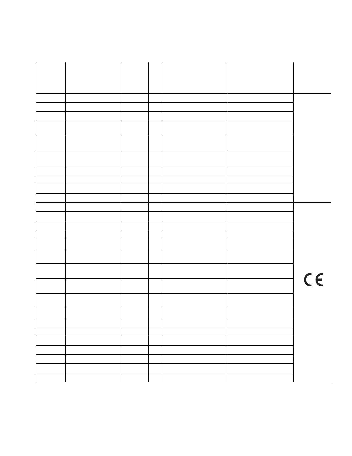
Models
Maximum Working
Fluid Pressure,
BES
Part No.,
BESA7A, 410 (2.8, 28.3) 24G742 2 5:1 SaniForce Pump Electronic, Micrologix (2)
BESA7F 410 (2.8, 28.3) 24G742 2 5:1 SaniForce Pump Electronic Contrologix (2)
BESB7B 410 (2.8, 28.3) 24G742 4 5:1 SaniForce Pump Electronic, Micrologix (4)
BES3A1 120 (0.84, 8.4) 248273 2
BES3P1 120 (0.84, 8.4) 248273 2
BES4A1 120 (0.84, 8.4) 248274 2
BESE1A 1450 (10.1, 100.4) 24F625 2 12:1 SaniForce Pump Electronic, Micrologix (2)
BESF6B 1450 (10.1, 100.4) 24F625 4 12:1 SaniForce Pump Electronic, Micrologix (4)
BESF7B 1450 (10.1, 100.4) 24F625 4 12:1 SaniForce Pump Electronic, Micrologix (4)
BESF9B 1450 (10.1, 100.4) 24F625 4 12:1 SaniForce Pump Electronic, Micrologix (4)
BESA4C 410 (2.8, 28.3) 24G742 2 5:1 SaniForce Pump Manual (2)
BESA7C 410 (2.8, 28.3) 24G742 2 5:1 SaniForce Pump Manual (2)
BESAAC 410 (2.8, 28.3) 24G742 2 5:1 SaniForce Pump Manual (2)
BESB7D 410 (2.8, 28.3) 24G742 4 5:1 SaniForce Pump Manual (4)
BESCCC 410 (2.8, 28.3) 24P829 2 5:1 SaniForce Pump Manual (2)
BES3F3 120 (0.84, 8.4) 24E440 2
BES3P3 120 (0.84, 8.4) 248273 2
BES4P3 120 (0.84, 8.4) 248274 2
BES8B3 120 (0.84, 8.4) 24C124 2
BESDBC 650 (4.5, 44.8) 24F942 2 6:1 SaniForce Pump Manual (2)
BESE1C 1450 (10.1, 100.4) 24F625 2 12:1 SaniForce Pump Manual (2)
BESE5C 1450 (10.1, 100.4) 24F625 2 12:1 SaniForce Pump Manual (2)
BESE7C 1450 (10.1, 100.4) 24F625 2 12:1 SaniForce Pump Manual (2)
BESEAC 1450 (10.1, 100.4) 24D658 2 12:1 SaniForce Pump Manual (2)
BESF6D 1450 (10.1, 100.4) 24F625 4 12:1 SaniForce Pump Manual (4)
BESF7D 1450 (10.1, 100.4) 24F625 4 12:1 SaniForce Pump Manual (4)
BESF9D 1450 (10.1, 100.4) 24F625 4 12:1 SaniForce Pump Manual (4)
per pump
psi (MPa, bar)
Pump
Part No.
Qty. Pump Controls Approvals
3150 SaniForce Pump,
Ball Check Electronic, Micrologix (2)
3150 SaniForce Pump,
Ball Check Electronic, Micrologix (2)
3150 SaniForce Pump,
Flapper Check Electronic, Micrologix (2)
3150 SaniForce Pump,
3A Ball Check Manual (2)
3150 SaniForcePump,
Ball Check Manual (2)
3150 SaniForce Pump,
Flapper Check Manual (2)
3150 SaniForce Pump,
3A Ball Check Manual (2)
Models
311163ZAC 3
Page 4

Models
Material Certification
Reference: SaniForce Product Family
Issue Date: September 14, 2011
All fluid contact materials in the SaniForce product family are FDA-Compliant and meet the United States
Code of Federal Regulations (CFR) Title 21, Section 177 or are of a corrosion resistant grade Stainless
Steel. This includes the below product groups:
1. SaniForce 1040, 1590, 2150 Air-Operated Double Diaphragm Pumps
2. SaniForce 1590, 3150 HS Air-0perated Double Diaphragm Pumps
3. SaniForce 1590, 3150 HS 3-A Certified Air-Operated Double Diaphragm Pumps
4. SaniForce 5:1, 6:1 and 12:1 Air-Operated Piston Pumps
5. SaniForce Diaphragm Pump and Piston Pump Drum Unloaders
6. SaniForce Diaphragm Pump and Piston Pump Bin Evacuation Systems
Bradley A. Byron
Quality Manager
Graco Inc.
4 311163ZAC
Page 5
Warnings
Warnings
The following warnings are for the setup, use, grounding, maintenance, and repair of this equipment. The exclamation point symbol alerts you to a general warning and the hazard symbols refer to procedure-specific risks. When
these symbols appear in the body of this manual, refer back to these Warnings. Product-specific hazard symbols and
warnings not covered in this section may appear throughout the body of this manual where applicable.
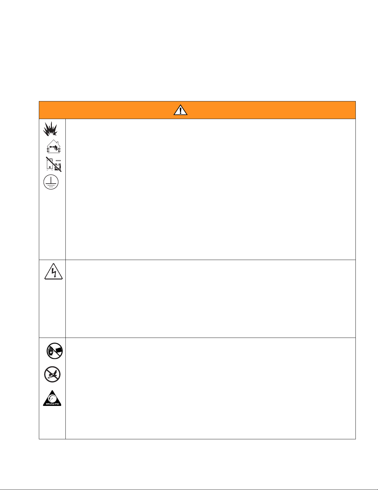
Warning
FIRE AND EXPLOSION HAZARD
Flammable fumes, such as solvent and paint fumes, in work area can ignite or explode. To help prevent
fire and explosion:
• Use equipment only in well ventilated area.
• Eliminate all ignition sources; such as pilot lights, cigarettes, portable electric lamps, and plastic
drop cloths (potential static arc).
• Keep work area free of debris, including solvent, rags and gasoline.
• Do not plug or unplug power cords, or turn power or light switches on or off when flammable fumes
are present.
• Ground all equipment in the work area. See Grounding instructions.
• Use only grounded hoses.
• Hold gun firmly to side of grounded pail when triggering into pail.
• If there is static sparking or you feel a shock, stop operation immediately. Do not use equipment
until you identify and correct the problem.
• Keep a working fire extinguisher in the work area.
ELECTRIC SHOCK HAZARD
This equipment must be grounded. Improper grounding, setup, or usage of the system can cause
electric shock.
• Turn off and disconnect power at main switch before disconnecting any cables and before servicing
equipment.
• Connect only to grounded power source.
• All electrical wiring must be done by a qualified electrician and comply with all local codes and
regulations.
SKIN INJECTION HAZARD
High-pressure fluid from dispensing device, hose leaks, or ruptured components will pierce skin. This
may look like just a cut, but it is a serious injury that can result in amputation. Get immediate surgical
treatment.
• Do not point dispensing device at anyone or at any part of the body.
• Do not put your hand over the fluid outlet.
• Do not stop or deflect leaks with your hand, body, glove, or rag.
+
• Follow the Pressure Relief Procedure when you stop dispensing and before cleaning, checking, or
servicing equipment.
• Tighten all fluid connections before operating the equipment.
• Check hoses and couplings daily. Replace worn or damaged parts immediately.
311163ZAC 5
Page 6
Warnings
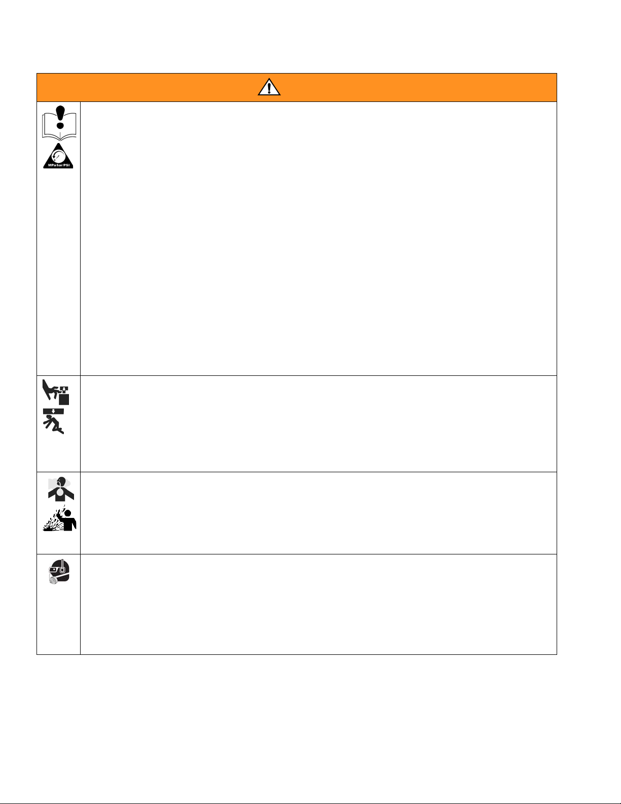
Warning
EQUIPMENT MISUSE HAZARD
Misuse can cause death or serious injury.
• Do not operate the unit when fatigued or under the influence of drugs or alcohol.
• Do not exceed the maximum working pressure or temperature rating of the lowest rated system
component. See Technical Data in all equipment manuals.
• Use fluids and solvents that are compatible with equipment wetted parts. See Technical Data in all
equipment manuals. Read fluid and solvent manufacturer’s warnings. For complete information
about your material, request MSDS from distributor or retailer.
• Do not leave the work area while equipment is energized or under pressure. Turn off all equipment
and follow the Pressure Relief Procedure when equipment is not in use.
• Check equipment daily. Repair or replace worn or damaged parts immediately with genuine
manufacturer’s replacement parts only.
• Do not alter or modify equipment.
• Use equipment only for its intended purpose. Call your distributor for information.
• Route hoses and cables away from traffic areas, sharp edges, moving parts, and hot surfaces.
• Do not kink or over bend hoses or use hoses to pull equipment.
• Keep children and animals away from work area.
• Comply with all applicable safety regulations.
MOVING PARTS HAZARD
Moving parts can pinch, cut or amputate fingers and other body parts.
• Keep clear of moving parts.
• Do not operate equipment with protective guards or covers removed.
• Pressurized equipment can start without warning. Before checking, moving, or servicing equipment,
follow the Pressure Relief Procedure and disconnect all power sources.
TOXIC FLUID OR FUMES HAZARD
Toxic fluids or fumes can cause serious injury or death if splashed in the eyes or on skin, inhaled, or
swallowed.
• Read MSDS’s to know the specific hazards of the fluids you are using.
• Store hazardous fluid in approved containers, and dispose of it according to applicable guidelines.
PERSONAL PROTECTIVE EQUIPMENT
You must wear appropriate protective equipment when operating, servicing, or when in the operating
area of the equipment to help protect you from serious injury, including eye injury, hearing loss,
inhalation of toxic fumes, and burns. This equipment includes but is not limited to:
• Protective eyewear, and hearing protection.
• Respirators, protective clothing, and gloves as recommended by the fluid and solvent manufacturer.
6 311163ZAC
Page 7

Overview
Overview
Operation Overview
The SaniForce BES evacuates fluids from a 300 gallon
(1135 liter) bag in a plywood box, IBC, or collapsible bin.
The SaniForce BES consists of a frame, two or four
Graco pumps, ram plate with an inflatable seal, ram air
cylinder, and a manual or electronic control panel.
Basic Operation of SaniForce
BES
1. The operator places the bin inside the frame.
2. Using the control panel, the operator lowers the ram
plate on top of the material.
3. The operator aligns and centers the bin with the ram
plate.
4. The operator inflates the ram plate seal, applies
down pressure to the ram plate, and turns on the
pumps.
5. The pumps evacuate the material out of the bin.
6. The operator stops the pumps, deflates the seal,
and raises the ram plate out of the bin.
7. The empty bin is removed, another bin is put in
place, and the SaniForce BES is ready to repeat the
process.
311163ZAC 7
Page 8
Overview
E
D
A
F
B
C
AIR IN
PUMP 1
PUMP 2
RAM UP
RAM DOWN
Bottom View of Manual Control Panel (B)
Seal
Ram Up
Ram Down
Pump 2
Pump 1
Air In
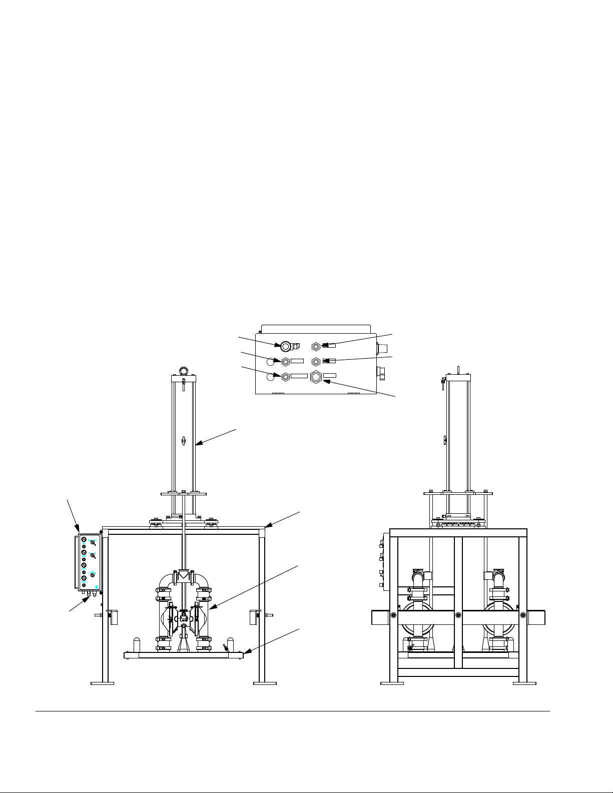
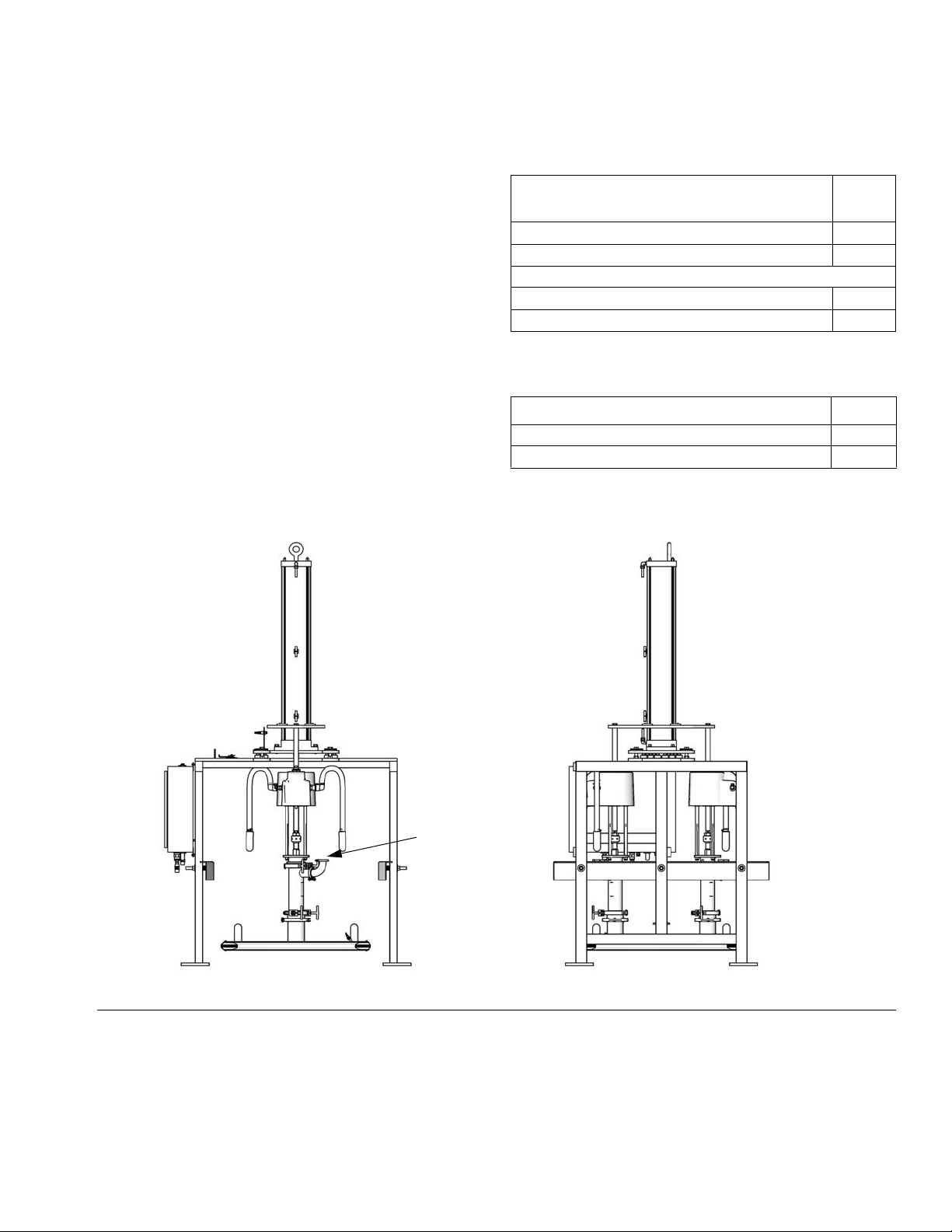
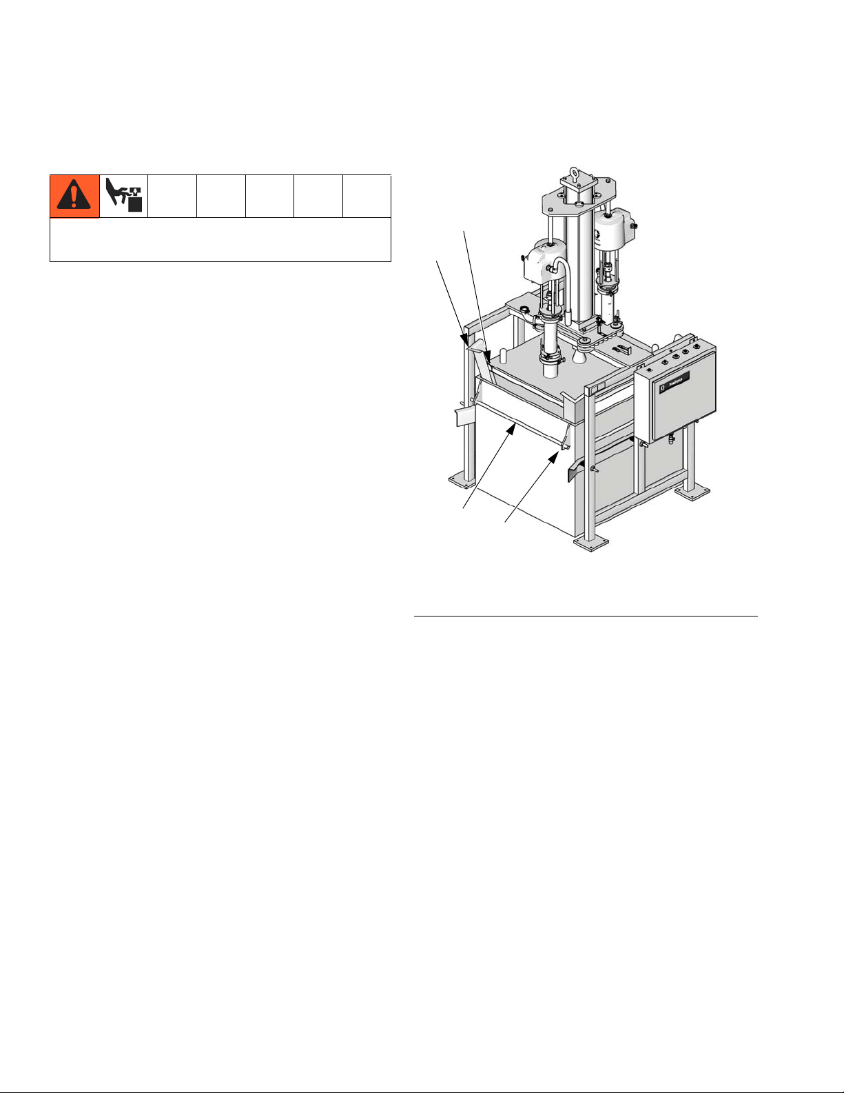
System Components (Manual Control)
See FIG. 1.
A Stainless Steel Frame: supports the cardboard or
collapsible bin.
B Manual Control Panel: contains pneumatic
controls to regulate the air pressure to pump air
motors, ram, and ram plate seal in order to control:
• pump air motor pressure
• pump speed control
• ram up and down pressure
• seal pressure
• turn the pumps on or off
• inflate or deflate the ram plate seal
• raise or lower the ram plate
C Air Shutoff Valve: shuts off air to the pneumatic
control panel (B).
D Sanitary Pumps: pump material from the bin to the
target application.
E Air Cylinder: raises and lowers the pumps and the
ram plate in and out of the material container.
F Ram Plate: applies an even amount of pressure to
the material in the bin. When the ram plate seal is
inflated, it creates a seal. The ram plate presses
down on the material in the bin to assist the pumps
in delivering the material.
FIG. 1: Typical Installation (Manual Control; BES3P3 shown)
8 311163ZAC
Page 9
System Components (Electronic Control)
"%3#/.42/,"%3#/.42/,
0RESET0RESET
0RESET0RESET
0RESET0RESET
023
023
456456
'()
'()
*+,
*+,
3HIFT3HIFT
%SC%SC
%NTER%NTER
3YSTEM3YSTEM
789789
-./-./
!#45!,6!,5%!#45!,6!,5%
4!2'%46!,5%4!2'%46!,5%
02%3%4'!,,/.302%3%4'!,,/.3
0RESET0RESET
0RESET0RESET
0RESET0RESET
1:1: !"#!"# $%&$%&
3TROKE3TROKE
3ET5P3ET5P
+
&ACTOR&ACTOR
5-5-
4OTALIZER4OTALIZER
-ETER-ETER
3CREEN3CREEN
0UMPS0UMPS
%NABLE%NABLE
3,/73,/7
3%!,3%!,
/&&/&& /./.
2!-502!-50
34!2434!24
34/034/0
!54/!54/
05-005-0
-!.-!.&!34&!34 "!4#("!4#(
2!-02%332!-02%33
2!-*/'2!-*/'
%34/0%34/0
0/7%20/7%2
'2!#/'2!#/
R
C
TOP VIEW
F
A
B
E
D
Seal
Ram Up
Ram Down
Pump 2
Pump 1
TI16216a
TI16217a
TI16218a
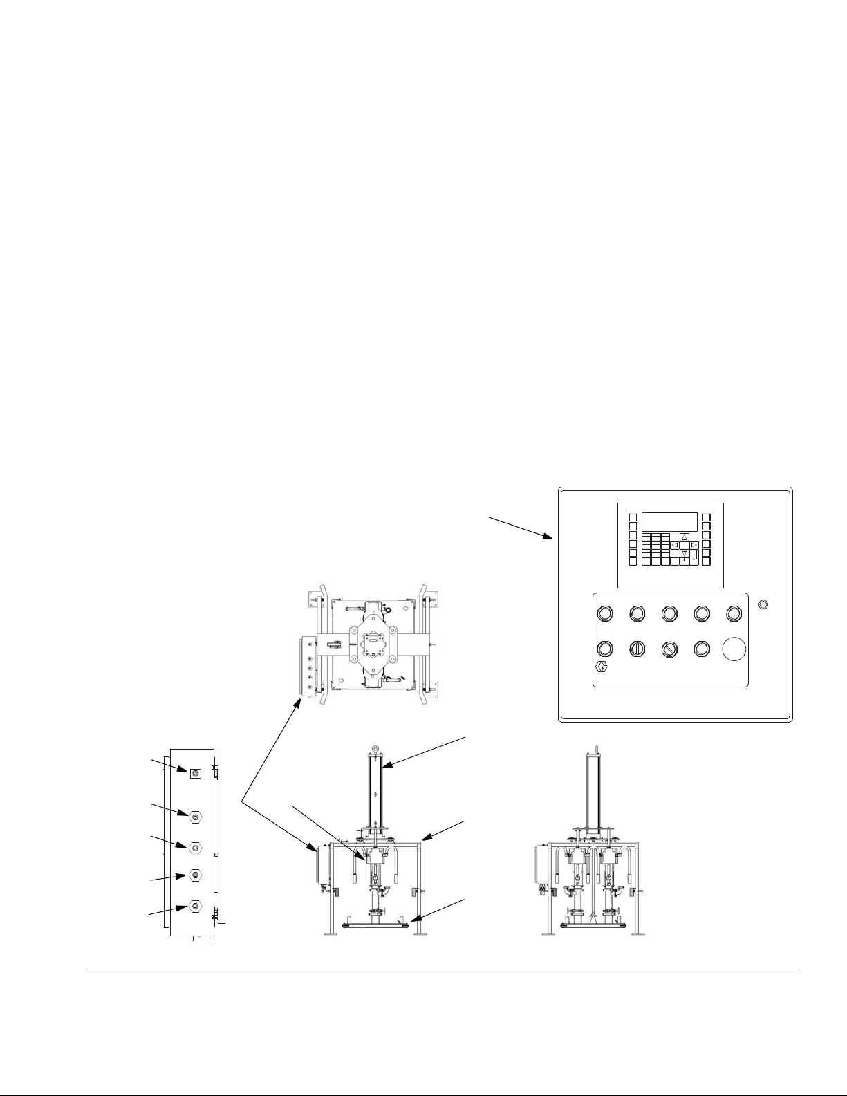
Overview
See FIG. 2.
A Stainless Steel Frame: supports the cardboard or
collapsible bin.
B Pneumatic Control Panel: contains pneumatic
controls to regulate the air pressure to pump air
motors, ram, and ram plate seal in order to control:
• pump air motor pressure
• pump speed control
• ram up and down pressure
• seal pressure
C Electronic Control Panel: is connected to the
pneumatic control panel with the 24 VDC cable
supplied. The panel uses 110 VAC input (20 amp
circuit). If a flow meter is used, it must also be
connected. The electronic control panel sends
signals to:
• turn the pumps on or off
• inflate or deflate the ram plate seal
• raise or lower the ram plate
• turn off the air supply to the ram plate so the
ram can slowly lower into the bin
D Sanitary Pumps: pump material from the bin to the
target application.
E Air Cylinder: raises and lowers the pumps and the
ram plate in and out of the material container.
F Ram Plate: applies an even amount of pressure to
the material in the bin. When the ram plate seal is
inflated, it creates a seal. The ram plate presses
down on the material in the bin to assist the pumps
in delivering the material.
FIG. 2: Typical Installation (Electronic Control; BESA7A shown)
311163ZAC 9
Page 10

Before Installing
Before Installing
Uncrating Equipment
NOTICE
Moving the SaniForce BES off the pallet without following this uncrating procedure will damage equipment.
Uncrate the SaniForce BES as follows:
1. Inspect the crate for shipping damage. Contact the
carrier if damaged.
2. Remove plywood sides and top of crate.
3. Check the contents for loose or damaged parts.
4. Compare the packing slip against items inside the
crate. Immediately call your Graco distributor about
any shortages or damage.
5. Remove the band strap holding the cylinder bin to
the frame.
6. Remove and unpack the air cylinder bin and pumps
(if applicable).
NOTE: See your system component manuals to
become familiar with system components and general
operation.
• Provides easy and safe access to the air supply
shutoff valves and the pneumatic control panel.
Graco recommends a minimum of 3 ft (0.91 m) of
open space in front of the panel.
• Provides enough overhead clearance (11 ft, 3.4 m
recommended) for installing and servicing the air
cylinder and connecting air supply lines to the pneumatic control panel.
• Has a flat, level floor.
Moving Frame to Location
The frame is shipped with several major components
attached and weighs about 2500 lb. (1134 kg). To
avoid injury and equipment damage, follow
instructions below. Never have one person move or
lift the frame.
• Do not remove the frame from the pallet at this time.
• Use a forklift or hand truck and support devices,
such as a hoist, and have an adequate number of
personnel to move the frame to the installation site.
Location
When selecting a location, make sure the location:
• Is close to where the fluid is being delivered to minimize back pressure and maximize flow rate.
• Provides enough room around the equipment for
maintenance.
• Does not interfere with opening the pneumatic control panel door or frame door (on one or both sides).
If the frame is rotated 180°, the frame door will open
from left to right or from right to left.
• Provides enough room on the right and/or left side
of the SaniForce BES to easily load and unload fluid
bins with a forklift or pallet-jack hand truck.
10 311163ZAC
• Avoid jarring or tilting the frame while moving it.
NOTE:
• Ensure there is an adequate compressed air supply.
Refer to air motor/pump manual for your pump air
consumption. About 250-300 scfm at 100 psi (0.7
MPa, 7 bar) is required to operate the pumps at the
maximum rate.
• Have all component manuals available for specific
component requirements.
• Ensure that all hoses are properly sized and pressure rated for the system.
Page 11
Installation
4
602
A
TI3116A
Installation
Anchoring Frame
1. Remove bolts holding the frame (602) to the shipping pallet.
The overall system weighs about 2400-3400 lb.
(1089-1542 kg). To avoid injury and equipment
damage, follow instructions below. Never have one
person move or lift the frame.
2. To lift the system, use the top joists on the frame
with a forklift. Have an adequate number of personnel to lift or move the unit; avoid jarring or tilting it.
3. Remove the pallet and all remaining shipping supports from underneath the frame.
The four base footings of the frame and the bottom of
the bin must be level on the same surface in order for
the SaniForce BES to operate properly. If necessary,
level the SaniForce BES using sanitary metal shims.
Make sure the frame does not wobble.
3. Secure the air cylinder (4) to the frame (602) with
the screws (20) and washers (19). See F
4. Install the air motor mounting plate (402), slipping
plate over the top and down the length of air cylinder
(4).
5. Using tubing (6), connect the cylinder upper air supply line to the upper 1/2 in. elbow (26).
6. Using tubing (6), connect the cylinder lower air supply line to the 1/2 in. lower elbow (26).
IG. 4.
Anchor the four foot pads to the floor. To prevent the
frame from being pushed off the floor, the anchor bolts
must be long enough to withstand the 5027 lb. (22.36
kN) of downward force that the air cylinder can exert.
Use the holes in the four base footings as a guide and
drill holes for 1/2 in. (13 mm) bolts. Bolt the frame to the
floor with anchors.
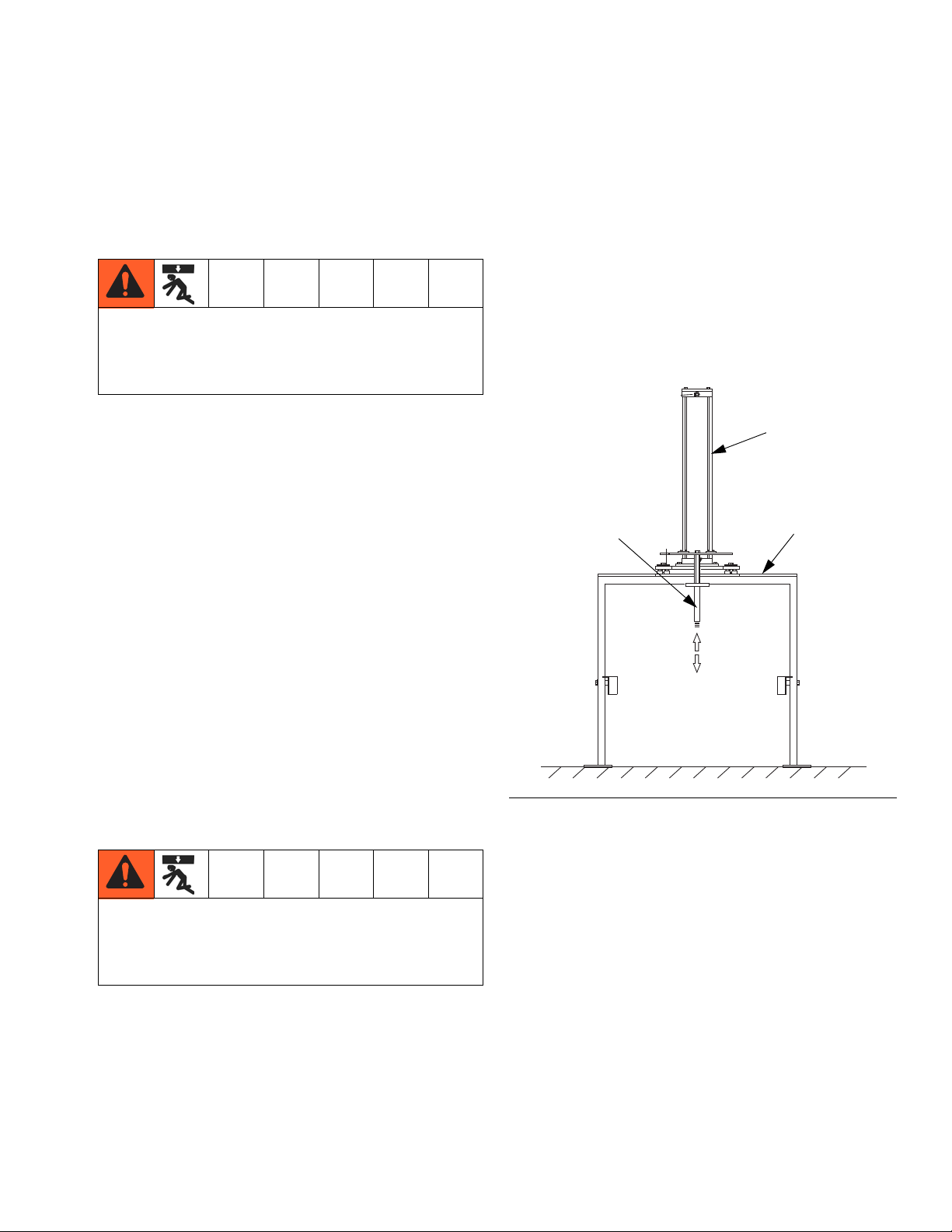
Installing Air Cylinder
The air cylinder weighs about 130 lb. (59 kg). To
avoid injury and equipment damage, follow
instructions below. Never have one person move or
lift the frame.
NOTE: All models do not use the same parts. Refer to
parts lists for your model, pages 35-45.
1. Using a hoist, lift the air cylinder (4) into position on
top of the frame (602). See F
IG. 3.
FIG. 3: Air Cylinder Shaft
7. Loosen but do not remove the screws (18) from the
frame (602).
8. Supply air to main air inlet on pneumatic control box.
9. Remove the two band straps that hold the ram plate
(502) to the shipping pallet. Do not remove the pallet.
10. Apply sanitary grease (36, supplied) to the cylinder
shaft threads to avoid damaging them. Align and
screw the air cylinder shaft (A) into the ram plate
(502). See F
erly, do not force it. Re-check alignment of plate
(502).
IG. 3. If the shaft does not thread prop-
2. Lower the air cylinder shaft (A) through the center
hole in the frame.
311163ZAC 11
Page 12
Installation
405, 411
26
4
602
408,
409,
410
402
502
18
20
19
6
404
R
TI16216a
TI16234a
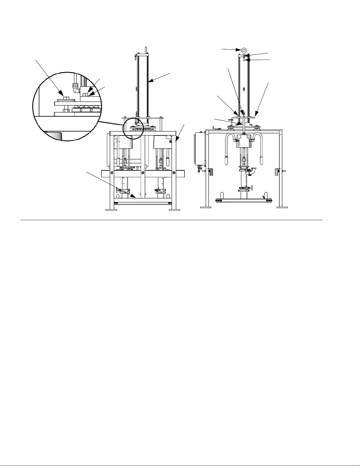
FIG. 4: Air Motor Mounting Plate (BESA7A shown)
11. Uncrate and mount pumps to the ram plate (502),
with outlets facing away from pneumatic control
panel. Secure pumps to plate using the following
gaskets and hardware:
• Part No. BESFxx and BESExx: gasket (415),
screws (406), and washers (407)
• Part No. BESAxx, BESBxx, BESCxx, and
BESDxx: gasket (407), tri-clamp (406)
• Part No. BES3xx and BES4xx: gasket (407),
tri-clamp (406)
• Part No. BES7xx: screws (406), clamps (407),
and gasket (415)
12. For part numbers BES3xx, BES8xx, and BES4xx
install the two connecting rods (404) to the ram
plates. Secure with screws (405) and washers
(411).
13. Install cylinder guide bearings (408) on top of the air
motor mounting plate (402), using screws (409) and
washers (410).
NOTE: The open arch in the cylinder guide bearings
(408) fits around tie rods on the air cylinder (4).
16. On the control panel, switch to the RAM UP position. Raise the ram and set the manual stop latch to
Engage position. See page 15. Remove the pallet
and any other shipping material.
14. Tighten lock nuts (7).
15. Using tubing (6), connect pneumatic control panel to
air motor air inlets.
12 311163ZAC
Page 13
Connecting Pump Output Hoses
406, 407
TI16216a
TI16233a
Installation
NOTE:
• The output hose(s) (supplied by others) should
already be installed, with riggings and supports, and
ready for connection to the 2 in. tri-clamp (412, supplied on some systems). See F
• Make sure the output hose(s) are sized and pressure-rated for the system. Use only electrically conductive hoses with spring guards on both ends.
• The fluid hoses must move freely, without kinking,
when the pumps move up and down.
• The two pump AODD systems do not include a
hose, clamps, or gaskets on the outlet side.
IG. 5.
Two Pump System Includes:
BESAxx, BESBxx, BESCxx, BESExx,
BESFxx
2 in. (51 mm) tri-clamp sanitary clamps (412) 4 or 6
2 in. (51 mm) tri-clamp sanitary gaskets (413) 4 or 6
BESDxx
1.5 in (38 mm) tri-clamp sanitary clamps (412) 4
1.5 in (38 mm) tri-clamp sanitary gaskets (413) 4
Qty
Four Pump System Includes:
Description Qty
2 in. (51 mm) tri-clamp sanitary clamps (412) 8 or 12
2 in. (51 mm) tri-clamp sanitary gaskets (413) 8 or 12
FIG. 5: Connect pump outlet hoses (BESA7A shown)
311163ZAC 13
Page 14
Installation
Y
Z
X
W
X
Y
Z
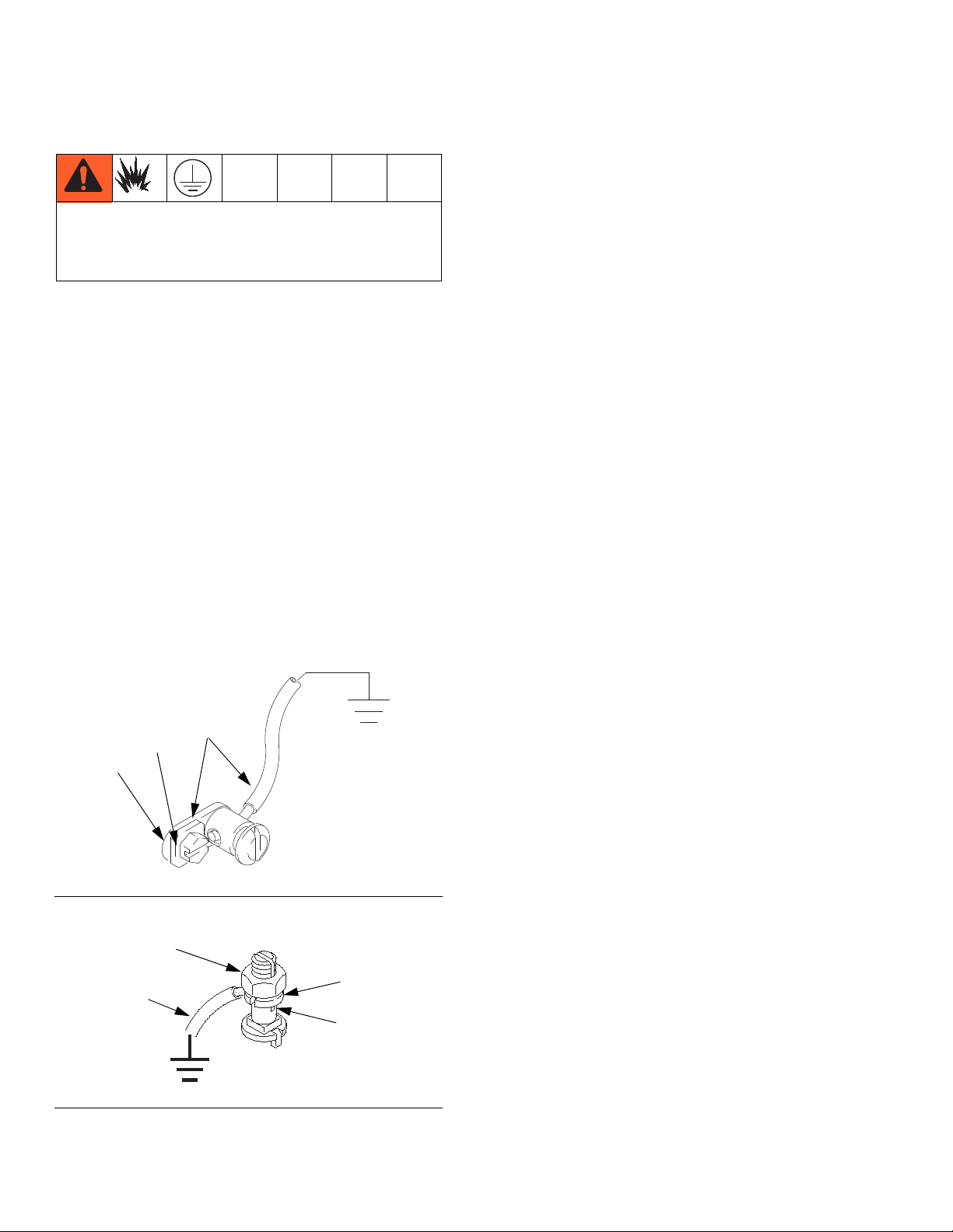
Grounding
The equipment must be grounded. Grounding reduces
the risk of static and electric shock by providing an
escape wire for the electrical current due to static build
up or in the event of a short circuit.
Pump: use the ground wire and clamp (supplied). There
are two styles of grounding connections on pump air
motors.
If you have ground screw shown in F
to order part no. 222011 ground wire, ring terminal, and
clamp assembly (Y). To install 222011, remove the
ground screw (Z) and insert it through the eye of ring terminal (X), then tighten ground screw back into air motor
as shown in F
a true earth ground.
If you have ground screw shown in F
grounding lug locknut (W) and washer (X). Insert one
end of the ground wire (Y) into the slot in lug (Z) and
tighten the locknut securely. Connect the other end of
the wire to a true earth ground. Order 237569 ground
wire and clamp assembly.
IG. 6. Connect the other end of the wire to
IG. 6, you need
IG. 7, loosen the
Air and fluid hoses: use only electrically conductive
hoses with a maximum of 500 ft (150 m) combined hose
length to ensure grounding continuity. Check the electrical resistance of your air and fluid hoses. If the total
resistance to ground exceeds 29 megohms, replace the
hose immediately.
Air compressor: follow manufacturer’s recommendations.
Dispense valve: ground through connection to a properly grounded fluid hose and pump.
Fluid supply container: follow your local code.
Solvent pails used when flushing: follow your local
code. Use only conductive, metal pails, placed on a
grounded surface. Do not place the pail on a nonconductive surface, such as paper or cardboard, which
interrupts grounding continuity.
To maintain grounding continuity when flushing or
relieving pressure: hold a metal part of the dispense
valve firmly to the side of a grounded metal pail, then
trigger the gun/valve.
Checking Resistance
FIG. 6: Ground Screw
FIG. 7: Ground Screw
Have a qualified electrician check the resistance
between each pump and true earth ground. Resistance
must be less than 0.25 ohms. If the resistance is greater,
a different ground site may be required. Do not operate
the system until you correct the problem.
Prepare the Operator
Anyone operating the equipment must be trained to
safely operate all system components and properly handle fluids used. Operators must read all instruction manuals, tags, and labels before operating equipment.
14 311163ZAC
Page 15
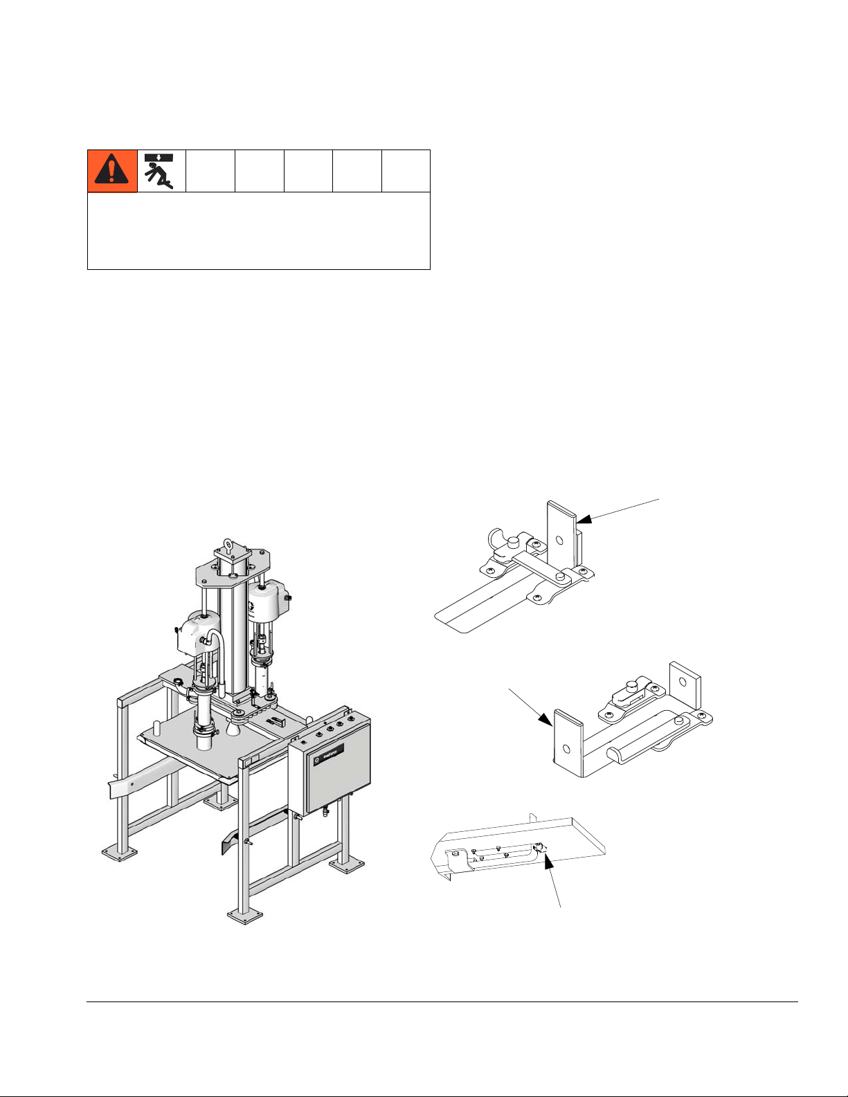
Manual Stop (all models)
Engage Position
Disengage
Position
Lock Position
Move latch until tab snaps into
roller grab mounted under frame.
TI16236a
TI17829a
TI17828a
TI15702a
The overall system weighs about 2400-3400 lb.
(1089-1542 kg). To avoid injury, always set manual
stop latch to Engage position when working under
the plate.
Engaging
1. Raise plate until it stops at the top.
Manual Stop (all models)
Lockout
A lockout has been provided to lock the plate in the
raised position.
1. Engage the manual stop. See Engaging.
2. Insert a padlock through the hole in the handle and
the mating piece on the frame.
NOTE: Follow any national and state lockout/tagout
codes and local regulations.
2. Set latch to Engage position. See F
IG. 8.
Disengaging
1. Make sure plate is raised all the way up (not resting
on stop).
2. Move latch to Disengage position. See F
IG. 8.
FIG. 8. Manual Stop (BESA7A shown)
311163ZAC 15
Page 16
Manual Control System
B
A
D
G
L
K
J
H
F
E
C
Tee is used on four
pump systems only
ti22760
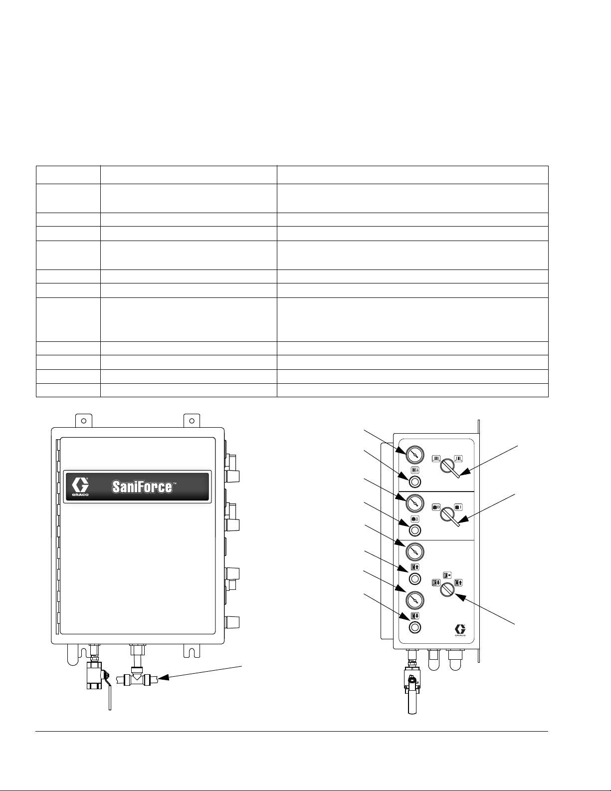
Manual Control System
Part No. 15E523 Manual Control
See FIG. 9.
Ref. Key Switch/Button Name Operation
A Seal Inflate On/Off Switch to ON to inflate ram plate seal.
Switch to OFF to deflate ram plate seal.
B Ram Plate Seal Pressure Gauge Displays Ram plate seal pressure.
C Ram Plate Seal Regulator Adjust to raise or lower ram plate seal pressure.
D Pump On/Off Switch to ON to run the pumps.
Switch to OFF to stop the pumps.
E Pump Pressure Gauge Displays current pump pressure.
F Pump Pressure Regulator Adjust to raise or lower pump inlet air pressure.
G Ram Directional Switch Switch to UP to raise the ram plate.
Switch to DOWN to apply ram pressure to the material.
Switch to NEUTRAL to hold the position of the ram plate.
H Ram Up Pressure Gauge Displays Ram Up operation pressure.
J Ram Up Regulator Adjust to raise or lower ram up pressure.
K Ram Down Pressure Gauge Displays Ram Down operation pressure.
L Ram Down Regulator Adjust to raise or lower ram down pressure.
FIG. 9: Part No. 15E523 Manual Control
16 311163ZAC
Page 17
Manual Control System
Pressure Relief Procedure
Trapped air can cause the pump to cycle
unexpectedly, which could result in serious injury
from injection, splashing or moving parts. Relieve
pressure when you stop pumping and before
cleaning, checking, or servicing equipment.
1. To turn off the pumps move pump switch to OFF.
2. Shut off the air to the pumps by closing the
bleed-type air shutoff valve on the pumps’ air supply
line, or disconnect the air line.
3. Open all system fluid drain valves that are downstream of the pumps.
Initial Startup
NOTE: Pump cavitation occurs when the pump cylinder
does not fully load with material on the up stroke and an
air pocket forms in the material after the pump changeover. If pump cavitation occurs, increase the ram down
air pressure.
10. Adjust the seal vacuum pump air regulator to 15 psi
(103 kPa, 1.0 bar).
11. Deflate the seal.
12. Press the RAM UP button. If the ram does not raise,
increase the ram up air regulator pressure.
13. Verify the seal is completely deflated after the ram
plate exits the bin. If it is not, deflate the seal.
14. When adjustments are complete, close the pneumatic control panel door.
15. Follow Unloading the Bin procedure, page 18.
16. The system is now ready for standard operation.
See page 17.
When raising or lowering the ram plate, keep hands
and body away from ram plate and bin lip.
This procedure takes you through the settings, adjustments, and other steps that must be completed before
the system is ready for daily operation.
1. Fill all the pumps packing nut/wet cups 1/3 full with a
compatible lubricant if applicable. Refer to your
pump manual for details. Do not use Graco Throat
Seal Lubricant with a sanitary application.
2. Turn on the air to the pneumatic control panel.
3. Turn SEAL INFLATE to OFF.
4. Open the air shutoff valves for the pneumatic controls and pumps.
5. Open the pneumatic control panel door. Check for
air leaks.
6. The equipment was tested with water. Flush the
system before loading material. See page 28.
Setting Air Pressures
Each system function has an associated air pressure.
Air pressure regulators are located on the pneumatic
control panel. Set initial air pressures as shown in the
table below. Make adjustments as needed during operation. See F
Ref.
Key
B* SEAL INFLATE 7 (48, 0.5)
H RAM UP 30 (207, 2.1)
K RAM DOWN 30 (207, 2.1)
E PUMP 50 (345, 3.4)
*A pressure relief regulator is required when a control
system other than a Graco control panel is used.
IG. 9.
Function Regulator Setting
psi (kPa, bar)
Max: 15 (103, 1.0)
7. Follow Loading the Bin procedure, page 18.
8. Set the ram down air regulator to 30 psi (207 kPa,
2.1 bar). Adjust as needed.
9. Adjust the pump regulator as needed.
311163ZAC 17
Page 18
Manual Control System
38*
37*
21
39
TI16235a
* Not used with BESCCC.
Standard Operation
Loading the Bin
When raising or lowering the ram plate, keep hands
and body away from ram plate and bin lip.
NOTE: When raising and lowering the ram plate, make
sure there are no objects obstructing the unit.
1. Open the air shutoff valves for the air controls and
pumps.
2. On the control panel, switch to the RAM UP position. If the ram does not elevate, increase the ram
up air regulator pressure on the pneumatic control
panel.
3. Move the bin in front of the frame.
4. Remove the lid from the fluid bin to expose the fluid
bag. If present, open the outer plastic bag and pull it
up over the sides of the bin, exposing the aseptic
inner bag.
12. Use the ram plate handles to center the ram plate
inside the bin. Be careful not to pinch the inflatable
seal when it enters the bin.
5. Make sure the bag is taut and secure it in place.
6. Secure the bag sides by using clamps (37) and
tubes (38). See F
7. Load the bin of material into the center of the frame.
Center the bin with the ram plate.
8. Initial Startup Only: The frame has spring-loaded
guides to stabilize the bin. Adjust the guides equally
with the screws on all four sides of the bin. Leave
enough space between guides and bin to allow for
removal of the bin.
9. Make sure the corner seals (21) are in place.
10. Use corners (39) to help guide the plate. See F
10.
11. Switch to the Ram Down position
IG. 10.
FIG. 10
Unloading the Bin
NOTE: When raising and lowering the ram plate, make
sure there are no objects obstructing the unit.
1. Follow the Pressure Relief Procedure, page 17.
2. Ensure seal is deflated and ram is raised.
IG.
3. Unload the bin from the frame.
System Shutdown
Follow the Pressure Relief Procedure, page 17.
Depending on the type of material, it may be best to
deflate the seal and raise the ram plate out of the material or keep the ram plate lowered in the bin. Some
materials dry and harden when exposed to air. Cover
materials when they are not being used.
18 311163ZAC
Page 19
Electronic Control System
Key:
A Pumps 1-4 Air Supply
B Control Box Air Supply
C Seal Air
DRam Down Air
ERam Up Air
F Pump 1 Air
G Pump 2 Air
H Pump 3 Air
J Pump 4 Air
K Exhaust Muffler
CDEFGHJ
ti19841a
K
B
A
Electronic Control System
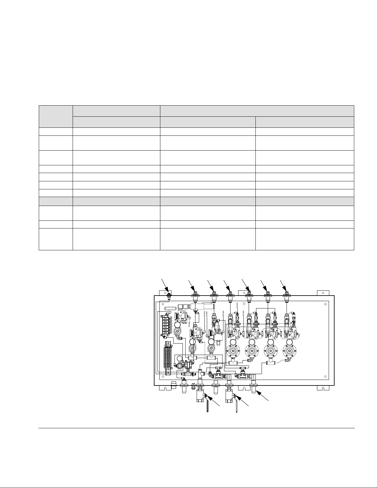
Connecting Pneumatic Control Panel Air Lines
Air supply to panel must be filtered, dry and capable of delivering a minimum of 100 scfm at 100 psi (0.7 MPa, 7 bar).
Refer to the table below and the Pneumatic Diagrams, pages 57 and 58, to make the top and bottom panel connections.
Origin Destination
Ref. Key
C Seal Air Supply Ram Plate Seal Inflates ram plate seal.
D Cylinder Upper Air Supply Upper Port On Air Cylinder Applies down force on ram plate when
E Cylinder Lower Air Supply Lower Port On Air Cylinder Applies up force on ram plate when
F Pump 1 Air Supply Pump 1 Supplies air to pump 1.*
G Pump 2 Air Supply Pump 2 Supplies air to pump 2.*
H Pump 3 Air Supply Pump 3 Supplies air to pump 3.*
J Pump 4 Air Supply Pump 4 Supplies air to pump 4.*
Top Panel Connections Component Connections Function
RAM PRESS is selected.
RAM UP is selected.
Bottom Panel Connections Pneumatic Source Connections
B Air Controls Air Inlet —
1/2 in. npt(f)
A Pumps Air Inlet — 1 in. npt(f) Pumps Air Supply Line Supplies input air pressure to pumps.
K Exhaust (no air line connection is
needed)
* Pump air valves open when PUMP SLOW or PUMP FAST (SV1 or SV2) are activated.
Air Controls Air Supply Line Supplies air to open and close air
valves.
Air Controls Exhaust Line Connects to a muffler that expels pres-
surized air from system when ram plate
is raised or seal deflated.
FIG. 11: Air Control Panel (570193, 4 pump shown)
311163ZAC 19
Page 20
Electronic Control System
Installing Electronic Control Panel
• Locate the electronic control panel so the
operator has an unobstructed view of the
SaniForce BES to avoid starting equipment when
other personnel could be injured.
• All electrical wiring must be done by a qualified
electrician and comply with all local codes and
regulations.
Mount the electronic control panel in a level, vertical
position on a sturdy surface. Make sure there is enough
room to open the enclosure door.
Connect 110 VAC (20 amp) power to the POWER IN
cable connector. The 110 VAC line must be rigidly piped.
Connect 24 VDC cable between the electronic and
pneumatic control panels.
If a flow meter is used, its cable must also be connected
to the electronic control panel. Contact the flow meter
supplier for installation information.
Discrete Devices 110 VAC
Manual Push Buttons
Emergency Stop
Power
Manual Selector Switches
Seal Inflate
Pump Slow
Pump Fast
Digital Inputs 24 VDC
Ram Jog
Ram Up
Start
Stop
High Speed Counter. . . . . Flow meter sensor
Ram Low . . . . . . . . . . . . . Proximity switch 1
Seal Inflate . . . . . . . . . . . . PSI switch 1
Standard Functions
Start . . . . . . . . . . . . . . . . . Initiates pumping cycle*
Stop . . . . . . . . . . . . . . . . . Activates seal deflate**
Seal Inflate . . . . . . . . . . . . Activates seal deflate*
Seal Deflate . . . . . . . . . . . Activates seal deflate*
Ram Up . . . . . . . . . . . . . . Initiates ram up*
Ram Jog. . . . . . . . . . . . . . Activates ram jog*
Ram Press . . . . . . . . . . . . Initiates ram press*
Pump Slow . . . . . . . . . . . . Activates pumps in slow
mode*
Pump Fast . . . . . . . . . . . . Initiates pumps in fast
mode*
Digital Outputs 24 VDC
Pumps 1 and 2 On Slow. . Solenoid 1
Pumps 1 and 2 Fast . . . . . Solenoid 2
Ram Press . . . . . . . . . . . . Solenoid 3
Ram Up Solenoid 4
Ram Jog Solenoid 5
Seal Off (vacuum
pump on) . . . . . . . . . . . . . Solenoid 6
Seal On . . . . . . . . . . . . . . Solenoid 7
Optional Remote Output . Energized during a pump
cycle
* Normally open
** Normally closed
20 311163ZAC
Page 21

Part No. 15H145 and 15J902 Electronic Control Panel
"%3#/.42/,"%3#/.42/,
0RESET0RESET
0RESET0RESET
0RESET0RESET
023
023
456456
'()
'()
*+,
*+,
3HIFT3HIFT
%SC%SC
%NTER%NTER
3YSTEM3YSTEM
789789
-./-./
!#45!,6!,5%!#45!,6!,5%
4!2'%46!,5%4!2'%46!,5%
02%3%4'!,,/.302%3%4'!,,/.3
0RESET0RESET
0RESET0RESET
0RESET0RESET
1:1: !"#!"# $%&$%&
3TROKE3TROKE
3ET5P3ET5P
+
&ACTOR&ACTOR
5-5-
4OTALIZER4OTALIZER
-ETER-ETER
3CREEN3CREEN
0UMPS0UMPS
%NABLE%NABLE
3,/73,/7
3%!,3%!,
/&&/&& /./.
2!-502!-50
34!2434!24
34/034/0
!54/!54/
05-005-0
-!.-!.&!34&!34 "!4#("!4#(
2!-02%332!-02%33
2!-*/'2!-*/'
%34/0%34/0
0/7%20/7%2
'2!#/'2!#/
R
A
B
C
D
EFG H
J
K
Ref. Key Switch/Button Name Operation
A SEAL INFLATE Press to inflate ram plate seal
B RAM JOG Press button to slowly lower ram (by exhausting ram up
air pressure). Generally used when guiding ram plate into
bin or making system adjustments.
C RAM UP Press button to raise ram.
D RAM PRESS Press button to lower ram onto material using air pres-
sure.
E STOP Press button to stop operation of the pumps, ram and
automatic cycle.*
F PUMP SPEED SWITCH Turn switch to select the pump speed.
G MODE SELECTOR SWITCH Turn switch to select the ram operation mode.
H EMERGENCY STOP Press button to immediately shut off air to the system and
stop operation.*
J START Press button to begin operation.
K POWER Press button to enable power to the electronic control
panel.
*The air cylinder will stabilize in its current position.
Electronic Control System
FIG. 12: Part No. 15H145 and 15J902 Electronic Control
311163ZAC 21
Page 22

Electronic Control System
4
641
15
Proximity Switch
The low limit proximity switch (641) is located near the
air cylinder (mounting plate (15) and can be adjusted to
operate at different levels in the bin. See F
The pumps operate in fast mode until the ram plate
reaches the low limit. The proximity switch changes the
pumps to the slow mode operation for a user selected
amount of time, after which the pumps stop, the seal
deflates, and the ram raises.
IG. 13.
The system timer controls how long the pumps run at
slow speed at the end of bin evacuation. After the time
elapses, the controller stops the pumps, deflates the
seal, and raises the ram up.
NOTE: See Setting the Bin Empty Timer and Setting
the Vacuum Pump Timer, page 24, for additional infor-
mation on adjusting the proximity switch and system
timer.
FIG. 13: Proximity Switch
22 311163ZAC
Page 23

Electronic Control System
A
BCDEFGH
ti19841a
Setting Air Pressures
Each system function has an associated air pressure.
Air pressure regulators are located in the pneumatic
control bin. Set initial air pressures as shown in the table
below. Make adjustments as needed during operation.
See F
IG. 14.
Ref. Function Regulator Setting
psi (kPa, bar)
A SEAL INFLATE 15 (103, 1.0) (Max.)
B RAM UP 30 (207, 2.1)
C RAM DOWN 30 (207, 2.1)
D PUMP 1 50 (345, 3.4)
E PUMP 2 50 (345, 3.4)
F *PUMP 3 50 (345, 3.4)
G *PUMP 4 50 (345, 3.4)
H SEAL VACUUM 20 (138, 1.4)
* Four pump systems only.
FIG. 14: Part No 570193, 4 pump shown
311163ZAC 23
Page 24

Electronic Control System
Pressure Relief Procedure
Trapped air can cause the pump to cycle
unexpectedly, which could result in serious injury
from injection, splashing or moving parts. Relieve
pressure when you stop pumping and before
cleaning, checking, or servicing equipment.
1. Press the STOP button to turn off the pumps.
2. Shut off the air to the pumps by closing the
bleed-type air shutoff valve on the pumps’ air supply
line, or disconnect the air line.
3. Open all system fluid drain valves that are downstream of the pumps.
Initial Startup
This procedure takes you through the settings, adjustments and other steps that must be completed before
the system is ready for daily operation.
NOTE: Press STOP button at any time to stop the system. See F
IG. 12.
Setting the Pump Slow Timer
The pump slow timer controls the amount of time that
the pumps will operate at the slow speed for priming the
pumps. This timer will be active when the plate is in the
bin, the control is set to AUTO, the seal is inflated and
the ram is pressurized down.
1. Press the Timer key to access the timer screens.
Continue to toggle the key until the PUMP SLOW
TIMER screen appears.
2. Press the Enter key to enable numerical entry.
3. Enter the desired set point - Minimum Value: 000,
Maximum Value: 999. Example (300 = 30 sec).
4. Press the Enter key a second time to accept the
value.
Setting the Bin Empty Timer
The bin empty timer controls the amount of time the
pumps operate at the slow speed for emptying the bin.
This timer will be activated when the ram is in AUTO
mode and the proximity switch has been tripped.
1. Press the Timer key to access the timer screens.
Continue to toggle the key until the BIN EMPTY
TIMER screen appears.
1. If applicable, fill all the pumps packing nut/wet cups
1/3 full with a compatible lubricant. Refer to your
pump manual for details. Do not use Graco Throat
Seal Lubricant with a sanitary application.
2. Press POWER button to turn on power to electronic
control panel.
3. Turn SEAL to OFF.
4. Open the air shutoff valves for the pneumatic controls and pumps.
5. Open the pneumatic control panel door. Check for
air leaks.
6. The equipment was tested with fluid. Flush the system before loading material. See page 28.
7. Follow Loading the Bin procedure, page 26.
2. Press the Enter key to enable numerical entry.
3. Enter the desired set point - Minimum Value: 000,
Maximum Value: 999. Example (300 = 30 sec).
4. Press the Enter key a second time to accept the
value.
Setting the Vacuum Pump Timer
The vacuum pump timer controls the amount of time the
vacuum pump operates to assist the deflation of the
seal. This timer will be activated when the ram is in
AUTO mode and the proximity switch has been tripped.
1. Press the Timer key to access the timer screens.
Continue to toggle the key until the VACUUM PUMP
TIMER screen appears.
2. Press the Enter key to enable numerical entry.
3. Enter the desired set point - Minimum Value: 000,
Maximum Value: 999. Example (300 = 30 sec).
4. Press the Enter key a second time to accept the
value.
24 311163ZAC
Page 25

Batch Mode Setup
The electrical control cabinet is designed to operate
optional batching functions. The batch mode will allow
the user to control the operation of the ram unit flow
meter output or pump stroke monitors. Additional equipment is required to operate in either of the batch modes.
The batch mode is factory set to “BATCHING DISABLED”. Refer to Electrical Control Box manual.
Electronic Control System
311163ZAC 25
Page 26

Electronic Control System
TI16235a
38
37
21
39
Standard Operation
NOTE: When raising and lowering the ram plate, make
sure there are no objects obstructing the unit.
Loading the Bin
1. Open the air shutoff valves for the air controls and
pumps.
2. On the electronic control panel, press the RAM UP
button. If the ram does not elevate, increase the ram
up air regulator pressure in the pneumatic control
panel.
3. Move the bin in front of the frame.
4. Remove the lid from the fluid bin to expose the fluid
bag. If present, open the outer plastic bag and pull it
up over the sides of the bin, exposing the aseptic
inner bag.
5. Secure the bag sides by using clamps (37) and
tubes (38). See F
IG. 15.
7. Initial Startup Only: The frame has spring-loaded
guides to stabilize the bin. Adjust the guides equally
with the screws on all four sides of the bin. Leave
enough space between guides and bin to allow for
removal of the bin.
8. Make sure the corner seals (21) are in place.
9. Use corners (39) to help guide the plate. See F
IG.
15.
10. Press the RAM JOG button.
NOTE: It can take 5-15 seconds for the ram plate to
start lowering.
When raising or lowering the ram plate, keep hands
and body away from ram plate and bin lip.
11. Use the ram plate handles to center the ram plate
inside the bin. Be careful not to pinch the inflatable
seal when it enters the bin.
FIG. 15
6. Load the bin of material into the center of the frame.
NOTE: The ram plate stops when it contacts the
material.
26 311163ZAC
Page 27

Automatic Evacuation of the Bin
TA RGET 1000 LBS RUN
ACTUAL 0000 LBS EXIT
1. On the Operator Interface, select TARGET/ACTUAL
RUN screen.
Press arrow ➜ to select RUN and press ENT.
2. Ram plate seal inflates.
3. Ram down air pressure is applied and pumps start
in slow mode, then switches to fast mode.
4. When the low limit setting is reached, the pumps
switch to slow mode for 2 minutes and then stop.
5. The ram plate seal deflates and the ram is raises.
Electronic Control System
Unloading the Bin
1. Follow the Pressure Relief Procedure, page 24.
2. Ensure seal is deflated and ram is raised.
3. Unload the bin from the frame.
System Shutdown
Follow the Pressure Relief Procedure, page 24.
Depending on the type of material, it may be best to
deflate the seal and raise the ram plate out of the material or keep the ram plate lowered in the bin. Some
materials dry and harden when exposed to air. Cover
materials when they are not being used.
311163ZAC 27
Page 28

Maintenance
Maintenance
Air Motor Icing
Air motor icing occurs when moisture in the compressed
air collects in the air motor and freezes, causing the
motor to stall. If icing occurs with any of the pumps, shut
off the air supply to all pumps and allow the ice to thaw.
NOTICE
Operating the system without all the pumps functioning can damage the system
To minimize icing:
• Reduce the moisture in your compressed air by
using an air dryer or filter, which traps water.
• Main air line should slope slightly downward so
water collects and can be drained at the end of the
line.
• Plumb a drop line from the top of each main air line.
Install an automatic drain or drain valve at the bottom of each drop.
To flush the system:
1. Load a bin containing water, compatible solvent, or
cleaning solution that can dissolve the material and
clean the system. Follow the procedure for Loading
the Bin, page 18 or page 27.
NOTE: Use solvent that is compatible with the equip-
ment wetted parts and the material you will dispense.
See Technical Data in your pump manual for wetted
parts and consult your material supplier.
2. Operate the pumps and circulate the cleaning fluid
through the system for about 1-2 minutes or until the
equipment is clean.
3. Remove the bin of cleaning fluid from the frame. Follow the procedure for Unloading the Bin, page 18
or page 27.
4. Operate the pumps at low pressure to remove
excess solvent.
5. Follow the Pressure Relief Procedure, page 17 or
page 24.
• Ensure air motor exhaust tube is outside of a refrigerated area.
Preventive Maintenance
Your system operating conditions determine how often
maintenance is required. Record when and what kind of
maintenance is needed to create a maintenance schedule.
Flushing the System
• The equipment was tested with water. Flush the
system before loading material.
• Flush regularly to avoid having material dry and
build up and possibly contaminate new material or
cause blockages.
Cleaning Pumps
1. Follow the Pressure Relief Procedure, page 17 or
page 24.
2. Remove pumps from plate and frame.
3. See the pump manual for maintenance and service
procedures.
• Flush at the lowest pressure possible. Check connectors for leaks and tighten them if necessary.
28 311163ZAC
Page 29

Cleaning Ram Plate and Seal
1. Follow the Pressure Relief Procedure, page 17 or
page 24. Keep the air supply to the ram open.
2. Raise the ram plate.
To avoid injury, always set manual stop latch to
Engage position when working under the plate.
3. Engage the manual stop.
4. Remove the inflatable seal and corner seals from
the ram plate.
5. Clean the seals and ram plate with a compatible
cleaning fluid.
6. Apply a generous amount of lubricant to the ram
plate channel and seals.
Maintenance
7. Install the inflatable seal and corner seals on the
ram plate. Position the inflatable seal so that the
seal bottom is angled into the ram plate channel.
311163ZAC 29
Page 30

Troubleshooting
Troubleshooting
Problem Cause Solution
Ram plate will not raise or
lower.
Pump(s) will not operate. Air pressure to the pump(s)
Pumps will not prime or are
cavitating.
Premature seal wear. SEAL and RAM DOWN air
Material leaking past seal. RAM DOWN air pressure is
Too much material left in
bottom of bin.
Air pressure to the ram is too
low.
Ram plate is stuck in bin. 1. Deflate seal.
is too low.
Ram plate is not in contact
with material.
Material bag was sucked into
pump.
pressures are too high.
too high.
Container bag is not pulled
taut or clamped for smooth
bin walls.
Corner seals are not in
place.
Container bag is bunched up
at bottom of bin
Increase RAM UP air pressure.
Turn SEAL INFLATE to OFF.
2. Switch to RAM UP position. When it is raised,
check for obstructions in bin or quality of seal.
Increase PUMP air pressure to a minimum of 30 psi
(207 kPa, 2.1 bar). Refer to pump manual.
• Check SEAL and RAM DOWN pressures and
adjust until you have a quality seal.
• Refer to troubleshooting in pump manual.
Shut off air to pumps, deflate seal, and raise ram to
clear pump intake.
Adjust SEAL and RAM DOWN air pressures until you
have proper seal and pump operation. Do not
over-pressurize the seal.
Reduce RAM DOWN pressure while ensuring pumps
are operating properly.
Pull bag tight and secure in place.
Install corner seals.
Reduce seal pressure while ensuring there is still a
good seal.
30 311163ZAC
Page 31

Service
Service
NOTE: See FIG. 16. All models do not use the same
parts. Refer to parts drawing for your model.
Before Servicing
To avoid injury, always set manual stop latch to
Engage position when working under the plate.
1. Remove the bin from the frame.
2. Follow the Pressure Relief Procedure, page 17 or
page 24.
3. Lower the ram plate and deflate the seal.
4. Shut off the air supply to the system.
Replacing Cylinder Bearing (All Models)
NOTICE
To avoid damaging equipment, replace each bearing
individually. Do not remove all four bearings at the
same time.
See FIG. 16.
1. Follow the Before Servicing procedure, page 31.
2. Remove screws (409) and washers (410), then take
cylinder guide bearings (408) off the air motor
mounting plate (402).
3. Install cylinder guide bearings (408) on top of the air
motor mounting plate (402), using screws (409) and
washers (410).
NOTE: The open arch in the cylinder guide bearings
(408) fits around tie rods on the air cylinder (4).
4. Repeat steps 2-3 as needed to replace additional
cylinder bearings.
5. Raise and lower the ram plate to check the bearings.
311163ZAC 31
Page 32

Service
TI16216a
TI16218a
21
502
501
29
4
408,
409,
410
402
Replacing Ram Plate Seal or Corner Seals (All Models)
See FIG. 16.
1. Follow the Before Servicing procedure, page 31.
2. If you are only replacing the corner seals (21)
and not the ram plate seal (501, remove the rivet
(22) and replace each corner seal individually. Do
not remove all 4 corner seals at the same time or
the ram plate seal may move out of place. Be careful not to puncture the ram plate seal. Skip to step 8.
If you are replacing the ram plate seal (501),
remove the rivets (22), then remove all 4 corner
seals (21). Check the corner seals for damage and
replace if necessary.
3. Disconnect the tube fitting (29) from the seal air
supply tube (14).
4. Remove the ram plate seal (501), using a blunt-end
tool to avoid damaging the seal. Carefully disengage the air stem from the hole in the ram plate
(502).
5. Insert the air stem of the new seal (501) into the ram
plate (502) hole. To avoid puncturing the new seal,
carefully slide the seal in place around the ram
plate.
6. Install the four corner seals (21) with rivets (22).
7. Connect the air supply tube (14) to the tube fitting
(29).
8. Check operation by inflating and deflating the seal.
Check for air leaks. After loading a bin of material
into the frame, check whether material leaks around
the ram plate and seals.
FIG. 16: Repair (BESA7A Shown)
32 311163ZAC
Page 33

Service
4
641
15
B
TI16238a
Replacing Proximity Switch (Electronic Control Models Only)
See FIG. 17.
1. Follow the Before Servicing procedure, page 31.
2. Mark the proximity switch (641) position on its
bracket (B) to ensure the new switch is installed the
same. Refer to F
NOTE: Graco recommends 1/4 in. (6.35 mm) space
between switch and plate (15).
3. Disconnect the cable from the switch (641).
4. Remove the two screws, lock washers, and the
switch.
5. Secure the new switch to the bracket (B) with the
screws and lock washers.
6. Reconnect the cable.
7. Restart the system and verify the switch operates
correctly.
IG. 17.
Electronic Control Panel Service (Electronic Control Models Only)
Follow the Before Servicing procedure, page 31. Consult a qualified electrician to service the control panel.
FIG. 17: Proximity Switch
311163ZAC 33
Page 34

SaniForce BES Pump Matrices
SaniForce BES Pump Matrices
To determine the Model No. of your Bin Evacuation System from the following matrices, select the six digits which
describe your system, working from left to right. The first three digits are always B E S, designating Bin Evacuation
System. The remaining three digits designate pump, plate, and controls used. To order replacement parts, refer to
the parts lists on pages 38-55.
3150 AODD Pumps
Bin
Evacuation
System
B E S 3
SaniForce 3150 Ball Check, 2 pumps
SaniForce 3150 Flapper Check, 2 pumps
4
SaniForce 3150, 3A, Ball Check, 2 pumps
8
Pump Module
(see pages 38-45)
Plate
(see page 46)
Arena
A
Pallecon
B
GoodPak
F
MB5
Plywood
P
Controls/Frame
(see pages 46-56)
Electronic Controls, Allen-Bradley
1
Micrologix, 2 Pumps
Manual Controls, 2 Pumps
3
Available Configurations*
Model Pump Plate Controls/Frame
BES3P1 3150 Ball Check Plywood Electronic
BES3P3 3150 Ball Check Plywood Manual
BES4P3 3150 Flapper Check Plywood Manual
BES3A1 3150 Ball Check Arena Electronic
BES4A1 3150 Flapper Check Arena Electronic
BES8B3 3150 3A Ball Check Pallecon Manual
BES3F3 3150 3A Ball Check GoodPak MB5 Manual
* Contact your Graco distributor if you require a configuration that is not listed.
34 311163ZAC
Page 35

Piston Pumps
Bin
Evacuation
System
B E S A
Pump Module
(see pages 38-45)
5:1 SaniForce,
Double Ball, 2 pumps
(see page 46)
330 Arena Bin
1
Plate
SaniForce BES Pump Matrices
Controls/Frame
(see pages 46-56)
Electronic Controls, Allen-Bradley
A
Micrologix, 2 Pumps
5:1 SaniForce
B
Double Ball, 4 pumps
5:1 SaniForce
C
Priming Piston, 2 pumps
6:1 SaniForce
D
Priming Piston, 2 pumps
12:1 SaniForce
E
Priming Piston, 2 pumps
12:1 SaniForce
F
Priming Piston, 4 pumps
Chep
3
Ceva Pallecon,
4
2 pumps, 5:1
Ceva Pallecon,
5
2 pumps, 12:1
Arena Bin, 4 pumps
6
Plywood
7
TNT
9
Caliber 315 Buckhorn
A
Bin, 2 pumps
Goodpack MB5 Bin, 2
B
pumps
KC Bin
C
Available Configurations*
Model Pump Plate Controls/Frame
BESA4C 5:1, 2 pumps Ceva Pallecon Manual
BESAAC 5:1, 2 pumps Buckhorn Manual
BESA7A 5:1, 2 pumps Plywood Electronic, Micrologix
BESA7C 5:1, 2 pumps Plywood Manual
BESA7F 5:1, 2 pumps Plywood Electronic, Contrologix
BESB7B 5:1, 4 pumps Plywood Electronic, Micrologix
BESB7D 5:1, 4 pumps Plywood Manual
BESCCC 5:1, 2 pumps KC Bin Manual
BESDBC 6:1, 2 pumps Goodpack MB5 Manual
BESE1A 12:1, 2 pumps Arena Electronic, Micrologix
BESE1C 12:1, 2 pumps Arena Manual
BESE5C 12:1, 2 pumps Ceva Pallecon Manual
BESE7C 12:1, 2 pumps Plywood Manual
BESEAC 12:1, 2 pumps Buckhorn Manual
BESF6B 12:1, 4 pumps Arena Electronic, Micrologix
BESF6D 12:1, 4 pumps Arena Manual
BESF7B 12:1, 4 pumps Plywood Electronic, Micrologix
BESF7D 12:1, 4 pumps Plywood Manual
BESF9B 12:1, 4 pumps TNT Electronic, Micrologix
BESF9D 12:1, 4 pumps TNT Manual
Electronic Controls, Allen-Bradley
B
Micrologix, 4 Pumps
Manual Controls, 2 Pumps
C
Manual Controls, 4 Pumps
D
Electronic Controls, Allen-Bradley
F
Contrologix, 2 Pumps
* Contact your Graco distributor if you require a configuration that is not listed.
311163ZAC 35
Page 36

SaniForce BES Common Parts
SaniForce BES Common Parts
Ref.
No. Part No. Description Qty.
4 15K301 CYLINDER, air; sst 1
6 590570 TUBE, polyethylene; 1/2 in. (35 ft) OD*
7 514334 NUT; 3/4-10; Nylock 10
8 103473 STRAP, tie, wire (not shown) 12
9 103546 STRAP, tie, wire (not shown) 3
10 626520 GUIDE, box side 2
11 514819 SPRING, coil; sst 6
12 514332 WASHER; 3/4 in.; sst; 1.875 in. 12
13 551274 CASTER; sst; 125#; 1.75 in. 22
14 590385 TUBE, poly-flo (10 ft) *
16 625595 BEARING, thrust; PTFE 4
17 625596 WASHER, thrust; sst 4
18 514331 SCREW, cap, hex head 4
19 551363 WASHER, lock; 5/8 in.; sst 4
20 513386 SCREW, cap, hex head 4
21 15F205 SEAL, corner 4
22 551691 RIVET; 3/8 in. x 2-1/2 in.; sst 4
26 512684 FITTING, elbow, tube 2
28 107542 WASHER, lock, spring 4
29 112944 SCREW, cap 7
32 070303 LUBRICANT GREASE 1
Ref.
No. Part No. Description Qty.
33 C78216 CLAMP, ty-rap 2
36 111265 LUBRICANT, tube (not shown) 2
37 949412 CLAMP, bag (not shown); not used
with BESCCC
38 625988 TUBE, wand (not shown); not used
with BESCCC
39 626046 BIN, corner (not shown) 4
40 249064 COUPLING 1
43 16D911 SUPPORT, stop 1
44 15G112 HANDLE, stop 1
45 15G113 LATCH, stop 1
46 15D008 BOLT; 3/8-16; sst 2
47 15F979 SCREW, pan hd, phillips 4
48 15F988 NUT, lock, hex 4
51▲ C14043 LABEL, warning 1
53 104034 WASHER 4
60 16D899 SUPPORT, stop handle 1
61 16D895 CATCH, grab 1
62 16D913 SCREW, panhead 2
63 16D914 SCREW, fillister head 2
64 16D912 SPACER, stop 2
65 113003 SCREW, sockethead 4
▲ Replacement Danger and Warning labels, tags, and
cards are available at no cost.
4
4
36 311163ZAC
Page 37

SaniForce BES Common Parts (BESA7A shown)
20
"%3#/.42/,"%3#/.42/,
0RESET0RESET
0RESET0RESET
0RESET0RESET
023
023
456456
'()
'()
*+,
*+,
3HIFT3HIFT
%SC%SC
%NTER%NTER
3YSTEM3YSTEM
789789
-./-./
!#45!,6!,5%!#45!,6!,5%
4!2'%46!,5%4!2'%46!,5%
02%3%4'!,,/.302%3%4'!,,/.3
0RESET0RESET
0RESET0RESET
0RESET0RESET
1:1: !"#!"# $%&$%&
3TROKE3TROKE
3ET5P3ET5P
+
&ACTOR&ACTOR
5-5-
4OTALIZER4OTALIZER
-ETER-ETER
3CREEN3CREEN
0UMPS0UMPS
%NABLE%NABLE
3,/73,/7
3%!,3%!,
/&&/&& /./.
2!-502!-50
34!2434!24
34/034/0
!54/!54/
05-005-0
-!.-!.&!34&!34 "!4#("!4#(
2!-02%332!-02%33
2!-*/'2!-*/'
%34/0%34/0
0/7%20/7%2
'2!#/'2!#/
R
19
17
18
16
15
7
13
7
12
10
11
26
6
33
4
53
28
47
40
21
14
29
22
See pages 38-45
See page 46
See page 46
See page 35
23
See page 47
45
44
Detail of Manual Stop
47
46 48
▲51
TI16216a
TI16237a
TI16217a
64
65 43
61
63
4660 62 61
SaniForce BES Common Parts
311163ZAC 37
Page 38

Pump Modules
401
408
409, 410
402
412, 413
403
412, 413
405, 411
404
415
416
TI16539a
TI16538a
TI16540a
425
424
423
423
406, 407
Pump Modules
Models 24G560 and 24G968, 5:1 SaniForce Double Ball Pump
Module (2 Pumps)
Ref.
No. Part No. Description Qty.
401 24G742 PUMP, 5:1 SaniForce;
402 16E388 PLATE, motor mount 1
403 513490 ELBOW; 2 in.; sst 2
404
405 551365 SCREW, hex hd; 3/4-10 x 2 in. 2
406 16D246 GASKET, 6 in. 2
407 16D245 CLAMP, 6 in. 2
408 625752 BEARING, cylinder guide 4
409 104119 SCREW, cap, hex head; 1/4-20 x
410 170772 WASHER, plain 8
411 551364 WASHER, lock; 3/4 in.; sst 2
38 311163ZAC
16G494
16G208
see manual 3A0734
ROD, motor mount
7/8 in. (22 mm); sst
Used on Model BESA4_
Used on Models BESA7_
Ref.
No. Part No. Description Qty.
412 500984 CLAMP, 2 in. tri-clamp 4
2
413 512332 GASKET, S-clamp; buna-N 4
414 ----- CLAMP, for air motor drain hose
415 16F384 FITTING, air inlet, 1/2 np x 1/2
2
416 16A942 FITTING, exhaust hose 2
423 101818 CLAMP, hose 4
424 512914 MUFFLER, polyethylene, 1 in.
425 ----- HOSE, exhaust, 6 ft. 2
426 ----- HOSE, air motor drain, 6 ft.
8
(not shown)
ptc
npt
(not shown)
2
2
2
2
Page 39

Model 24P829, 5:1 SaniForce Priming Piston Pump Module
401
408
409, 410 402
412, 413
403
412, 413
405, 411
415
416
Ti20068b
Ti20069b
Ti20070b
425
424
423
423
406, 407
(2 Pumps)
Pump Modules
Ref.
No. Part No. Description Qty.
401 24R233 PUMP, 5:1 SaniForce;
see manual 3A0734
402 16E388 PLATE, motor mount 1
403 513490 ELBOW; 2 in.; sst 2
405 551365 SCREW, hex hd; 3/4-10 x 2 in. 2
406 16D246 GASKET, 6 in. 2
407 16D245 CLAMP, 6 in. 2
408 625752 BEARING, cylinder guide 4
409 104119 SCREW, cap, hex head; 1/4-20 x
7/8 in. (22 mm); sst
410 170772 WASHER, plain 8
411 551364 WASHER, lock; 3/4 in.; sst 2
Ref.
No. Part No. Description Qty.
412 500984 CLAMP, 2 in. tri-clamp 4
2
413 512332 GASKET, S-clamp; buna-N 4
414 ----- CLAMP, for air motor drain hose
415 16F384 FITTING, air inlet, 1/2 np x 1/2 ptc 2
416 16A942 FITTING, exhaust hose 2
423 101818 CLAMP, hose 4
424 512914 MUFFLER, polyethylene, 1 in. npt 2
425 ----- HOSE, exhaust, 6 ft. 2
8
426 ----- HOSE, air motor drain, 6 ft.
(not shown)
(not shown)
2
2
311163ZAC 39
Page 40

Pump Modules
401
408
409, 410
402
412, 413
403
412, 413
405, 411
404
417
416
TI16541a
TI16542a
TI16543a
423
425
406, 407
401
424
423
Model 24G561, 5:1 SaniForce Double Ball Pump Module
(4 Pumps)
Ref. Part No. Description Qty.
401 24G742 PUMP, 5:1 SaniForce;
402 16G201 PLATE, motor mount 1
403 513490 ELBOW; 2 in.; sst 4
404 16G208 ROD, motor mount 4
405 551365 SCREW, hex hd; 3/4-10 x 2 in. 4
406 16D246 GASKET, 6 in. 4
407 16D245 CLAMP, 6 in. 4
408 625752 BEARING, cylinder guide 4
409 104119 SCREW, cap, hex head; 1/4-20 x
410 170772 WASHER, plain 8
411 551364 WASHER, lock; 3/4 in.; sst 4
see manual 3A0734
7/8 in. (22 mm); sst
4
8
Ref. Part No. Description Qty.
412 500984 CLAMP, 2 in. tri-clamp 8
413 512332 GASKET, S-clamp; buna-N 8
414 ----- CLAMP, for air motor drain hose
(not shown)
415 16F384 FITTING, air inlet, 1/2 np x 1/2 ptc 4
416 16A942 FITTING, exhaust hose 4
423 101818 CLAMP, hose 8
424 512914 MUFFLER, polyethylene, 1 in. npt 4
425 ----- HOSE, exhaust, 6 ft. 4
426 ----- HOSE, air motor drain, 6 ft.
(not shown)
4
4
40 311163ZAC
Page 41

Model 24P815, 6:1 SaniForce Priming Piston Pump Module
401
408
409, 410
402
412, 413
403
412, 413
405, 411
404
415
416
TI20996a
TI20997a
Ti20998a
425
424
423
423
406, 407
(2 Pumps)
Pump Modules
Ref.
No. Part No. Description Qty.
401 24D659 PUMP, 6:1 SaniForce;
see manual 3A0733
402 16E388 PLATE, motor mount 1
403 51A796 ELBOW; 2 in.; sst 2
404 16T894 ROD, motor mount 2
405 551365 SCREW, hex hd; 3/4-10 x 2 in. 2
406 16D246 GASKET, 6 in. 2
407 16D245 CLAMP, 6 in. 2
408 625752 BEARING, cylinder guide 4
409 104119 SCREW, cap, hex head; 1/4-20 x
410 170772 WASHER, plain 8
411 551364 WASHER, lock; 3/4 in.; sst 2
7/8 in. (22 mm); sst
Ref.
No. Part No. Description Qty.
412 118598 CLAMP, 1.5 in. tri-clamp 4
2
413 16D169 GASKET, buna-N 4
414 ----- CLAMP, for air motor drain hose
(not shown)
415 16F384 FITTING, air inlet, 1/2 np x 1/2
ptc
416 16A942 FITTING, exhaust hose 2
423 101818 CLAMP, hose 4
424 512914 MUFFLER, polyethylene, 1 in. npt 2
425 ----- HOSE, exhaust, 6 ft. 2
8
426 ----- HOSE, air motor drain, 6 ft
(not shown)
2
2
2
311163ZAC 41
Page 42

Pump Modules
401
406, 407
408
409, 410 402
405, 411
404
403 403
412
Model 249488, 24E441, and 24C125 3150 SaniForce Ball Check
Pump Module (2 Pumps)
Ref. Part No. Description
401 248273 PUMP, sanitary SaniForce, ball
24E440 PUMP, sanitary SaniForce, ball
24C124 PUMP, sanitary SaniForce, ball
402 15E473 PLATE, guide; for module 249488
16E157 PLATE, guide; for module 24E441 1
403 15E477 SUPPORT, pump 2
404 15K216 ROD, tie 2
405 551364 ELBOW; 1/2-14 npt(m) x 1/2 in.
406 510490 TRI-CLAMP, 4 in. 4
407 15H460 GASKET, tri-clamp 4
408 625752 BEARING, cylinder guide 4
42 311163ZAC
check; for module 249488, see
manual 310622
check; for module 24E441, see
manual 310622
check, for module 24C125, see
manual 310662
and 24C125
(13 mm) OD; nylon
Qty.
Ref. Part No. Description
409 104119 SCREW, cap, hex head; 1/4-20 x
2
410 170772 WASHER, plain 8
411 514334 WASHER, lock; 3/4 in.; sst 2
2
412 512684 NUT, 3/4-10 Nylock 2
414 500263 ELBOW; 3/4-14 npt x 1.5 in.
415 171439 NIPPLE; 1-11.5 npt x 3/4-14 npt,
1
416 551298 COUPLING, hose, 1-1/4 in.
417 101818 CLAMP, hose 4
418 512914 MUFFLER, polyethylene, 1 in. npt 2
419 551297 HOSE, 1-1/4 in. (32 mm); 20 in. 2
2
7/8 in. (22 mm); sst
(38 mm), 304 stainless steel
303 stainless steel
(32 mm)
Qty.
8
2
2
4
Page 43

Model 249489 3150 SaniForce Flapper Check Pump Module
401
406, 407
408
409, 410 402
405, 411
404
403 403
412
(2 Pumps)
Pump Modules
Ref. Part No. Description Qty.
401 248274 PUMP, sanitary SaniForce, flapper
402 15E473 PLATE, guide 1
403 15E477 SUPPORT, pump 2
404 15K216 ROD, tie 2
405 514334 NUT, 3/4-10 Nylock 2
406 510490 TRI-CLAMP, 4 in. 4
407 15H460 GASKET, tri-clamp 4
408 625752 BEARING, cylinder guide 4
409 104119 SCREW, cap, hex head; 1/4-20 x
410 170772 WASHER, plain 8
check; see manual 310622
7/8 in. (22 mm); sst
Ref. Part No. Description Qty.
411 551364 WASHER, lock; 3/4 in.; sst 2
2
412 512684 ELBOW; 1/2-14 npt(m) x 1/2 in.
414 500263 ELBOW; 3/4-14 npt x 1.5 in.
415 171439 NIPPLE; 1-11.5 npt x 3/4-14 npt,
416 551298 COUPLING, hose, 1-1/4 in.
417 101818 CLAMP, hose 4
418 512914 MUFFLER, polyethylene, 1 in. npt 2
8
419 551297 HOSE, 1-1/4 in. (32 mm); 20 in. 2
(13 mm) OD; nylon
(38 mm), 304 stainless steel
303 stainless steel
(32 mm)
2
2
2
4
311163ZAC 43
Page 44

Pump Modules
401
408 409, 410 402
412, 413
403
412, 413
405, 411
404
417
416
TI16240a
TI16239a
TI16241a
425
424
423
423
406, 407
Model 24G564 and 24G969 12:1 SaniForce Priming Piston
Pump Module (2 Pumps)
Ref. Part No. Description Qty.
401 24F625 PUMP, 12:1 SaniForce; see
manual 3A0735
402 16E388 PLATE, motor mount 1
403 513490 ELBOW; 2 in.; sst 2
404 ROD, motor mount 2
16G208 Model 246564
16G494 Model 24G969
405 551365 SCREW, hex, 3/4-10; sst 2
406 16D246 GASKET, 6 in. Sanitary 2
407 16D245 CLAMP, 6 in. Sanitary 2
408 625752 BEARING, cylinder guide 4
409 104119 SCREW, cap, hex head; 1/4-20 x
7/8 in. (22 mm); sst
2
8
Ref. Part No. Description Qty.
410 170772 WASHER, plain 8
411 551364 WASHER, lock; 3/4 in.; sst 2
412 500984 CLAMP, 2 in. tri-clamp 4
413 512332 GASKET, S-clamp; buna-N 4
414 ----- CLAMP, for air motor drain hose
(not shown)
415 16F384 FITTING, air inlet, 1/2 np x 1/2 ptc 2
416 16A942 FITTING, exhaust hose 2
423 101818 CLAMP, hose 4
424 512914 MUFFLER, polyethylene, 1 in. npt 2
425 ----- HOSE, exhaust, 6 ft. 2
426 ----- HOSE, air motor drain, 6 ft. (not
shown)
2
2
44 311163ZAC
Page 45

Part No. 24G566 and 24G970 12:1 SaniForce Priming Piston
401
408 409, 410 402
412, 413
403
412, 413
405, 411
404
417
416
TI16242a
TI16243a
TI16244a
423
424
425
406, 407
Pump Module (4 Pumps)
Pump Modules
Ref. Part No. Description Qty.
401 24F625 PUMP, 12:1 SaniForce; see
402 16G201 PLATE, motor mount 1
403 513490 ELBOW; 2 in.; sst 4
404 ROD, motor mount 4
16G208 Model 24G566
16G494 Model 24G970
405 551365 SCREW, hex, 3/4-10; sst 4
406 16D246 GASKET, 6 in. Sanitary 4
407 16D245 CLAMP, 6 in. Sanitary 4
408 625752 BEARING, cylinder guide 4
409 104119 SCREW, cap, hex head; 1/4-20 x
manual 3A0735
7/8 in. (22 mm); sst
Ref. Part No. Description Qty.
410 170772 WASHER, plain 8
4
411 551364 WASHER, lock; 3/4 in.; sst 4
412 500984 CLAMP, 2 in. tri-clamp 8
413 512332 GASKET, S-clamp; buna-N 8
414 ----- CLAMP, for air motor drain hose
415 16F384 FITTING, air inlet, 1/2 np x 1/2 ptc 4
416 16A942 FITTING, exhaust hose 4
423 101818 CLAMP, hose 4
424 512914 MUFFLER, polyethylene, 1 in. npt 4
425 ----- HOSE, exhaust, 6 ft. 4
426 ----- HOSE, air motor drain, 6 ft. (not
8
(not shown)
shown)
4
4
311163ZAC 45
Page 46

Inflatable Seal, Plate, Frames, and Controls
Inflatable Seal, Plate, Frames, and Controls
Electronic
Inflatable
Seal*
Model
BESA7A 514984 16E391 15E339 949949 15H145 ----- 249493
BESA7F 514984 16E391 15E339 949949 15J902 ----- 249493
BESB7B 514984 16E397 570192 570193 15H145 ----- 249493
BES3A1 551413 15U256 15E339 949949 15H145 ----- 249493
BES3P1 514984 15E348 15E339 949949 15H145 ----- 249493
BES4A1 551413 15U256 15E339 949949 15H145 ----- 249493
BESE1A 551413 16E393 15E339 949949 15H145 ----- 249493
BESF6B 551413 16E395 570192 570193 15H145 ----- 249493
BESF9B 116464 16E396 570192 570193 15H145 ----- 249493
BESA4C 16A383 16E392 15E339 15E523 ----- ----- -----
BESA7C 514984 16E391 15E339 15E523 ----- ----- -----
BESAAC 514984 16M012 15E339 15E523 ----- ----- -----
BESB7D 514984 16E397 570192 15M343 ----- ----- -----
BESCCC 16X394 16U774 16U789 15E523 ----- ----- -----
BES3F3 16D785 16D808 16D826 15E523 ----- ----- -----
BES3P3 514984 15E348 15E339 15E523 ----- ----- -----
BES4P3 514984 15E348 15E339 15E523 ----- ----- -----
BES8B3 16A383 16A381 15E339 15E523 ----- ----- -----
BESDBC 16D785 16T895 16D826 15E523 ----- ----- -----
BESE1C 551413 16E393 15E339 15E523 ----- ----- -----
BESE5C 16A383 16E392 15E339 15E523 ----- ----- -----
BESE7C 514984 16E391 15E339 15E523 ----- ----- -----
BESEAC 514984 16M042 15E339 15E523 ----- ----- -----
BESF6D 551413 16E395 570192 15M343 ----- 513226 -----
BESF7D 514984 16E397 570192 15M343 ----- 513226 -----
BESF9D 116464 16E396 15E339 15M343 ----- 513226 -----
(Ref. 501)
Plate
(Ref. 502)
Frame
(Ref. 602)
Air
Controls
(Ref. 603)
Controls
(Ref. 624
and 625))
Tee
(Ref. 631)
Proximity
Switch
(Ref. 641)
* Indicates a recommended spare part.
46 311163ZAC
Page 47

Inflatable Seal, Plate, Frames, and Controls
1
AIR IN
PUMP 1
PUMP 2
RAM UP
RAM DOWN
21
20
2
3
Part No. 15E523, 2 Pump Manual Control Panel
Ref.
No. Part No. Description Qty.
1 ----- ENCLOSURE, with back panel 1
2 16F637 LABEL 1
3 16F572 LABEL, instructions 1
4† 512896 REGULATOR 4
5† ----- GAUGE, 160 PSI 4
6† ----- VALVE, check 3/8 in. 2
7† ----- VALVE, air pilot, 3 position 1
8† ----- VALVE, air pilot operated 1
9† ----- SWITCH, 3 position 1
10† ----- REGULATOR 1
Ref.
No. Part No. Description Qty.
12† ----- SWITCH, pneumatic, 2 position 2
13† ----- FITTING, bulkhead, 3/4 in. NPT 1
14† ----- FITTING, bulkhead, 3/8 in. tube 1
15† ----- FITTING, bulkhead, 1/2 in. tube 2
16† ----- MUFFLER, 1/2 in. NPT 2
17† ----- TUBE, 1/2 in. O.D. AR
18† ----- TIUBE, 3/8 in. O.D. AR
19† ----- TUBE, 5/32 in. O.D. AR
20 510073 FITTING, nipple, hex 1
21 512485 VALVE, ball; sst 1
11† ----- VALVE, air pilot operated 1
----- Not sold separately
†Not shown
311163ZAC 47
Page 48

Inflatable Seal, Plate, Frames, and Controls
AIR IN PUMP 1 PUMP 2 SEAL
RAM UP RAM DOWN
SCHEMATIC
S2S3
T3T3T3 T3
R2
R5R6
G5 G2
R1
G1
V4
R3R4
G4
G3
V3
S1
V5
T2
T1
T1T1T1T1T1
F1 F2 F3 F4 F5 F6
M1 M2
Part No. 15E523, 2 Pump Manual Control Panel, Pneumatic Diagram
48 311163ZAC
Page 49

Inflatable Seal, Plate, Frames, and Controls
ti12839b
1 2 3 4
19
20
Part No. 15M343, 4 Pump Manual Control Panel
Ref.
No. Part No. Description
1 ----- ENCLOSURE, control
2 ----- SUBPLATE
3† ----- REGULATOR, air 1/2 in. ports
4† ----- REGULATOR, air 0-25 psi
5† ----- GAUGE, 0-100 psi
6† ----- GAUGE, 0-30 psi
7† ----- SWITCH, 3 position
8† ----- SWITCH, 2 position
9† ----- PUSH BUTTON, momentary
10† ----- VALVE, air, 3-way
11† ----- BRACKET, switch
Ref.
No. Part No. Description
12† ----- BULKHEAD, 1/2 npt FBE
13† ----- BULKHEAD, 1/2 npt(f) x 1/2 tod
14† ----- BULKHEAD, 1/4 npt fbe
15† ----- BULKHEAD, brass, 3/4 npt
16† ----- MUFFLER, 1/2 npt
17† ----- GAUGE 0-160 psi
18† ----- VALVE, 2 position, 3 port
19 16F637 LABEL
20 17B758 LABEL, instructions
----- Not sold separately.
†Not shown
311163ZAC 49
Page 50

Inflatable Seal, Plate, Frames, and Controls
Part No. 15M343, 4 Pump Manual Control Panel, Pneumatic Diagram
50 311163ZAC
Page 51

Inflatable Seal, Plate, Frames, and Controls
82
70
108,
Detail D
98
119, 120
62
Detail C
Detail E
Detail H
Detail F
46
Detail A
22, 51
40
37
37
71
11636386338421163656
42
38
37
71
Detail J
33 122
Detail A
67
24
25
26
Detail B
85
84
86
83
87
110,
111
Detail G
42
9
Detail C-E, page 55
Detail F-H, page 56
Detail K
949949_2
121
Detail J
Detail B
Detail K
ti10507b
ti10517b
71 34 34
6337
84
Part No. 949949, 2 Pump Pneumatic Control Panel
311163ZAC 51
Page 52

Inflatable Seal, Plate, Frames, and Controls
Part No. 949949, 2 Pump Pneumatic Control Panel
Ref.
No. Part No. Description Qty.
9 598140 FITTING, elbow; 5/32 in. tube x
1/8 npt(m)
10 598095 TUBE, nylon; 5/32 in. OD *
11 590385 TUBE, poly-flo; 3/8 in. OD *
22 514019 CONNECTOR, terminal 4
24 514711 KIT, end plate 2
25 514676 VALVE, air; 24 VDC; 4-way stack 7
26 104765 PLUG, pipe 7
27 513937 SWITCH, pressure 2
28 110318 REGULATOR, air; 1/4 npt 1
29 110319 GAUGE, air pressure; 1/8 npt 1
30 104267 REGULATOR, air; 0-125 psi 3
31 108190 GAUGE, air pressure 5
32 503080 VALVE, air flow control 3
33 513795 CONNECTOR, cord 1
34 103475 TEE, pipe; 1/2 nptf 5
35 172124 NIPPLE, regulator; 3/8 x 1/2 npt 5
36 158491 FITTING, nipple;1/2 npt 6
37 512905 FITTING, bulkhead; 1/2 npt 9
38 100206 BUSHING, pipe; 1/2 x 1/4 npt 7
39 100730 BUSHING; 3/8 x 1/8 npt 5
40 114111 FITTING, connector; 1/2 in. tube x
1/2 nptf
42 C19391 FITTING, elbow; 1/4 in. tube x
1/4 nptm
46 598449 BULKHEAD, union 1
51 513420 WIRE, 18 AWG; blue *
52 626399 ENCLOSURE 1
55 104632 VALVE, piloted 5
56 114110 FITTING, elbow, swivel; 1/2 in.
tube x 1/2 nptf
59 162449 FITTING, reducing nipple 5
60 155541 UNION, swivel, 90°; 1/4 npt x
1/4 npsm
61 100840 ELBOW, street; 1/4 npt(m) x
1/4 npt(f)
62 599248 FITTING, tee; 1/2 in. tube x
1/2 nptm
63 599246 FITTING, tee; 1/4 in. tube x 1/4 npt 3
65 510220 VALVE, air, 4-way; 1/4 npt 3
66 501014 ACTUATOR, air; 1/8 npt 3
67 100721 PLUG, pipe; 1/4 nptf 11
68 156823 UNION, swivel; 1/4 npt 2
12
14
Ref.
No. Part No. Description Qty.
69 598141 FITTING, tee, air; 5/32 x 1/8 npt 2
8
70 103831 SCREW; 10-32 UNF 4
71 512912 MUFFLER, polyethylene 3
72 158683 ELBOW, 90°; 1/2 x 1/2 npt 3
73 551143 PUMP, vacuum 1
74 100737 PLUG, pipe; 1/2 nptf 1
76 156971 NIPPLE, short 1
77 590570 TUBE, polyethylene; 1/2 in. OD *
78 590332 TUBE, poly-flo; 1/4 OD *
79 104984 PIPE, tee; 1/4 nptf 1
80 598447 FITTING, tube; 3/8 in. tube x 1/4
npt
81 206197 REGULATOR, air; 0-125 psi 2
82 106389 SCREW; 10-32 UNF 2
83 112445 COVER, end terminal 1
84 112446 BLOCK, clamp end 2
85 514014 RAIL, mounting 1
86 112444 BLOCK, terminal, 2 conductor 22
87 112443 BLOCK, terminal, ground 1
98 513884 SOCKET, 14-contact 1
108 105171 SCREW; 1/4-20 UNC-2A 10
110 100527 WASHER 10
111 626141 SPACER, pilot valve 10
112 100030 BUSHING; 1/8 x 1/4 npt 2
115 151519 NIPPLE, reducing; 1/8 x 1/4 npt 1
116 155470 UNION, swivel, 90°; 1/2 npt x
1/2 npsm
117 100055 SCREW, drive; #6 2
119 514023 SCREW; 4-40 UNC 4
120 514024 NUT; 4-40 UNC 4
4
121 512484 VALVE, ball; sst 2
122 114373 FITTING, nipple, hex 2
123 15H252 CONNECTOR, jumper, terminal
3
block
124 065161 WIRE, copper elect. 20
1
125 112512 FERRULE, wire, orange 20
3
126 15H255 MARKER, terminal block, blank 50
128 112513 FERRULE, wire, white 20
* Bulk tubing/wire
1
2
10
52 311163ZAC
Page 53

Inflatable Seal, Plate, Frames, and Controls
82
70
108, 110, 111
Detail C
51, 22
Detail K
98
119, 120
22, 51
Detail J
Detail E
Detail D
Detail H
Detail F
Detail G
Detail A
Detail B
40
37
71
42
38
37
71
Detail J
Detail K
Detail A
67
42
9
24
25
26
Detail B
85
84
86
83
87
46
Detail C-E, page 55
Detail F-H, page 56
570193_2
570193_3
570193_3-2
33
122
121
ti10506b
ti10560b
84
11636386338421163656 63
37
37
34
71
Part No. 570193, 4 Pump Pneumatic Control Panel
311163ZAC 53
Page 54

Inflatable Seal, Plate, Frames, and Controls
Part No. 570193, 4 Pump Pneumatic Control Panel
Ref.
No. Part No. Description Qty.
9 598140 FITTING, elbow; 5/32 in. tube x
1/8 npt(m)
10 598095 TUBE, nylon; 5/32 in. OD *
11 590385 TUBE, poly-flo; 3/8 in. OD *
22 514019 CONNECTOR, terminal 4
24 514711 KIT, end plate 2
25 514676 VALVE, air; 24 VDC; 4-way stack 7
26 104765 PLUG, pipe 7
27 513937 SWITCH, pressure 2
28 110318 REGULATOR, air; 1/4 npt 1
29 110319 GAUGE, air pressure; 1/8 npt 1
30 104267 REGULATOR, air; 0-125 psi 3
31 108190 GAUGE, air pressure 7
32 503080 VALVE, air flow control 5
33 513795 CONNECTOR, cord 1
34 103475 TEE, pipe; 1/2 nptf 7
35 172124 NIPPLE, regulator; 3/8 x 1/2 npt 7
36 158491 FITTING, nipple;1/2 npt 8
37 512905 FITTING, bulkhead; 1/2 npt 11
38 100206 BUSHING, pipe; 1/2 x 1/4 npt 7
39 100730 BUSHING; 3/8 x 1/8 npt 7
40 114111 FITTING, connector; 1/2 in. tube x
1/2 nptf
42 C19391 FITTING, elbow; 1/4 in. tube x
1/4 nptm
46 598449 BULKHEAD, union 1
51 513420 WIRE, 18 AWG; blue *
52 626658 ENCLOSURE 1
55 104632 VALVE, piloted 7
56 114110 FITTING, elbow, swivel; 1/2 in.
tube x 1/2 nptf
59 162449 FITTING, reducing nipple 9
60 155541 UNION, swivel, 90°; 1/4 npt x
1/4 npsm
61 100840 ELBOW, street; 1/4 npt(m) x
1/4 npt(f)
62 599248 FITTING, tee; 1/2 in. tube x 1/2
nptm
63 599246 FITTING, tee; 1/4 in. tube x 1/4 npt 5
65 510220 VALVE, air, 4-way; 1/4 npt 5
66 501014 ACTUATOR, air; 1/8 npt 5
67 100721 PLUG, pipe; 1/4 nptf 15
68 156823 UNION, swivel; 1/4 npt 5
12
18
18
Ref.
No. Part No. Description Qty.
69 598141 FITTING, tee, air; 5/32 x 1/8 npt 6
70 103831 SCREW; 10-32 UNF 4
71 512912 MUFFLER, polyethylene 3
72 158683 ELBOW, 90°; 1/2 x 1/2 npt 3
73 551143 PUMP, vacuum 1
74 100737 PLUG, pipe; 1/2 nptf 1
76 156971 NIPPLE, short 2
77 590570 TUBE, polyethylene; 1/2 in. OD *
78 590332 TUBE, poly-flo; 1/4 OD *
79 104984 PIPE, tee; 1/4 nptf 1
80 598447 FITTING, tube; 3/8 in. tube x
1/4 npt
81 206197 REGULATOR, air; 0-125 psi 4
83 112445 COVER, end terminal 1
84 112446 BLOCK, clamp end 2
85 514014 RAIL, mounting 1
86 112444 BLOCK, terminal, 2 conductor 22
87 112443 BLOCK, terminal, ground 1
89 551966 FITTING, tee; 1/2 tube x 1/2 npt 1
98 513884 SOCKET, 14-contact 1
108 105171 SCREW; 1/4-20 UNC-2A 14
110 100527 WASHER 14
111 626141 SPACER, pilot valve 14
112 100030 BUSHING; 1/8 x 1/4 npt 2
115 151519 NIPPLE, reducing; 1/8 x 1/4 npt 1
116 155470 UNION, swivel, 90°; 1/2 npt x
1/2 npsm
119 514023 SCREW; 4-40 UNC 4
120 514024 NUT; 4-40 UNC 4
121 512484 VALVE, ball; sst 2
4
122 114373 FITTING, nipple, hex 2
123 15H252 CONNECTOR, jumper block, blank 10
124 065161 WIRE, copper elect. 20
5
125 112512 FERRULE, wire, orange 20
1
126 15H255 MARKER, terminal block, blank 50
127 16F637 EMBLEM, logo 1
4
128 112513 FERRULE, wire, white 20
* Bulk tubing/wire
1
2
54 311163ZAC
Page 55

Inflatable Seal, Plate, Frames, and Controls
Detail C
40
9
38
42
31
62
39
35
30
Detail D
72 36
73
38
42
9
55
74
31
56
30
Detail E
42
38
112
27
35
36
34
67
9
65
67
60
67
30
62
31
9
66
32
55
76
59
61
39
39
35
ti10499a
ti10500a
ti10494a
ti10493a
ti10496a ti10505a
ti10497a
Common Parts for 570193 and 949949 Pneumatic Control Panels
311163ZAC 55
Page 56

Inflatable Seal, Plate, Frames, and Controls
Detail F
67
67
68
35
31
39
63
6669
42
65
59
69
55
81
40
60
32
42
59
36
34
Detail G
67
67
35
31
39
66
9
65
59
81
40
60
32
42
59
36
34
68
Detail H
67
29
25
24
42
115
27
112
79
80
76
28
63
26
56
68
ti10481a ti10483a ti10482a
ti10484a
9
42
55
ti10485a ti10486a
ti10488a
ti10489a
ti10491a
Common Parts for 570193 and 949949 Pneumatic Control Panels
56 311163ZAC
Page 57

Inflatable Seal, Plate, Frames, and Controls
94994902
4/3%!,
4/#9,4/0
36
36
36
36
06
06
.04&
!)23500,9
#/.42/,"/8
4/05-0/.%
06
36
4/05-047/
06
06
06
%8(
#/..%#44/
%8(
#/..%#44/
36
%8(
#/..%#44/
36
06
%8(
#/..%#44/
4/#9,"/44/-
06
45"%
45"%
45"%
45"%
45"%
45"%
45"%
05-0
6!#55-
%8(!534
#/..%#44/)3/,!4%$
!)23500,9
45"%
!)23500,9
45"%
3),%.#%2
.04&
!)23500,9
05-0g3AND
Part No. 949949 Pneumatic Control Panel, Pneumatic Diagram
311163ZAC 57
Page 58

Inflatable Seal, Plate, Frames, and Controls
FAST
PUMP
TO SEAL
TO CYL TOP
SV7
SV2
SV3
SV5
PV3
PV6
(1/2" NPT-F)
AIR SUPPLY
CONTROL BOX
TO PUMP ONE
PV2
SLOW
PUMP
SV1
TO PUMP TWO
PV2
PV1
PV1
1/4 EXH.
CONNECT TO
1/4 EXH.
CONNECT TO
SV6
1/4 EXH.
CONNECT TO
SV4
PV5
1/4 EXH.
CONNECT TO
TO CYL BOTTOM
PV4
5/32" TUBE
5/32" TUBE
5/32" TUBE
5/32" TUBE
5/32" TUBE
5/32" TUBE
5/32" TUBE
INFLATE
SEAL
PUMP
VACUUM
1/4 EXHAUST
CONNECT TO ISOLATED
AIR SUPPLY
1/2" TUBE
AIR SUPPLY
1/4" TUBE
SILENCER
(1" NPT-F)
AIR SUPPLY
PUMP'S 1 and 2
1/4 EXH.
CONNECT TO
TO PUMP THREE
PV2
TO PUM P
FOUR
PV1
1/4 EXH.
CONNECT TO
PV1
PV2
RAM
DOWN
RAM
UP
CONNECT TUBING
CONNECT TUBING
PS2
PS1
570193_9
Part No. 570193 Pneumatic Control Panel, Pneumatic Diagram
58 311163ZAC
Page 59

Inflatable Seal, Plate, Frames, and Controls
Wiring Guide
Electrical Control Cabinet Pneumatic Control Cabinet
Wire
No.
2040 +24 Vdc Black Black A +24 Vdc 9
2042 Common White White B Common 10
12 Bin Empty Proximity Orange/red Orange/red D Bin Empty Proximity 12
13 Seal Power Supply White/red White/red E Seal Power Supply 13
14 Ram Set Power Supply Blue Blue F Ram Set Power Supply 14
Q1 Pump Slow Solenoid Red Red G Pump Slow Solenoid Q1
Q2 Pump Fast Solenoid Green Control Cable Green H Pump Fast Solenoid Q2
Q3 Ram Down Solenoid Orange Orange I Ram Press Solenoid Q3
Q4 Ram Up Solenoid Black/white Color Code Black/white J Ram Up Solenoid Q4
Q5 Ram Jog Solenoid White/black White/black K Ram Jog Solenoid Q5
Q6 Vacuum Pump Solenoid Green/white Green/white L Vacuum Pump Solenoid Q6
Q7 Seal Inflate solenoid Red/black Red/black M Seal Inflate Solenoid Q7
SP1 Spare Blue/white Blue/white C Spare SP1
SP2 Spare Red/white/black Red/white/black N Spare SP2
Description Wire Color Wire Color Amphenol
No.
Shield Shield
Description Wire
No.
311163ZAC 59
Page 60

Dimensions
"%3#/.42/,"%3#/.42/,
0RESET0RESET
0RESET0RESET
0RESET0RESET
023
023
456456
'()
'()
*+,
*+,
3HIFT3HIFT
%SC%SC
%NTER%NTER
3YSTEM3YSTEM
789789
-./-./
!#45!,6!,5%!#45!,6!,5%
4!2'%46!,5%4!2'%46!,5%
02%3%4'!,,/.302%3%4'!,,/.3
0RESET0RESET
0RESET0RESET
0RESET0RESET
1:1: !"#!"# $%&$%&
3TROKE3TROKE
3ET5P3ET5P
+
&ACTOR&ACTOR
5-5-
4OTALIZER4OTALIZER
-ETER-ETER
3CREEN3CREEN
0UMPS0UMPS
%NABLE%NABLE
3,/73,/7
3%!,3%!,
/&&/&& /./.
2!-502!-50
34!2434!24
34/034/0
!54/!54/
05-005-0
-!.-!.&!34&!34 "!4#("!4#(
2!-02%332!-02%33
2!-*/'2!-*/'
%34/0%34/0
0/7%20/7%2
'2!#/'2!#/
R
10 in. (254 mm)
†118.8 in.
(3.0 m)
1 in. (2.54 mm)
20 in. (.51 m)
20 in. (.51 m)
Front View
Bottom View
Front View
Top View
15H145 and 15J902 Electronic Control
System (BESA7A Shown)
58.3 in.
(1.48 m)
69 in.
(1.75 m)
60 in.
(1.52 m)
50.6 in.
(1.28 m)
40 in.
(1.02 m)
6.0 in.
(0.15 m)
0.56 in.
(14.3 mm)
4 holes per
foot
47 in.
(1.19 m)
† 121.8 in. (3.1 m) for BESCCC.
Dimensions
60 311163ZAC
Page 61

118.8 in.
(3.0 m)
Front View
Top View
System (BES3F3 Shown)
58.3 in.
(1.48 m)
50.6 in.
(1.28 m)
40 in.
(1.02 m)
6.0 in.
(0.15 m)
69 in.
(1.75 m)
47 in.
(1.19 m)
60 in.
(1.52 m)
ti16218a
ti16219a
0.56 in.
(14.3 mm)
4 holes per
foot
Dimensions
311163ZAC 61
Page 62

Technical Data
Technical Data
BES3xx, BES4xx, and BES8xx
U.S. Metric
Maximum Working Fluid Pressure 120 psi
Compressed air requirement 80-120 psi
Fluid displacement (each pump) 1.03 gal/cycle
Flow rate @ 60 cpm 120 gpm
Pressure ratio 1:1
Air consumption (each pump) 0.8 scfm per gpm @ 70 psi
Pump outlet 3 in tri-clamp
Sound data See your pump manual.
Wetted parts 300 Series stainless steel, buna-N, and
EPDM on the ram plate and seals.
See your pump manual for additional wetted parts.
Pneumatic Control Panel
Maximum input air pressure 120 psi
Maximum up/down ram pressure 75 psi
Air inlet - air controls 3/4 in npt(f)
Air inlet-pump 1/2 in npt(f)
Electronic Control Panel
Maximum input air pressure 120 psi
Maximum up/down ram pressure 100 psi
External power supply 110 VA, 60 Hz, 15 amp maximum circuit breaker required
8.4 bar, 0.84 MPa
5.5-8.4 bar, 0.55-0.84 MPa
3.9 l/cycle
454 lpm
0.006 m
4.8 bar, 0.48 MPa
8.4 bar, 0.84 MPa
5.2 bar, 0.5 MPa
8.4 bar, 0.84 MPa
7 bar, 0.7 MPa
3
/minute per lpm @
62 311163ZAC
Page 63

BESAxx, BESBxx, BESCxx, BESDxx, BESExx, and BESFxx
Ma
U.S. Metric
Compressed air requirement 80-100 psi
Sound data See your pump manual.
Wetted parts 300 Series stainless steel, buna-N, and
EPDM on the ram plate and seals.
See your pump manual for additional wetted parts.
Pump Outlet
BESAxx, BESBxx, BESCxx, BESExx, BESFxx 2 in tri-clamp
BESDxx 1.5 in tri-clamp
Maximum Working Fluid Pressure
BESAxx, BESBxx, and BESCxx 410 psi
BESDxx 650 psi
BESExx and BESFxx 1450 psi
Fluid Displacement (each pump)
BESAxx, BESBxx, and BESCxx 0.23 gal/cycle
BESDxx 0.067 gal/cycle
BESExx and BESFxx 0.14 gal/cycle
Flow Rate @ 60 cpm
BESAxx 27.6 gpm
BESBxx 54 gpm
BESCxx 27.6 gpm
BESDxx 8 gpm
BESExx 17 gpm
BESFxx 34 gpm
Pressure Ratio
BESAxx, BESBxx, and BESCxx 4.3:1
BESDxx 6:1
BESExx and BESFxx 10:1
Air Consumption (each pump)
BESAxx, BESBxx, and BESCxx 1.8 scfm per gpm @ 70 psi
BESDxx 6 scfm per gpm @ 70 psi
BESExx and BESFxx 3.5 scfm per gpm @ 70 psi
Pneumatic Control Panel
Maximum input air pressure 100 psi
Maximum up/down ram pressure 75 psi
Air inlet - air controls 3/4 in npt(f)
Air inlet-pump 1 in npt(f)
Electronic Control Panel
Maximum input air pressure 100 psi
Maximum up/down ram pressure 100 psi
External power supply 110 VA, 60 Hz, 15 amp maximum circuit breaker required
5.5-7 bar, 0.55-0.7 MPa
28.3 bar, 2.8 MPa
44.8 bar, 4.5 MPa
100.4 bar, 10.1 MPa
0.87 l/cycle
0.25 l/cycle
0.53 l/cycle
104.5 lpm
204.4 lpm
104.5 lpm
30 lpm
64.3 lpm
128.7 lpm
0.14 m
3
/minute per lpm
@ 4.8 bar, 0.48 MPa
0.17 m
3
/minute per lpm
@ 4.8 bar, 0.48 MPa
0.026 m
3
/minute per lpm @
4.8 bar, 0.48 MPa
7 bar, 00.7 MPa
5.2 bar, 0.5 MPa
7 bar, 0.7 MPa
7 bar, 0.7 MPa
Technical Data
311163ZAC 63
Page 64

Graco Standard Warranty
Graco warrants all equipment referenced in this document which is manufactured by Graco and bearing its name to be free from defects in
material and workmanship on the date of sale to the original purchaser for use. With the exception of any special, extended, or limited warranty
published by Graco, Graco will, for a period of twelve months from the date of sale, repair or replace any part of the equipment determined by
Graco to be defective. This warranty applies only when the equipment is installed, operated and maintained in accordance with Graco’s written
recommendations.
This warranty does not cover, and Graco shall not be liable for general wear and tear, or any malfunction, damage or wear caused by faulty
installation, misapplication, abrasion, corrosion, inadequate or improper maintenance, negligence, accident, tampering, or substitution of
non-Graco component parts. Nor shall Graco be liable for malfunction, damage or wear caused by the incompatibility of Graco equipment with
structures, accessories, equipment or materials not supplied by Graco, or the improper design, manufacture, installation, operation or
maintenance of structures, accessories, equipment or materials not supplied by Graco.
This warranty is conditioned upon the prepaid return of the equipment claimed to be defective to an authorized Graco distributor for verification of
the claimed defect. If the claimed defect is verified, Graco will repair or replace free of charge any defective parts. The equipment will be returned
to the original purchaser transportation prepaid. If inspection of the equipment does not disclose any defect in material or workmanship, repairs will
be made at a reasonable charge, which charges may include the costs of parts, labor, and transportation.
THIS WARRANTY IS EXCLUSIVE, AND IS IN LIEU OF ANY OTHER WARRANTIES, EXPRESS OR IMPLIED, INCLUDING BUT NOT LIMITED
TO WARRANTY OF MERCHANTABILITY OR WARRANTY OF FITNESS FOR A PARTICULAR PURPOSE.
Graco’s sole obligation and buyer’s sole remedy for any breach of warranty shall be as set forth above. The buyer agrees that no other remedy
(including, but not limited to, incidental or consequential damages for lost profits, lost sales, injury to person or property, or any other incidental or
consequential loss) shall be available. Any action for breach of warranty must be brought within two (2) years of the date of sale.
GRACO MAKES NO WARRANTY, AND DISCLAIMS ALL IMPLIED WARRANTIES OF MERCHANTABILITY AND FITNESS FOR A
PARTICULAR PURPOSE, IN CONNECTION WITH ACCESSORIES, EQUIPMENT, MATERIALS OR COMPONENTS SOLD BUT NOT
MANUFACTURED BY GRACO. These items sold, but not manufactured by Graco (such as electric motors, switches, hose, etc.), are subject to
the warranty, if any, of their manufacturer. Graco will provide purchaser with reasonable assistance in making any claim for breach of these
warranties.
In no event will Graco be liable for indirect, incidental, special or consequential damages resulting from Graco supplying equipment hereunder, or
the furnishing, performance, or use of any products or other goods sold hereto, whether due to a breach of contract, breach of warranty, the
negligence of Graco, or otherwise.
FOR GRACO CANADA CUSTOMERS
The Parties acknowledge that they have required that the present document, as well as all documents, notices and legal proceedings entered into,
given or instituted pursuant hereto or relating directly or indirectly hereto, be drawn up in English. Les parties reconnaissent avoir convenu que la
rédaction du présente document sera en Anglais, ainsi que tous documents, avis et procédures judiciaires exécutés, donnés ou intentés, à la suite
de ou en rapport, directement ou indirectement, avec les procédures concernées.
Graco Information
For the latest information about Graco products, visit www.graco.com.
For patent information, see www.graco.com/patents.
TO PLACE AN ORDER, contact your Graco distributor or call to identify the nearest distributor.
Phone: 612-623-6921 or Toll Free: 1-800-328-0211, Fax: 612-378-3505
All written and visual data contained in this document reflects the latest product information available at the time of publication.
GRACO INC. AND SUBSIDIARIES • P.O. BOX 1441 • MINNEAPOLIS MN 55440-1441 • USA
Copyright 2005, Graco Inc. All Graco manufacturing locations are registered to ISO 9001.
Graco reserves the right to make changes at any time without notice.
Original instructions. This manual contains English. MM 311163
Graco Headquarters: Minneapolis
International Offices: Belgium, China, Japan, Korea
www.graco.com
Revision ZAC - September 2014
 Loading...