

Page 1
Instructions - Parts
310649C
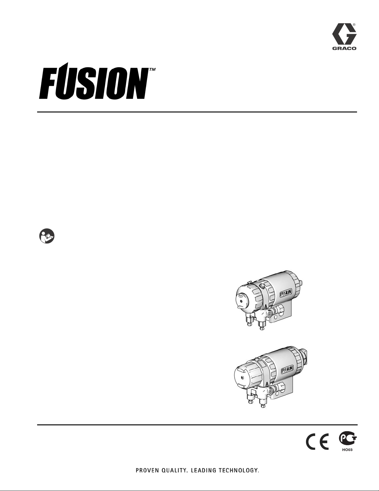
Automatic Plural Component, Impingement
Mix Spray Gun
For use with non-flammable foam and polyurea.
Not for use in explosive atmospheres.
3500 psi (24.2 MPa, 242 bar) Maximum Fluid Working Pressure
80-130 psi (0.55-0.9 MPa, 5.5-9.1 bar) Air Inlet Pressure Range
200°F (94°C) Maximum Fluid Temperature
EN
Important Safety Instructions
Read all warnings and instructions in this manual.
Save these instructions.
Air Purge Gun
For model information and related manuals, see page 3.
Mechanical Purge Gun
For model information and related manuals, see page 4.
US Patent No. D479,305
Korean Patent No. 338185
Australian Patent No. 152610
ROC Patent No. I288661
Chinese Patent No. ZL200380101833
Japanese Patent No. 4331721
TI4524b
TI4525b
Page 2
Contents
Contents
Manual Conventions . . . . . . . . . . . . . . . . . . . . . . . . 2
Air Purge Guns . . . . . . . . . . . . . . . . . . . . . . . . . . . . 3
Round Pattern Guns . . . . . . . . . . . . . . . . . . . . . . 3
Flat Pattern Guns . . . . . . . . . . . . . . . . . . . . . . . . 3
Related Manuals . . . . . . . . . . . . . . . . . . . . . . . . . 3
Mechanical Purge Guns . . . . . . . . . . . . . . . . . . . . . 4
Standard Round Pattern Guns . . . . . . . . . . . . . . 4
Direct Impingement Round Pattern Guns . . . . . . 4
Direct Impingement Flat Pattern Guns . . . . . . . . 4
Related Manuals . . . . . . . . . . . . . . . . . . . . . . . . . 4
Warning . . . . . . . . . . . . . . . . . . . . . . . . . . . . . . . . . . . 5
Isocyanate Hazard Keep A and B Components
Separate . . . . . . . . . . . . . . . . . . . . . . . . . . . . . . . 6
Grounding . . . . . . . . . . . . . . . . . . . . . . . . . . . . . . . . 7
Piston Safety Lock . . . . . . . . . . . . . . . . . . . . . . . . . 7
Turning Air Cap . . . . . . . . . . . . . . . . . . . . . . . . . . . . 7
Manual Conventions
Warning
Loss of Air Pressure . . . . . . . . . . . . . . . . . . . . . . . . 7
Overall View . . . . . . . . . . . . . . . . . . . . . . . . . . . . . . . 8
Installation . . . . . . . . . . . . . . . . . . . . . . . . . . . . . . . . 9
Mounting gun to rod . . . . . . . . . . . . . . . . . . . . . . . 9
Mounting gun to stationary support or robot arm 9
Connecting airline and accessories . . . . . . . . . . 10
Setup . . . . . . . . . . . . . . . . . . . . . . . . . . . . . . . . . . . . 11
Pressure Relief Procedure . . . . . . . . . . . . . . . . . . 13
Shutdown . . . . . . . . . . . . . . . . . . . . . . . . . . . . . . . . 14
Parts . . . . . . . . . . . . . . . . . . . . . . . . . . . . . . . . . . . . 16
Air Purge Gun . . . . . . . . . . . . . . . . . . . . . . . . . . 16
Mechanical Purge Gun . . . . . . . . . . . . . . . . . . . 18
Mounting Dimensions . . . . . . . . . . . . . . . . . . . . . . 20
Technical Data . . . . . . . . . . . . . . . . . . . . . . . . . . . . 21
Accessories . . . . . . . . . . . . . . . . . . . . . . . . . . . . . . 21
Graco Standard Warranty . . . . . . . . . . . . . . . . . . . 22
Graco Information . . . . . . . . . . . . . . . . . . . . . . . . . 22
A warning alerts you to possible serious injury or
death if you do not follow instructions.
Symbols, such as fluid injection (shown), alert you to a
specific hazard and direct you to read the indicated
hazard warnings on pages 5-6.
Caution
CAUTION
A caution alerts you to possible equipment damage or
destruction if you do not follow instructions.
Note
A note indicates additional helpful information.
2 310649C
Page 3

Air Purge Guns
Round Pattern Guns
Mix Chamber
Impingement
Gun Part
No., Series Part No.
248376, A AR2929 .029 (0.70) -00
248377, A AR4242 .042 (1.00) -01
248378, A AR5252 .052 (1.30) -02
248379, A AR6060 .060 (1.50) -03
Flat Pattern Guns
Port Size
in (mm)
Equivalent
Air Purge Guns
Size
Mix Chamber Flat Tip
Impingement
Gun Part
No., Series Part No.
248380, A AF2020 .020 (0.50) -000 FT0424 8-10 (203-254) .024 (0.61)
248381, A AF2929 .029 (0.70) -00 FT0438 8-10 (203-254) .038 (0.97)
Port Size
in. (mm)
Equivalent
Size Part No.
Pattern Size
in. (mm)
Orifice Size
in. (mm)
Related Manuals
For complete safety, operation, and repair information, refer to the applicable manual listed below.
Fusion Air Purge Spray Gun
Part No. Description
309550 Instruction-Parts Manual (English)
310649C 3
Page 4

Mechanical Purge Guns
Mechanical Purge Guns
Use only these mix module/tip combinations.
Standard Round Pattern Guns
Gun Part No., Series Slip-Fit™ Polycarballoy™ Mix Module Part No.,
see manual 309856 for numbering code
248386, A MR3535 RTM040
248387, A MR5757 RTM070
see manual 309856 for numbering code
Direct Impingement Round Pattern Guns
Gun Part No., Series Slip-Fit™ Polycarballoy™ Mix Module Part No.,
see manual 309856 for numbering code
248382, A XR2929 RTM040
248383, A XR3535 RTM040
see manual 309856 for numbering code
Direct Impingement Flat Pattern Guns
Gun Part No., Series Slip-Fit™ Polycarballoy™ Mix Module Part No.,
see manual 309856 for numbering code
248384, A XF1313 FTM317
248385, A XF1818 FTM424
see manual 309856 for numbering code
Round CeramTip™ Part No.,
Round CeramTip™ Part No.,
Flat CeramTip™ Part No.,
Related Manuals
For complete safety, operation, and repair information, refer to the applicable manual listed below.
Fusion Mechanical Purge Spray Gun
Part No. Description
309856 Instruction-Parts Manual (English)
4 310649C
Page 5
Warning
WARNING
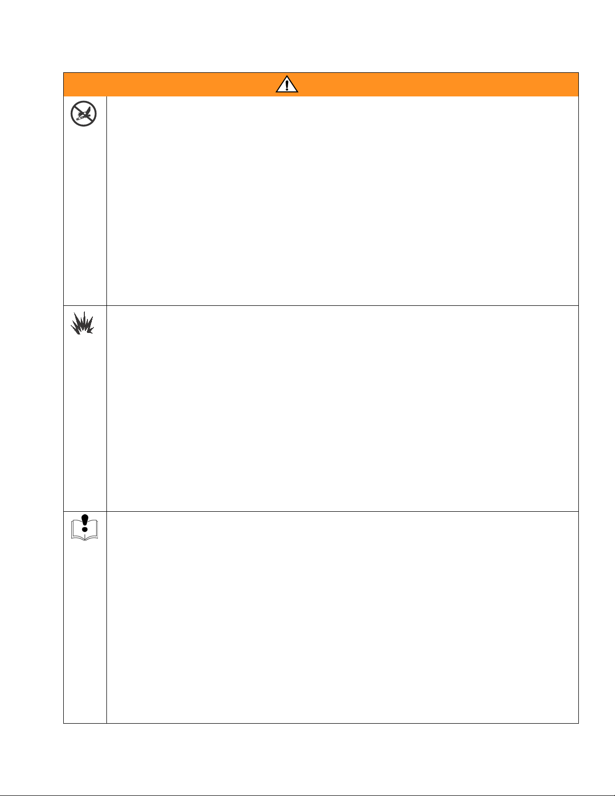
SKIN INJECTION HAZARD
High-pressure fluid from gun, hose leaks, or ruptured components will pierce skin. This may look like just
a cut, but it is a serious injury that can result in amputation. Get immediate surgical treatment.
• Do not point the gun at anyone or at any part of the body.
• Do not put your hand or fingers over the gun fluid nozzle.
• Do not stop or deflect leaks with your hand, body, glove, or rag.
• Do not “blow back” fluid; this is not an air spray system.
• Follow Pressure Relief Procedure, page 13, when you stop spraying and before cleaning, check-
ing, or servicing equipment.
• Use lowest possible pressure when flushing, priming, or troubleshooting.
• Engage piston safety lock when not spraying.
• Tighten all fluid connections before operating the equipment.
• Check hoses, tubes, and couplings daily. Replace worn or damaged parts immediately. High pressure hose cannot be recoupled; replace the entire hose.
FIRE AND EXPLOSION HAZARD
Flammable fumes, such as solvent and paint fumes, in work area can ignite or explode. To help prevent
fire and explosion:
• Use equipment only in well ventilated area.
• Eliminate all ignition sources, such as pilot lights, cigarettes, portable electric lamps, and plastic drop
cloths (potential static arc).
• Do not plug or unplug power cords or turn lights on or off when flammable fumes are present.
• Keep the work area free of debris, including solvent, rags, and gasoline.
• Ground equipment and conductive objects. See Grounding in Fusion Gun manual 309550 or
309856.
• Hold gun firmly to side of grounded pail when actuating into pail.
• Use only grounded hoses.
• If there is static sparking or you feel a shock, stop operation immediately. Do not use equipment
until you identify and correct the problem.
EQUIPMENT MISUSE HAZARD
Misuse can cause serious injury or death.
• For professional use only.
• Use equipment only for its intended purpose. Call your Graco distributor for information.
• Read manuals, warnings, tags, and labels before operating equipment. Follow instructions.
• Check equipment daily. Repair or replace worn or damaged parts immediately.
• Do not alter or modify equipment. Use only Graco parts and accessories.
• Do not exceed the maximum working pressure or temperature rating of the lowest rated system
component. See Technical Data in all equipment manuals.
• Use fluids and solvents that are compatible with equipment wetted parts. See Technical Data in all
equipment manuals. Read fluid and solvent manufacturer’s warnings.
• Route hoses and cables away from traffic areas, sharp edges, moving parts, and hot surfaces.
• Do not use hoses to pull equipment.
• Comply with all applicable safety regulations.
310649C 5
Page 6
Isocyanate Hazard Keep A and B Components Separate
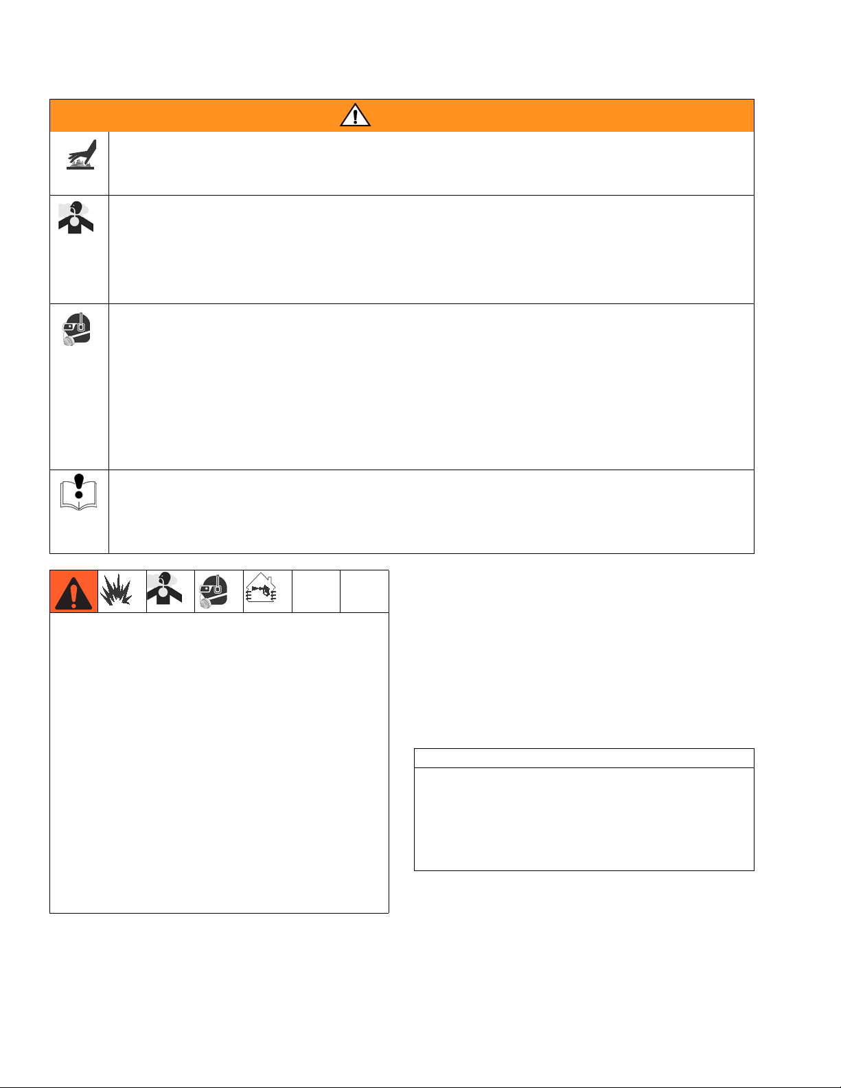
BURN HAZARD
Equipment surfaces and fluid that’s heated can become very hot during operation. To avoid severe
burns, do not touch hot fluid or equipment. Wait until equipment/fluid has cooled completely.
TOXIC FLUID OR FUMES HAZARD
Toxic fluids or fumes can cause serious injury or death if splashed in the eyes or on skin, inhaled, or
swallowed.
• Read Material Safety Data Sheet (MSDS) to know the specific hazards of the fluids you are using.
• Store hazardous fluid in approved containers, and dispose of it according to applicable guidelines.
PERSONAL PROTECTIVE EQUIPMENT
You must wear proper protective equipment when operating, servicing, or when in the operating area of
the equipment to help protect you from serious injury, including eye injury, inhalation of toxic fumes,
burns, and hearing loss. This equipment includes but is not limited to:
• Protective eyewear
• Clothing and respirator as recommended by the fluid and solvent manufacturer
•Gloves
• Hearing protection.
WARNING
PRESSURIZED ALUMINUM PARTS HAZARD
Do not use 1,1,1-trichloroethane, methylene chloride, other halogenated hydrocarbon solvents or fluids
containing such solvents in pressurized aluminum equipment. Such use can cause serious chemical
reaction and equipment rupture, and result in death, serious injury, and property damage.
Spraying materials containing isocyanates creates
potentially harmful mists, vapors, and atomized particulates.
Read material manufacturer’s warnings and material
MSDS to know specific hazards and precautions
related to isocyanates.
Prevent inhalation of isocyanate mists, vapors, and
atomized particulates by providing sufficient ventilation in the work area. If sufficient ventilation is not
available, a supplied-air respirator is required for
everyone in the work area.
To prevent contact with isocyanates, appropriate personal protective equipment, including chemically
impermeable gloves, boots, aprons, and goggles, is
also required for everyone in the work area.
Isocyanate Hazard
Keep A and B
Components
Separate
CAUTION
To prevent cross-contamination of the gun’s wetted
parts, do not interchange A component (isocyanate)
and B component (resin) parts. The gun is shipped
with the A side on the left. The fluid manifold, fluid
housing, side seal cartridge, check valve cartridge,
and mix chamber are marked on the A side.
6 310649C
Page 7
Grounding
Grounding
Check your local electrical code and proportioner manual for detailed grounding instructions.
Ground the spray gun through connection to a
Graco-approved grounded fluid supply hose.
Piston Safety Lock
Engage piston safety lock whenever you stop spraying, to avoid accidental triggering.
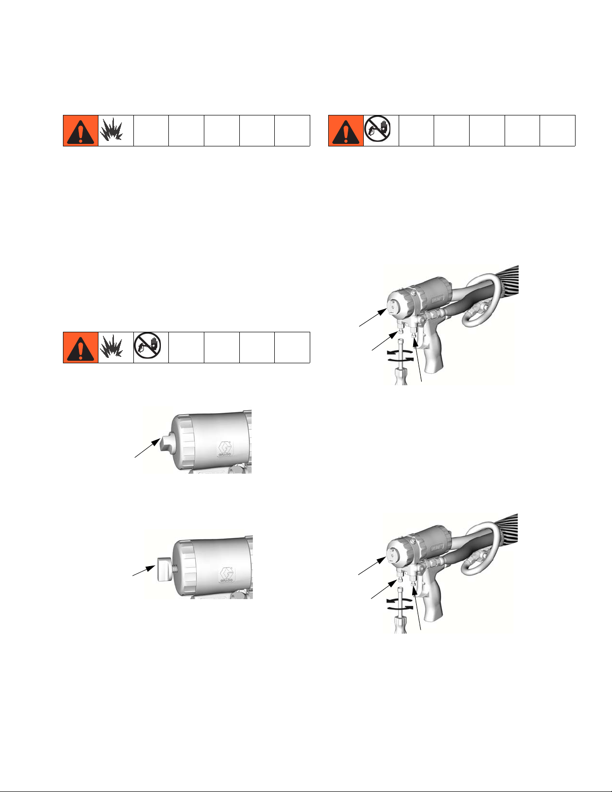
Turning Air Cap
1. Follow Pressure Relief Procedure, page 15.
2. Close fluid valves A and B before turning air cap
(C).
C
B
To engage piston safety lock: push knob in and turn
clockwise. If engaged, gun will not actuate.
Engaged
To disengage piston safety lock: push knob in and
turn counterclockwise until it pops out. There will be a
gap between knob and gun body.
Disengaged
TI2409A
TI2410A
TI2421A
A
Loss of Air Pressure
In event of loss of air pressure, gun will continue to
spray. To shut off gun, do one of the following:
• Push in piston safety lock, see page 10.
• Close fluid valves A and B.
C
B
TI2421A
A
310649C 7
Page 8

Overall View
Overall View
Mechanical Purge Gun Shown
C
H
E
F
K
G
D
M
L
TI4525b
M
J
B
Key:
A A Side Fluid Valve (ISO)
B B Side Fluid Valve (RESIN)
CAir Cap
D Fluid Housing
E Gun Fluid Manifold
F Cleanoff Air Valve
G Piston Safety Lock
H CeramTip (behind air cap)
J Optional Fluid Inlets (A Side Shown)
K Lock Ring
L Fluid Inlet Swivels (A Side Shown)
M Optional Air Inlets (A Side Shown)
A
8 310649C
Page 9

Installation
Mounting gun to rod
1. To mount the gun on a 1/2 in. diameter rod, insert
the bar (A) through the hole in the gun body as
shown.
Installation
ti4750a
2. Secure the gun to the bar by tightening 1/4 in. - 20
mounting screws.
Mounting gun to stationary support or robot arm
To mount gun to stationary support or robot arm, see
mounting hole dimensions page 20.
Two .1 28 in .
alignment
pin holes
Two 1/4 20 unc
holes
ti4751b
310649C 9
Page 10

Installation
Connecting airline and accessories
1. On each gun air supply line, install an air pressure
regulator.
• It is recommended that the tip clean off air, gun
actuation, and gun deactuation air be supplied
and regulated separately.
• A minimum of 80 psi (.55 mpa, 5.5 bar) air pressure must be supplied to the gun for proper
operation.
• A three-way air valve, which exhausts cylinder
air, is required.
2. On each gun air supply line, install a bleed-type air
shut off valve down stream of the gun air regulator.
3. On the main air line, install a bleed-type air shut off
valve.
Clean off air
Three 1/8 in. 27 npt ports
(air inlet)
Gun
actuation
Gun
deactuation
ti4751b
10 310649C
Page 11

Setup
Setup
1. Close fluid valves A and B.
TI2411A
2. Connect A (ISO) and B (RESIN) fluid hoses to fluid
manifold.
B (RESIN)
TI2417A
A (ISO)
5. For Mechanical Purge Guns Only:
a. Open clean off air line valve. Air should
flow from air cap around Ceram Tip (M).
b. Open clean off air valve (K) about 1/4 to
1/2 turn, then adjust air flow as required.
c. Adjust purge rod, see manual 309856.
d. Go to step 10.
K
M
TI4765A
For Air Purge Guns Only:
3. Engage piston safety lock.
TI3850a
4. Connect the airlines, see Installation page 8.
Attach fluid manifold (D) to gun.
M
TI4764A
To change position of fluid manifold or use
optional fluid inlets, see Fusion Gun manual
309856 or 309550.
a. Open clean off air line valve. Air should flow from
nozzle (N). Continue through steps below.
N
6. Disengage piston safety lock.
TI4766A
310649C 11
Page 12

Setup
7. Actuate gun to check for full mix chamber travel.
Front of air cap (C) should be approximately flush
with front retaining ring (U).
U
C
TI4766a
11. Open B (RESIN) fluid valve (about three half
turns). Then open A (ISO) fluid valve.
8. Open cleanoff air valve (K) 1/4-1/2 turn and
actuate air line to check that cleanoff air is flowing.
Adjust as desired.
K
9. Engage piston safety lock.
TI2409A
10. Turn on proportioner.
TI4752A
12. Disengage piston safety lock.
TI3849
13. Test spray onto card board. Adjust pressure and
temperature to get desired results.
TI4763A
14. Apply layer of lubricant over front of gun and
lock ring, or use gun cover to prevent overspray
buildup and ease disassembly. See Fusion Gun
Manual 309856 or 309550 to order lubricant and
gun cover
15. Gun is ready to spray.
CAUTION
Air supply is required for gun actuation. Do not disconnect gun air supply until fluid pressure is relieved,
see page 13.
12 310649C
Page 13

Pressure Relief Procedure
4. Actuate gun onto cardboard or into waste con-
tainer to relieve pressure.
Read warnings, page 5. Relieve pressure before
cleaning or repairing gun.
1. Engage piston safety lock.
Pressure Relief Procedure
TI4753a
TI3850A
CAUTION
Air supply is required for gun actuation. Do not disconnect gun air supply until fluid pressure is relieved.
2. Close fluid valves A and B. Leave air inlet (W)
open.
B
TI4752A
A
3. Disengage piston safety lock.
5. Engage piston safety lock.
TI3850A
Fluid in the hose and proportioner is still under pressure. Follow the Pressure Relief Procedure in the proportioner manual.
To relieve pressure in the hose after the gun is
removed, place the fluid manifold over containers, facing away from you. Very carefully open the fluid
valves. Under high pressure, fluid will spray sideways
from the fluid ports.
TI3849A
310649C 13
TI2484A
Page 14

Shutdown
Shutdown
For complete shutdown procedure, refer to Fusion Gun
manual 309550 or 309856.
14 310649C
Page 15

Shutdown
310649C 15
Page 16

Parts
Parts
Air Purge Gun
Round Pattern Gun Shown
Flat Pattern Detail
10 39
40
*‡24
‡18; see
detail at right
†*
‡11
19
TI2557A
*17
‡37
4
‡25
4
‡8
15
28
*16
27‡
‡
7
‡18; see detail
at right
14
21‡*
61
5
19
24
61
30
4
4
Check Valve (26)
Detail
‡†26b
‡
‡26d
‡*26g
1
‡†26a
61
*‡26f
Seal Cartridge (18) Detail
26e
‡26c
TI3927A
‡*
‡10
‡9
see detail
3‡
‡26;
23
12e
3
12c
50
12f
3
3
*‡18e
*‡†18c
‡18b
*‡18d
‡†18a
TI3926A
at right
12b
12a‡
5
Supplied Tools
12d
3
Torque to 235-245 in-lb (26.6-27.7 N•m).
4
Torque to 35-45 in-lb (4-5 N•m).
5
Torque to 32-40 ft-lb (43-54 N•m).
16 310649C
12g
TI4521b
53
43
54
TI3870A
Page 17

Parts
Ref.
No. Part No. Description Qty
1 16H889 BODY, air purge 1
3
‡ 248137 O-RING; PTFE; package of 6 1
4
15B206 LOCK, safety 1
5
15B204 CAP, cylinder 1
7
‡ 15B215 RING, lock 1
8
‡ 15B223 VALVE, cleanoff air 1
9
‡ 15B211 RING, retaining 1
10‡ 15B210 AIR CAP; for round pattern guns 1
15B801 AIR CAP; for flat pattern guns;
1
not included in Front End Replacement Kit 246361
‡ 246491 HOUSING, fluid 1
11
12 246012 MANIFOLD, fluid;
1
includes 12a-12g
12a
† .MANIFOLD 1
12b 246356 . VALVE, fluid 2
12c 100139 . PLUG, pipe; 1/8-27 npt 2
12d 15B221 . BOLT; 5/16-24 1
12e 117634 . SWIVEL, B side; 1/8 npt(m) x
1
no. 6 JIC(f)
12f 117635 . SWIVEL, A side; 1/8 npt(m) x
1
no. 5 JIC(f)
12g 15B993 . SPRING, ring, lock 1
14*
248136 O-RING, cylinder cap;
1
package of 6
15 15B203 PISTON 1
16* 248135 O-RING, piston; package of 6 1
17* 248134 O-RING, piston shaft;
1
package of 6
18
‡ 246349 CARTRIDGE, seal, A side;
1
includes 18a-18e
246350 CARTRIDGE, seal, B side;
1
includes 18a-18e
18a
† . CARTRIDGE BODY 1
18b 117491 . SPRING 1
18c*
† 246348 . SEAL KIT 1
18d* 248130 . O-RING, cartridge body;
1
package of 6
18e* 248128 . O-RING, side seal; package of 6 1
19 CHAMBER, mix, see page 3 1
21
‡* 248132 O-RING; package of 6 1
‡* 248131 O-RING; package of 6 1
23
24
‡* 246354 O-RING; package of 6 1
25
‡ 100846 FITTING, grease 1
‡ 246731 VALVE, check, A side; includes
26
1
26a-26g
246352 VALVE, check, B side; includes
1
26a-26g
26a
‡† .HOUSING 1
26b
‡† 15B214 . SCREW; 5/16-18 x
1
1/2 in. (13 mm)
26c
‡ 104396 . BALL; carbide 1
26d
‡ . SCREEN; see below 1
26e‡ 117490 . SPRING 1
26f
‡* 248133 . O-RING, check valve face;
1
package of 6
26g
‡* 248129 . O-RING, check valve housing;
1
package of 6
Ref.
No. Part No. Description Qty
27‡ 116550 RING, retaining 1
28
15B205 STOP, piston 1
30
114070 SPRING 1
36 222385 CARD, warning; not shown 1
37
‡ 15B689 COVER, grease fitting 1
39 FTxxxx TIP, flat; see page 3 1
40* 246360 O-RING; PTFE; flat tip models
1
only; package of 3;
43 117661 VISE, pin; dual reversible chucks 1
46 117792 GREASE GUN; not shown 1
50 112307 ELBOW, street; 1/8 npt (m x f) 2
53 117642 NUT DRIVER, hex; 5/16 1
54 118575 SCREWDRIVER; 1/8 blade 1
55 172479 TAG, warning; not shown 1
57 117773 GREASE CARTRIDGE; 3 oz;
1
not shown; MSDS sheet available
at www.graco.com
58 197979 COVER, gun; not shown 1
59 118665 LUBRICANT, Fusion Gun; 4 oz
1
(113 gram)
61 100139 PLUG, 1/8 NPT 3
* These parts are only available in repair kits. To select
a kit, refer manual 309550.
† These parts are not available singly.
‡ These parts are included in Front End Replacement
Kit 246361.
These parts are included in Safety Stop Assembly
248064 (includes 1 of item 24).
Replacement Danger and Warning labels, tags, and
cards are available at no cost.
Available in 248279 Kit, package of 10.
Check Valve Filter Screen Kits (10 per kit)
80 mesh filter screen is standard with gun.
246357 40 mesh (.015 in., 375 micron)
246358 60 mesh (.010 in., 238 micron)
246359 80 mesh (.007 in., 175 micron)
310649C 17
Page 18

Parts
Mechanical Purge Gun
†‡ 25 39
46*
928
40
32
19
16* 8 31
14*
18
15
10 17 59
60
4
3
‡44
‡*24
†‡7
‡36;
see detail
at right
†12a
12b
3
12d
20
21*‡
46*†‡
12e
1
12c
12f
50
23‡
1
1
11‡
61
18
35
Check Valve (36)
Detail
‡
1
61
†‡36b
‡36e
‡36c
‡36d
*‡36g
†‡36a
61
*‡36f
TI3927A
Supplied Tools
53
12g
TI4523b
34
54
TI3870a
1
Torque to 125-135 in-lb (14-15 N•m).
3
Torque to 32-40 ft-lb (43-54 N•m).
18 310649C
Page 19

Parts
Ref.
No. Part No. Description Qty
1 15D919 BODY, mechanical purge 1
3
15C374 ACTUATOR; safety 1
4
15C390 BUSHING, safety 1
7
†‡ HOUSING, fluid 1
8 118145 SPRING, purge rod 1
9 15C375 AIR CAP 1
10
15C373 CAP, rear 1
11‡
12 246012 MANIFOLD, fluid;
15B215 RING, lock 1
1
includes 12a-12g
12a
† .MANIFOLD 1
12b 246356 . VALVE, fluid 2
12c 100139 . PLUG, pipe; 1/8-27 npt 2
12d 15B221 . BOLT; 5/16-24 1
12e 117634 . SWIVEL, B side; 1/8 npt(m) x
1
no. 6 JIC(f)
12f 117635 . SWIVEL, A side; 1/8 npt(m) x
1
no. 5 JIC(f)
12g 15B993 . SPRING, ring, lock 1
14*
248136 O-RING, rod stop; package of 6 1
15
15C372 STOP, purge rod 1
16* 248135 O-RING, piston; package of 6 1
17
118144 SPRING, piston safety lock 1
18
248095 O-RING, purge rod; package of 6 1
19 248096 O-RING, piston shaft;
1
package of 6
20 248138 O-RING, housing, small;
1
package of 6
21
‡* 248132 O-RING, housing, large;
1
package of 6
23
‡ 15C378 NUT, rod seal, rear 1
24‡* 246354 O-RING; package of 6 1
25 15C377 NUT, mix module 1
28 15C376 RETAINER, CeramTip 1
31 248001 ROD, purge; includes 1 of item 18 1
32 15C371 PISTON 1
34 117661 VISE, pin; dual reversible chucks 1
35
‡ 116550 RING, retaining 1
36
‡ 246731 VALVE, check, A side; includes
1
36a-36g
246352 VALVE, check, B side; includes
1
36a-36g
36a
‡† .HOUSING 1
36b
‡† 15B214 . SCREW; 5/16-18 x
1
1/2 in. (13 mm)
36c
‡ 104396 . BALL; carbide 1
36d
‡ . SCREEN; see below 1
‡ 117490 . SPRING 1
36e
36f
‡* 248133 . O-RING, check valve face;
1
package of 6
36g
‡* 248129 . O-RING, check valve housing;
1
package of 6
37 222385 TAG, warning; not shown 1
Ref.
No. Part No. Description Qty
39 MODULE, mix, see page 4 1
40 CeramTip; see page 4 1
44‡
46
15C382 VALVE, cleanoff air 1
†‡* 248003 SEAL KIT, purge rod; includes 4
1
seals
50 112307 ELBOW, street;1/8 npt (m x f) 2
53 117642 NUT DRIVER, hex; 5/16 1
54 118575 SCREWDRIVER; 1/8 blade 1
55 197979 COVER, gun; not shown 1
57 118665 LUBRICANT, Fusion Gun; 4 oz
1
(113 gram)
59
15D329 STOP, rod 1
60 115452 RING, retaining 1
61 100139 PLUG, 1/8 NPT 3
* These parts are only available in repair kits. To select
a kit, refer to Gun Repair Kits in manual 309856.
† These parts are not available singly.
‡ These parts are included in Fluid Housing Assembly
Kit 248004 (includes 1 of items 24 and 46).
These parts are included in Safety Stop Assembly
248028 (includes 1 of item 18).
Replacement Danger and Warning labels, tags, and
cards are available at no cost.
Available in 248279 Kit, package of 10.
Check Valve Filter Screen Kits (10 per kit)
80 mesh filter screen is standard with gun.
246357 40 mesh (.015 in., 375 micron)
246358 60 mesh (.010 in., 238 micron)
246359 80 mesh (.007 in., 175 micron)
310649C 19
Page 20

Mounting Dimensions
Mounting Dimensions
Gun mounting plate dimensions
in. (mm)
1.30 (33.0)
0.625 (15.88)
1.06 (26.92)
0.73
(18.54)
2 x 1/4-20
1 (25.4)
F
IG. 1
4 x M5
3 x 1/8 npt
2 x ⌀ 0.127 (3.23)
ti4751b
0.625
(15.88)
20 310649C
Page 21

Technical Data
Category Data
Maximum Fluid Working Pressure 3500 psi (24.2 MPa, 242 bar)
Minimum Air Inlet Pressure 80 psi (0.55 MPa, 5.5 bar)
Maximum Air Inlet Pressure 130 psi (0.9 MPa, 9 bar)
Air Flow Range at 100 psi (0.7 MPa, 7 bar)
Maximum Fluid Temperature 200° F (94° C)
Air Inlet Size 1/8 - 27 NPT
A Component (ISO) Inlet Size -5 JIC; 1/2-20 UNF
B Component (Resin) Inlet Size -6 JIC; 9/16-18 UNF
Sound Pressure 70 dB(A), at 100 psi (0.7 MPa, 7 bar)
Sound Power, measured per ISO 9416-2 79.9 dB(A), at 100 psi (0.7 MPa, 7 bar)
Length 7.6 in. (193 mm)
Height 3.75 in. (95 mm)
Width 3.1 in. (79 mm)
Weight
Wetted Parts
0.9-8.8 scfm (.03-0.25 m
Air Purge Guns: 2.35 lb (1.06 kg)
Mechanical Purge Guns: 2.75 lb (1.24 kg)
Aluminum, stainless steel, carbon steel, chemically resistant o-rings,
ultra-high molecular weight polyethylene (UHMWPE), brass,
Polycarballoy™
3
/min)
Technical Data
All brand names or marks are used for identification purposes and are trademarks of Graco Inc. or their respective
owners.
Accessories
Part No. Description
115807 SOLENOID, 24 VDC, 4-way
310649C 21
Page 22

Graco Standard Warranty
Graco warrants all equipment referenced in this document which is manufactured by Graco and bearing its name to be free from defects in
material and workmanship on the date of sale to the original purchaser for use. With the exception of any special, extended, or limited warranty
published by Graco, Graco will, for a period of twelve months from the date of sale, repair or replace any part of the equipment determined by
Graco to be defective. This warranty applies only when the equipment is installed, operated and maintained in accordance with Graco’s written
recommendations.
This warranty does not cover, and Graco shall not be liable for general wear and tear, or any malfunction, damage or wear caused by faulty
installation, misapplication, abrasion, corrosion, inadequate or improper maintenance, negligence, accident, tampering, or substitution of
non-Graco component parts. Nor shall Graco be liable for malfunction, damage or wear caused by the incompatibility of Graco equipment with
structures, accessories, equipment or materials not supplied by Graco, or the improper design, manufacture, installation, operation or
maintenance of structures, accessories, equipment or materials not supplied by Graco.
This warranty is conditioned upon the prepaid return of the equipment claimed to be defective to an authorized Graco distributor for verification of
the claimed defect. If the claimed defect is verified, Graco will repair or replace free of charge any defective parts. The equipment will be returned
to the original purchaser transportation prepaid. If inspection of the equipment does not disclose any defect in material or workmanship, repairs will
be made at a reasonable charge, which charges may include the costs of parts, labor, and transportation.
THIS WARRANTY IS EXCLUSIVE, AND IS IN LIEU OF ANY OTHER WARRANTIES, EXPRESS OR IMPLIED, INCLUDING BUT NOT LIMITED
TO WARRANTY OF MERCHANTABILITY OR WARRANTY OF FITNESS FOR A PARTICULAR PURPOSE.
Graco’s sole obligation and buyer’s sole remedy for any breach of warranty shall be as set forth above. The buyer agrees that no other remedy
(including, but not limited to, incidental or consequential damages for lost profits, lost sales, injury to person or property, or any other incidental or
consequential loss) shall be available. Any action for breach of warranty must be brought within two (2) years of the date of sale.
GRACO MAKES NO WARRANTY, AND DISCLAIMS ALL IMPLIED WARRANTIES OF MERCHANTABILITY AND FITNESS FOR A
PARTICULAR PURPOSE, IN CONNECTION WITH ACCESSORIES, EQUIPMENT, MATERIALS OR COMPONENTS SOLD BUT NOT
MANUFACTURED BY GRACO. These items sold, but not manufactured by Graco (such as electric motors, switches, hose, etc.), are subject to
the warranty, if any, of their manufacturer. Graco will provide purchaser with reasonable assistance in making any claim for breach of these
warranties.
In no event will Graco be liable for indirect, incidental, special or consequential damages resulting from Graco supplying equipment hereunder, or
the furnishing, performance, or use of any products or other goods sold hereto, whether due to a breach of contract, breach of warranty, the
negligence of Graco, or otherwise.
FOR GRACO CANADA CUSTOMERS
The Parties acknowledge that they have required that the present document, as well as all documents, notices and legal proceedings entered into,
given or instituted pursuant hereto or relating directly or indirectly hereto, be drawn up in English. Les parties reconnaissent avoir convenu que la
rédaction du présente document sera en Anglais, ainsi que tous documents, avis et procédures judiciaires exécutés, donnés ou intentés, à la suite
de ou en rapport, directement ou indirectement, avec les procédures concernées.
Graco Information
For the latest information about Graco products, visit www.graco.com.
TO PLACE AN ORDER, contact your Graco distributor, or call this number to identify the distributor closest to you:
1-800-328-0211 Toll Free
612-623-6921
612-378-3505 Fax
All written and visual data contained in this document reflects the latest product information available at the time of publication.
GRACO INC. AND SUBSIDIARIES • P.O. BOX 1441 • MINNEAPOLIS MN 55440-1441 • USA
Copyright 2004, Graco Inc. All Graco manufacturing locations are registered to ISO 9001.
Graco reserves the right to make changes at any time without notice.
Original instructions. This manual contains English. MM 310649
Graco Headquarters: Minneapolis
International Offices: Belgium, China, Japan, Korea
www.graco.com
Revised 09/2011
 Loading...