

Page 1
Instructions - Parts List
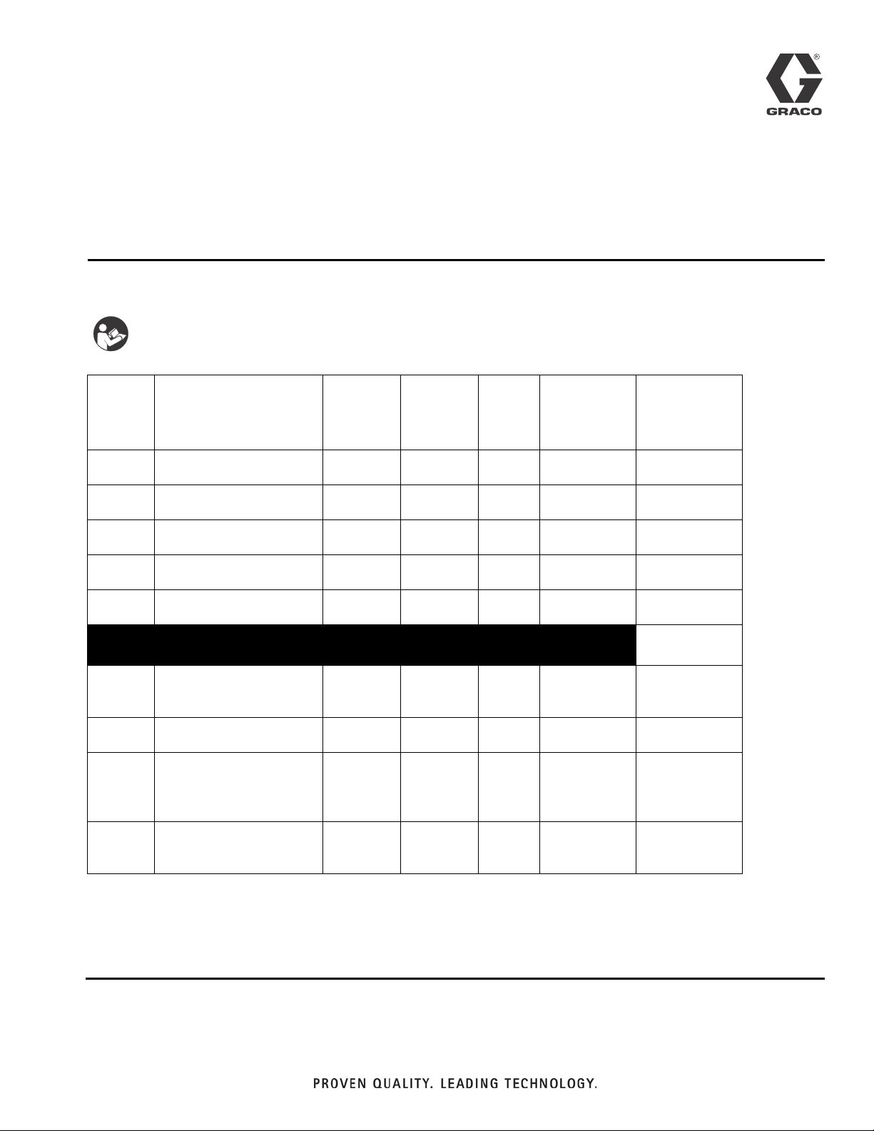
Air Regulators
Important Safety Instructions.
Read all warnings and instructions in this manual.
Save these instructions.
Part No. Description Inlet Outlets Handle
234389 Air Regulator with gauge,
self relieving
234434 Air Regulator with gauge,
self relieving
234390 Mini Air Regulator with
gauge
24H419 Mini Air Regulator with
gauge
24H420 Mini Air Regulator with
gauge
234391 Air Regulator with
2 regulated outlets,
1 unregulated outlet
234392 Air Regulator with
3 regulated outlets
234393 Air Regulator 234391 with
gauge and shutoff valve,
1 regulated outlet,
1 unregulated outlet
234394 Air Regulator 234392 with
gauge and shutoff valve,
2 regulated outlets
1/4 in.
npt(m)
1/4 in.
npt(m)
1/4 in.
npt(f)
1/4 in.
BSP(f)
1/4 in.
npt(f)
3/8 in.
npt(f)
3/8 in.
npt(f)
3/8 in.
npt(m)
3/8 in.
npt(m)
1/4 in.
npt(f)
1/4 in.
npt(f)
1/4 in.
npt(f)
3/8 in.
BSP(f)
3/8 in.
npt(f)
1/4 in.
npt(f)
1/4 in.
npt(f)
1/4 in.
npt(f)
1/4 in.
npt(f)
knob 160(1.1, 11) 22 CFM
knob 160(1.1, 11) 35 CFM
knob 160(1.1, 11) 22 CFM
Knob 150(1.0, 10) 22 CFM
Knob 150(1.0, 10) 22 CFM
tee 175(1.2, 12) 50 CFM
tee 175(1.2, 12) 50 CFM
tee 160(1.1, 11) 50 CFM
tee 160(1.1, 11) 50 CFM
Maximum
Inlet
Pressure
psi (MPa, bar)
309924H
ENG
Maximum CFM
at 50 psi (.34
MPa, 3.4 bar
at 100 psi (0.7
MPa, 7 bar
Page 2
Installation
Installation
Before installing air line components, blow out the pipe
line to remove debris. Be sure air to the regulator is
clean. Erratic operation or loss of regulation is usually
Use pipe compound or tape sparingly and only on male
threads. Locate the regulator as close as possible to the
equipment it serves.
caused by dirt in the regulator.
Install a main air shutoff valve upstream from the air
controls to isolate them for service.
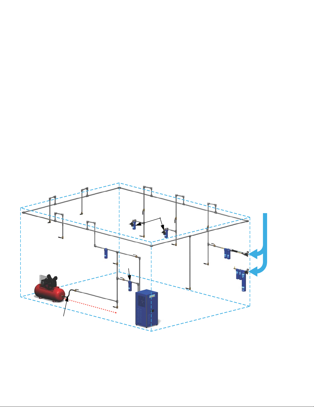
Shop Air Piping Layout
NOTE:
• Main Air Line stand pipe should not be smaller than compressor outlet size.
• A minimum of 25 ft (7.62 m) from compressor to first filter outlet is required to cool air [50 ft. (15.24 m) optimum].
S
l
o
Main air line
3/4 in. (19 mm) minimum
1-1/4 in. (32 mm) optimum
1/2 in.
(13 mm)
drops
p
e
s
R
e
c
o
m
5
Air control
unit or air
filter
m
0
f
t
(
1
5
d
o
w
n
a
n
d
a
e
n
d
.
2
4
m
w
a
e
d
)
g
y
a
.
4
i
n
.
(
1
1
7
l
v
a
m
m
n
i
z
e
)
d
r
d
p
o
p
i
i
p
e
.
n
Membrane or
desiccant air
drying system
Compressor
Flexible hose
between compressor
and stand pipe
Coalescer
Main air
shutoff valve
1
5
-
2
0
f
t
(
4
,
6
Ball valve
Drain leg
Air filter
-
6
,
1
m
)
Drain valve
2 309924H
Page 3
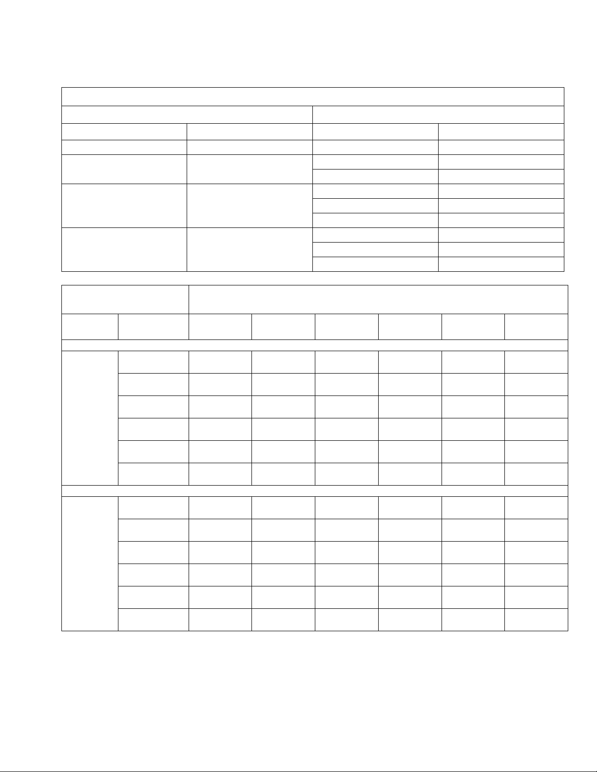
Compressor Main Air Line
HP CFM Length ft (m) Size in. (mm)
1-1/2 - 2 6 - 9 any 3/4 (19)
3 - 5 12 - 20
5 - 10 20 - 40
10 - 15 40 - 60
Inlet
Pressure
Air Hose ID 1/4 in. (6.4 mm)
40 (276, 2.8) 6 (41, .4)
50 (345, 3.4) 7.5 (52, .5)
psi (kPa, bar)
3
SCFM (ft
/min)
Air Hose ID 5/16 in. (7.9 mm)
psi (kPa, bar)
3
SCFM (ft
/min)
60 (414, 4.1) 9 (62, .6)
70 (483, 4.8) 10.75 (74, .7)2214.5 (100, 1)1617 (117, 1.2)1419.5 (134, 1.3)1322.5 (155, 1.6)1234 (234, 2.3)
80 (552, 5.5) 12.25 (84, .8)2516.5 (114,1.1)1819.5 (134, 1.3)1622.5 (155, 1.6)1525.5 (176, 1.8)1437 (255, 2.6)
90 (621, 6.2) 14 (97, 1)2818.75 (129, 1.3)2022 (152, 1.5)1725.25 (172, 1.7)1629 (200, 2)1539.5 (169, 2.7)
40 (276, 2.8)
50 (345, 3.4)
60 (414, 4.1)
70 (483, 4.8)
80 (552, 5.5)
90 (621, 6.2)
Minimum Pipe Size Recommendations
Up to 200 (61) 3/4 (19)
Over 200 (61) 1 (25.4)
Up to 100 (30.5) 3/4 (19)
Over100-200 (30.5-61) 1 (25.4)
Over 200 (61) 1-1/4 (31.8)
Up to 100 (30.5) 3/4 (19)
Over100-200 (30.5-61) 1-1/4 (31.8)
Over 200 (61) 1-1/2 (38.1)
Air Pressure Drop Through Hose, by Hose Length and ID
Temperature = 68° F
4 ft
(1.22 m)
14
17
20
2.25 (16, .2)
15
3 (21, .2)
19
3.75 (26, .3)
22
4.5(31, .3)
26
5.5 (38, .4)
30
6.5 (45, .4)
34
10 ft
(3.05 m)
8 (55, .6)
10
10 (69, .7)
12
12.5 (86, .9)1414.5 (100, .1)1216.75 (115,1.2)1119 (131, 1.3)1131 (214, 2.1)
2.75 (19, .2)
10
3.5 (24, .2)
12
4.5 (31, .3)
15
5.25 (36, .4)
17
6.25 (43, .4)
19
7.5 (52, .5)
22
15 ft
(4.6 m)
9.5 (66, .7)
9
12 (83, .8)
11
3.25 (22, .2)
9
4 (28, .3)
11
5 (34, .3)
13
6 (41, .4)
15
7 (48, .5)
17
8.5 (59, .6)
19
(6.1 m)
11 (76, .8)
14 (97, 1)
3.5 (24, .2)
4.5 (31, .3)
5.5 (38, .4)
6.75 (47, .5)
8 (55, .6)
9.5 (66, .7)
20 ft
8
10
8
10
11
13
15
17
Installation
25 ft
(7.62 m)
12.75 (88, 0.9)824 (165, 1.7)
16 (110, 1.1)928 (193, 1.9)
4 (28, .3)
8
5 (34, .3)
9
6 (41, .4)
11
7.25 (50, .5)
12
8.75 (60, .6)
14
10.5 (72, .7)
16
50 ft
(15.24 m)
8
9
10
11
12
12
8.5 (59, .6)
8
10 (69, .7)
9
11.5 (79, .8)
10
13 (90, .9)
12
14.5 (100, 1)
13
16 (110, 1.1)
14
309924H 3
Page 4

Repair
Pressure Adjustment
Do not exceed the Maximum Incoming Air Pressure of
the equipment. Over pressurizing can cause component rupture and serious injury.
Turn clockwise to increase air pressure. Turn counterclockwise to decrease air pressure.
NOTE: Push in the knob of Part No. 234389, 234390,
24H419, and 24H420 air regulators to lock their pressure setting.
Pressure Relief Procedure
To avoid injury, relieve air and fluid pressure before
checking, cleaning, or repairing the equipment.
Repair
1. Follow Pressure Relief Procedure, above.
2. Disassemble the regulator. Refer to Parts drawings.
3. Wash parts with household soap and water or denatured alcohol.
4. Wipe parts dry with a clean, soft, dry rag. Use compressed air to blow dirt and contaminants out of the
regulator body.
5. Inspect parts for wear or damage. Replace damaged parts.
6. Reassemble the regulator.
The following is a basic pressure relief procedure. Be
sure to follow the specific pressure relief procedure in
your spray gun and/or fluid supply equipment manuals.
1. Close the main air shutoff valve.
2. Trigger the gun or dispense valve and open any
drain valves to relieve pressure.
4 309924H
Page 5

Parts
Part No. 234389 and 234434 Part No. 234390
289163
289164
289168
119010
Parts
289163
288778
119077
288778 for 234434
or
156823 for 234389
289169
113911
156823
119077
Part No. 24H419 and 24H420
309924H 5
Page 6

Parts
Part No. 234393 (1 regulated, 1 unregulated outlet)
and 234394 (2 regulated outlets)
119285
289149
234391 for 234393
or
234392 for 234394
289165
Part No. 234391 (2 regulated, 1 unregulated outlet)
and 234392 (3 regulated outlets)
289159
289160
289151
289157
289156
289158
288780
289154
289152
288779
289153
289150
or
289166for 234392 /234394
*Repair Kit 289167 available for models 234391 & 234392.
for 234391/234393
289155
6 309924H
Page 7

Parts
309924H 7
Page 8

Graco Standard Warranty
Graco warrants all equipment referenced in this document which is manufactured by Graco and bearing its name to be free from defects in
material and workmanship on the date of sale to the original purchaser for use. With the exception of any special, extended, or limited warranty
published by Graco, Graco will, for a period of twelve months from the date of sale, repair or replace any part of the equipment determined by
Graco to be defective. This warranty applies only when the equipment is installed, operated and maintained in accordance with Graco’s written
recommendations.
This warranty does not cover, and Graco shall not be liable for general wear and tear, or any malfunction, damage or wear caused by faulty
installation, misapplication, abrasion, corrosion, inadequate or improper maintenance, negligence, accident, tampering, or substitution of
non-Graco component parts. Nor shall Graco be liable for malfunction, damage or wear caused by the incompatibility of Graco equipment with
structures, accessories, equipment or materials not supplied by Graco, or the improper design, manufacture, installation, operation or
maintenance of structures, accessories, equipment or materials not supplied by Graco.
This warranty is conditioned upon the prepaid return of the equipment claimed to be defective to an authorized Graco distributor for verification of
the claimed defect. If the claimed defect is verified, Graco will repair or replace free of charge any defective parts. The equipment will be returned
to the original purchaser transportation prepaid. If inspection of the equipment does not disclose any defect in material or workmanship, repairs will
be made at a reasonable charge, which charges may include the costs of parts, labor, and transportation.
THIS WARRANTY IS EXCLUSIVE, AND IS IN LIEU OF ANY OTHER WARRANTIES, EXPRESS OR IMPLIED, INCLUDING BUT NOT LIMITED
TO WARRANTY OF MERCHANTABILITY OR WARRANTY OF FITNESS FOR A PARTICULAR PURPOSE.
Graco’s sole obligation and buyer’s sole remedy for any breach of warranty shall be as set forth above. The buyer agrees that no other remedy
(including, but not limited to, incidental or consequential damages for lost profits, lost sales, injury to person or property, or any other incidental or
consequential loss) shall be available. Any action for breach of warranty must be brought within two (2) years of the date of sale.
GRACO MAKES NO WARRANTY, AND DISCLAIMS ALL IMPLIED WARRANTIES OF MERCHANTABILITY AND FITNESS FOR A
PARTICULAR PURPOSE, IN CONNECTION WITH ACCESSORIES, EQUIPMENT, MATERIALS OR COMPONENTS SOLD BUT NOT
MANUFACTURED BY GRACO. These items sold, but not manufactured by Graco (such as electric motors, switches, hose, etc.), are subject to
the warranty, if any, of their manufacturer. Graco will provide purchaser with reasonable assistance in making any claim for breach of these
warranties.
In no event will Graco be liable for indirect, incidental, special or consequential damages resulting from Graco supplying equipment hereunder, or
the furnishing, performance, or use of any products or other goods sold hereto, whether due to a breach of contract, breach of warranty, the
negligence of Graco, or otherwise.
FOR GRACO CANADA CUSTOMERS
The Parties acknowledge that they have required that the present document, as well as all documents, notices and legal proceedings entered into,
given or instituted pursuant hereto or relating directly or indirectly hereto, be drawn up in English. Les parties reconnaissent avoir convenu que la
rédaction du présente document sera en Anglais, ainsi que tous documents, avis et procédures judiciaires exécutés, donnés ou intentés, à la suite
de ou en rapport, directement ou indirectement, avec les procédures concernées.
Graco Phone Numbers
For the latest information about Graco products, visit www.graco.com.
TO PLACE AN ORDER, contact your Graco distributor or call to identify the nearest distributor.
Phone: 612-623-6921 or Toll Free: 1-800-328-0211 Fax: 612-378-3505
All written and visual data contained in this document reflects the latest product information available at the time of publication.
Graco reserves the right to make changes at any time without notice.
Original instructions. This manual contains English. MM 309924
Graco Headquarters: Minneapolis
International Offices: Belgium, China, Japan, Korea
GRACO INC. P.O. BOX 1441 MINNEAPOLIS, MN 55440-1441
Copyright 2003, Graco Inc. is registered to ISO 9001
www.graco.com
Revised 05/2011
 Loading...