

Page 1
Instructions - Parts List
Air Controls
Important Safety Instructions
Read all warnings and instructions in this manual.
Save these instructions.
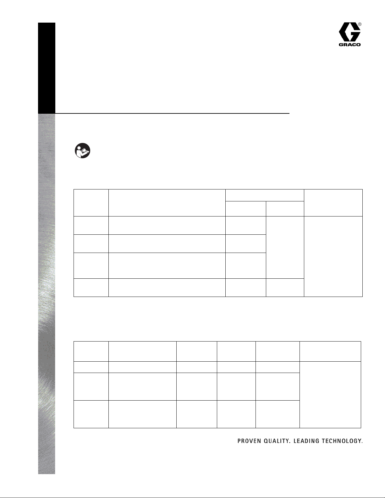
Air Control Assemblies
Provide clean, dry, regulated compressed air
Part No. Description
309923F
Includes Maximum
Regulated Air
PressureRegulator* Filter*
234398 2 regulated outlets and 1 filtered main
line outlet
234399 2 regulated outlets and 2 filtered main
line outlets with gauge and air cock
234400 2 air regulators, each has 2 regulated
outlets and 1 filtered main line outlet
with gauge and air cock
234411 2 regulated outlets and 1 filtered main
line outlet
* Regulator maximum CFM is 50. See table below for maximum filter CFM.
See Air Regulator manual 309924 for additional information on air regulator.
234392 similar to
234392
234392
234392 234410
Air Filters
With 5 micron filtration
Maximum
Part No. Description Inlet Outlets
234396 Air Filter, bare 1/2” npt(f) 3/8” npt(f) 120 CFM
234410 Air Filter, bare 1/2” npt(f) 3/8” npt(f)
1/4” npt(f)
plugged
CFM
75 CFM
234396,
page 6
160 psi
(1.1 MPa, 11 bar)
Maximum Air Inlet
Pressure
175 psi
(1.2 MPa, 12 bar)
234412 Air Filter, quick
coupler
Graco Inc. P.O. Box 1441 Minneapolis, MN 55440-1441 USA
Copyright 2003, Graco Inc. is registered to I.S. EN ISO 9001
1/4” npt(f) 1/4” npt(f)
1/4” npt(f)
plugged
75 CFM
Page 2
Installation
Installation
CAUTION
Do not hang the air control unit directly off a pump air
motor inlet, which could be damaged by the weight of
the unit and operating stress.
Before installing air line components, blow out the pipe
line to remove debris. Be sure air to the regulator is
clean. Erratic operation or loss of regulation is usually
caused by dirt in the regulator.
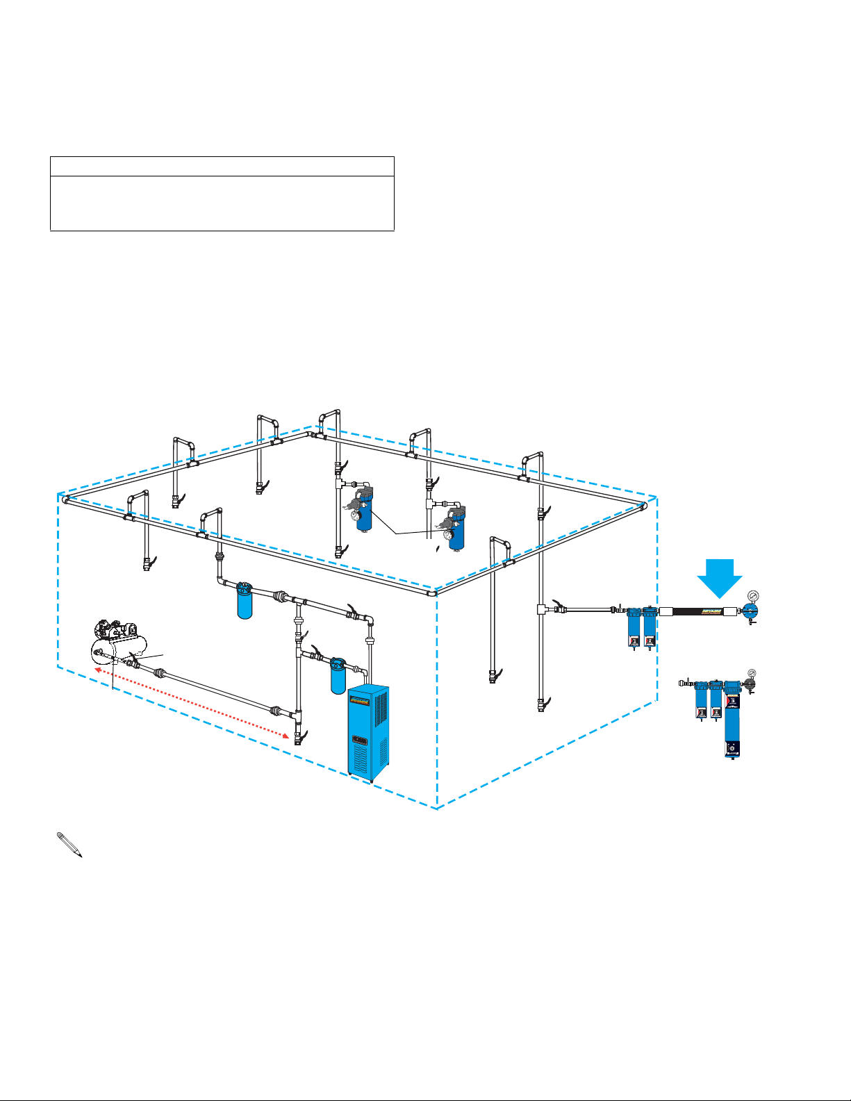
Shop Air Piping Layout
Main Air Line
3/4” (19 mm) minimum
1-1/4” (32 mm) optimum
mm) drops
Use pipe compound or tape sparingly and only on male
threads. Locate the regulator as close as possible to the
equipment it serves.
Install a main air shutoff valve upstream from the air
controls to isolate them for service.
S
l
o
p
e
s
d
o
w
n
a
n
o
m
m
i
n
5
d
a
w
e
n
d
0
’
(
1
a
e
5
y
d
4
”
(
1
1
7
m
.
2
4
m
)
m
)
g
a
l
v
a
n
i
z
e
d
1/2” (13
R
e
c
d
r
o
p
Air Control unit
or Air Filter
Compressor
Ball Valve
Main Air
Coalescer
Air
Filter
Drain
Leg
Shut-off Valve
Flexible hose
between compressor
and stand pipe
1
5
-
2
0
f
t
.
(
4
.
6
-
6
.
1
m
)
Drain Valve
• Main Air Line stand pipe should not be smaller than compressor outlet size.
• A minimum of 25 ft. (7.62 m) from compressor to first filter outlet is required to cool air [50 ft. (15.24 m) optimum]
Membrane air
drying system
Desiccant air
drying system
$%3)##!.4
3!452!
./2-!
4%$
2 309923F
Page 3
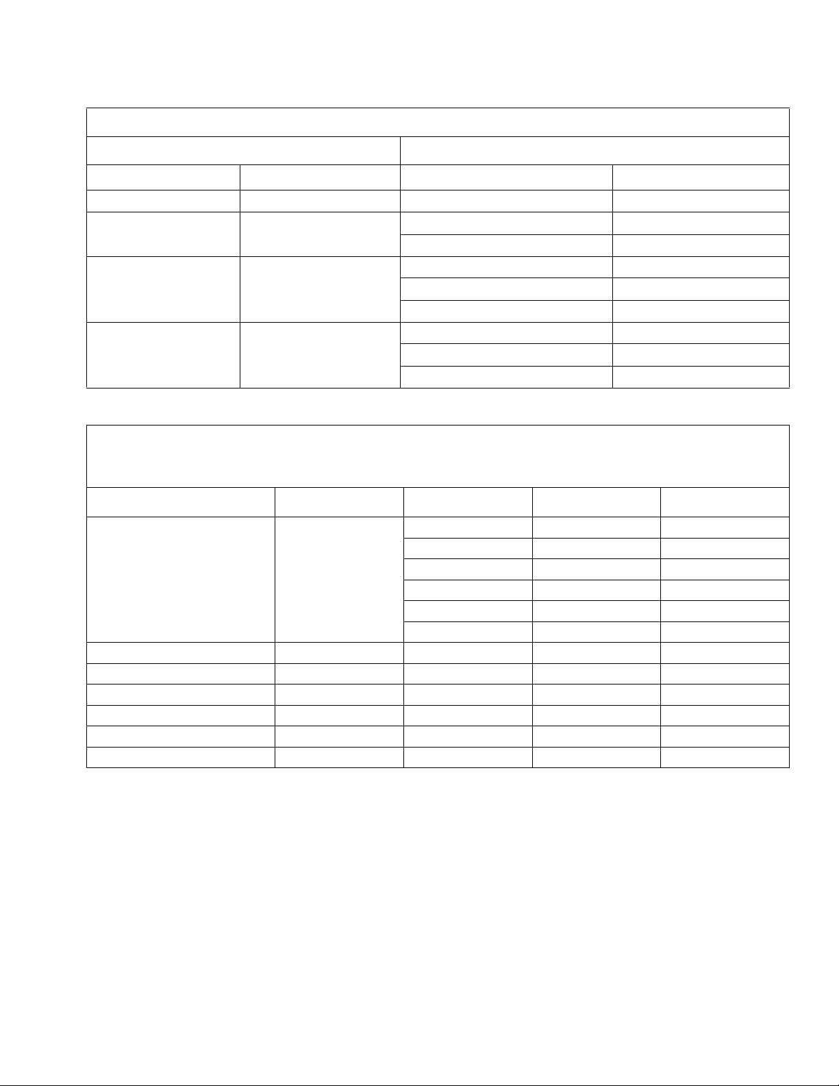
Shop Air Piping Layout
Minimum Pipe Size Recommendations
Compressor Main Air Line
HP CFM Length ft (m) Size in. (mm)
1-1/2 - 2 6 - 9 any 3/4 (19)
3 - 5 12 - 20 Up to 200 (61) 3/4 (19)
Over 200 (61) 1 (25.4)
5 - 10 20 - 40 Up to 100 (30.5) 3/4 (19)
Over100-200 (30.5-61) 1 (25.4)
Over 200 (61) 1-1/4 (31.8)
10 - 15 40 - 60 Up to 100 (30.5) 3/4 (19)
Over100-200 (30.5-61) 1-1/4 (31.8)
Over 200 (61) 1-1/2 (38.1)
Air Pressure Drop Through Hose, by hose length and ID
psi
(Kpa, bar)
Hose ID (in.)
1/4 404 614
Inlet P Hose Length (ft) Pressure Drop SCFM (ft
10810
15 9.5 9
20 11 8
25 12.75 8
50 24
8
3
/min)
309923F 3
Page 4

Operation
Operation
Pressure Adjustment
Do not exceed the Maximum Incoming Air Pressure of
the equipment. Over pressurizing can cause component rupture and serious injury.
Turn clockwise to increase air pressure. Turn
counterclockwise to decrease air pressure.
Maintenance and Repair
Air Filter
Follow the Pressure Relief Procedure before
performing any of the following procedures.
Wash the filter element and bowl with household soap
and water or denatured alcohol. Use compressed air to
blow dirt and contaminants out of the filter body. Blow
out the filter element from the inside.
Clean the air filter regularly to maximize filtering
efficiency and to avoid excessive pressure drop. Fully
relieve pressure before removing the bowl.
Pressure Relief Procedure
To avoid injury, relieve air and fluid pressure before
checking, cleaning, or repairing the equipment.
The following is a basic pressure relief procedure. Be
sure to follow the specific pressure relief procedure in
your spray gun and/or fluid supply equipment manuals.
1. Close the main air shutoff valve.
2. Trigger the gun or dispense valve and open any
drain valves to relieve pressure.
Auto Drain
When the filter bowl is pressurized, the piston travels
down against the spring and closes the drain opening.
When the bowl is depressurized (i.e., overnight when
system is shut down), the spring lifts the piston from the
seal, allowing the bowl to drain.
You can push the piston stem on the bottom of the
bowl to manually drain it.
Air Regulator
See Air Regulator Manual 309924 for maintenance and
repair procedures.
4 309923F
Page 5

Parts
Air Control Assemblies
Parts
Part No. 234398
118489
118488
289149
234392
See manual
309924 for parts
Part No. 234399
289171
289172
289165
See page 6
289341
Part No. 234400
289173
289174
Part No. 234411
289340
Seepage6
289340
289149
118488
289165
234392
See manual
309924 for parts
118489
118488
289149
234392
See manual
309924 for parts
289173
289172
289165
See page 6
289341
289340
289174
118489
118488
289149
234392
See manual
309924 for parts
289341
234410
See page 6
289165
Note: Mounting Bracket
288808 not shown
309923F 5
Page 6

Parts
Air Filters
Parts for Bare Filter 234396 and for
Filter supplied with Air Controls 234398,
234399, and 234400
289175
289171 for
234396, 234398
or
289173 for
234399, 234400
289172
288784
288781
288782
288783
Part No. 234410 and 234412
289175
289178
289179
289149
289180
289181
289182
289183
288785
289176
288786
289177
288743
288743
289176
289184
288786
6 309923F
Page 7

Parts
309923F 7
Page 8

Graco Standard Warranty
Graco warrants all equipment referenced in this document which is manufactured by Graco and bearing its name to be free from defects in
material and workmanship on the date of sale to the original purchaser for use. With the exception of any special, extended, or limited warranty
published by Graco, Graco will, for a period of twelve months from the date of sale, repair or replace any part of the equipment determined by
Graco to be defective. This warranty applies only when the equipment is installed, operated and maintained in accordance with Graco’s written
recommendations.
This warranty does not cover, and Graco shall not be liable for general wear and tear, or any malfunction, damage or wear caused by faulty
installation, misapplication, abrasion, corrosion, inadequate or improper maintenance, negligence, accident, tampering, or substitution of
non-Graco component parts. Nor shall Graco be liable for malfunction, damage or wear caused by the incompatibility of Graco equipment with
structures, accessories, equipment or materials not supplied by Graco, or the improper design, manufacture, installation, operation or
maintenance of structures, accessories, equipment or materials not supplied by Graco.
This warranty is conditioned upon the prepaid return of the equipment claimed to be defective to an authorized Graco distributor for verification of
the claimed defect. If the claimed defect is verified, Graco will repair or replace free of charge any defective parts. The equipment will be returned
to the original purchaser transportation prepaid. If inspection of the equipment does not disclose any defect in material or workmanship, repairs will
be made at a reasonable charge, which charges may include the costs of parts, labor, and transportation.
THIS WARRANTY IS EXCLUSIVE, AND IS IN LIEU OF ANY OTHER WARRANTIES, EXPRESS OR IMPLIED, INCLUDING BUT NOT LIMITED
TO WARRANTY OF MERCHANTABILITY OR WARRANTY OF FITNESS FOR A PARTICULAR PURPOSE.
Graco’s sole obligation and buyer’s sole remedy for any breach of warranty shall be as set forth above. The buyer agrees that no other remedy
(including, but not limited to, incidental or consequential damages for lost profits, lost sales, injury to person or property, or any other incidental or
consequential loss) shall be available. Any action for breach of warranty must be brought within two (2) years of the date of sale.
GRACO MAKES NO WARRANTY, AND DISCLAIMS ALL IMPLIED WARRANTIES OF MERCHANTABILITY AND FITNESS FOR A
PARTICULAR PURPOSE, IN CONNECTION WITH ACCESSORIES, EQUIPMENT, MATERIALS OR COMPONENTS SOLD BUT NOT
MANUFACTURED BY GRACO. These items sold, but not manufactured by Graco (such as electric motors, switches, hose, etc.), are subject to
the warranty, if any, of their manufacturer. Graco will provide purchaser with reasonable assistance in making any claim for breach of these
warranties.
In no event will Graco be liable for indirect, incidental, special or consequential damages resulting from Graco supplying equipment hereunder, or
the furnishing, performance, or use of any products or other goods sold hereto, whether due to a breach of contract, breach of warranty, the
negligence of Graco, or otherwise.
FOR GRACO CANADA CUSTOMERS
The Parties acknowledge that they have required that the present document, as well as all documents, notices and legal proceedings entered into,
given or instituted pursuant hereto or relating directly or indirectly hereto, be drawn up in English. Les parties reconnaissent avoir convenu que la
rédaction du présente document sera en Anglais, ainsi que tous documents, avis et procédures judiciaires exécutés, donnés ou intentés, à la suite
de ou en rapport, directement ou indirectement, avec les procédures concernées.
Graco Information
TO PLACE AN ORDER, contact your Graco distributor or call to identify the nearest distributor.
Phone: 612-623-6921 or Toll Free: 1-800-328-0211 Fax: 612-378-3505
All written and visual data contained in this document reflects the latest product information available at the time of publication.
Graco reserves the right to make changes at any time without notice.
This manual contains English. MM 309923
Graco Headquarters: Minneapolis
International Offices: Belgium, China, Japan, Korea
GRACO INC. P.O. BOX 1441 MINNEAPOLIS, MN 55440-1441
www.graco.com
6/2003 Revised 8/2007
 Loading...