

Page 1
Repair - Parts
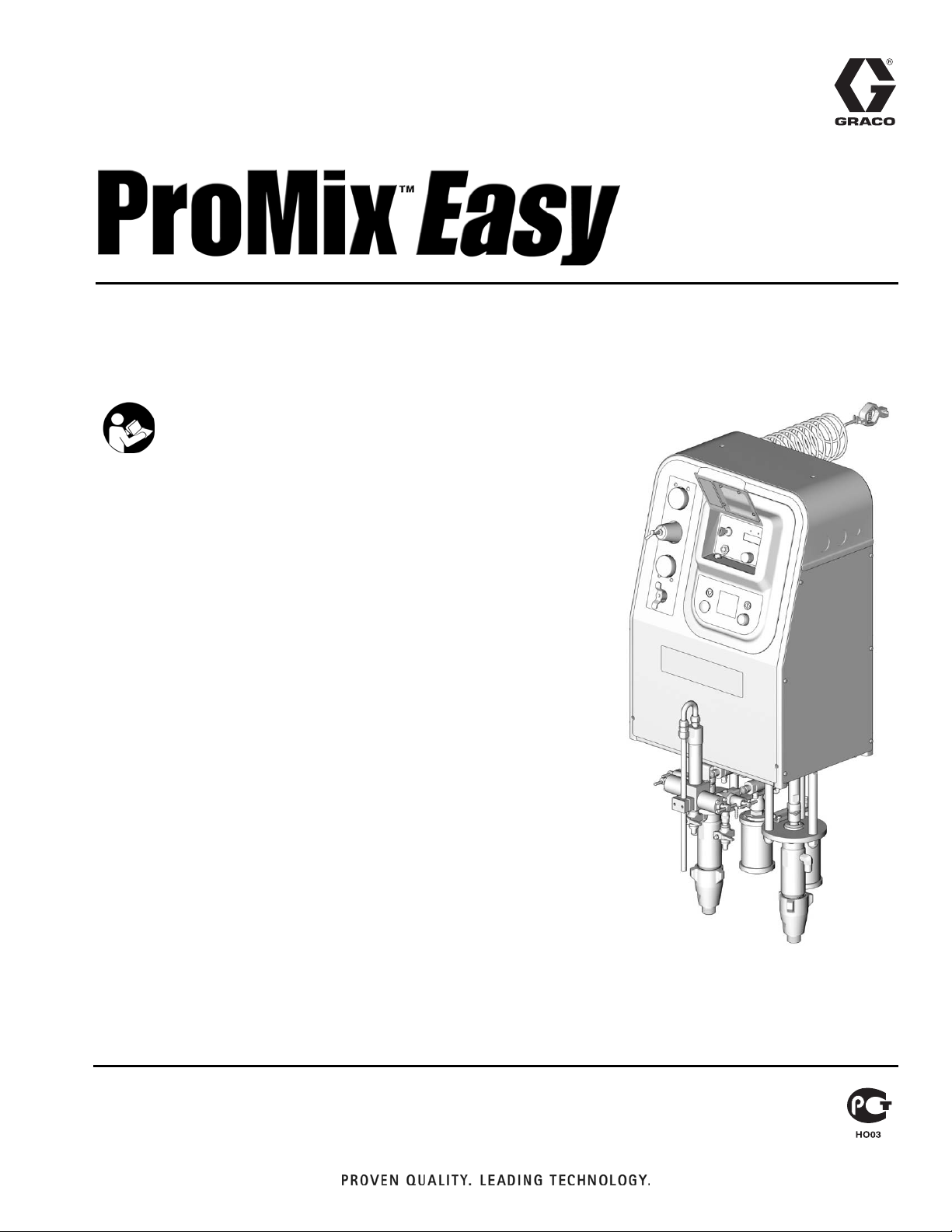
Self-contained, single color, electronic plural component paint proportioner.
For professional use only.
Important Safety Instructions
Read all warnings and instructions in this manual.
Save these instructions.
See page 3 for model information, including maximum working pressure and approvals.
309909H
ENG
TI4909a
Page 2

Manual Conventions
Contents
Manual Conventions . . . . . . . . . . . . . . . . . . . . . . . . 2
ProMix Easy Models . . . . . . . . . . . . . . . . . . . . . . . . 3
Related Manuals . . . . . . . . . . . . . . . . . . . . . . . . . . . 4
Warnings . . . . . . . . . . . . . . . . . . . . . . . . . . . . . . . . . 5
Pressure Relief Procedure . . . . . . . . . . . . . . . . . . . 7
Fluid Manifold to Gun . . . . . . . . . . . . . . . . . . . . . 7
Pump to Fluid Manifold . . . . . . . . . . . . . . . . . . . . 8
Maintenance . . . . . . . . . . . . . . . . . . . . . . . . . . . . . . . 9
Preventive Maintenance Schedule . . . . . . . . . . . 9
Mix Manifold . . . . . . . . . . . . . . . . . . . . . . . . . . . . 9
Dispense Valve . . . . . . . . . . . . . . . . . . . . . . . . . . 9
Pump . . . . . . . . . . . . . . . . . . . . . . . . . . . . . . . . . . 9
Turbine Alternator . . . . . . . . . . . . . . . . . . . . . . . . 9
Air Filters . . . . . . . . . . . . . . . . . . . . . . . . . . . . . . . 9
Pump Test/Meter Calibration . . . . . . . . . . . . . . . . 9
Wet Cup . . . . . . . . . . . . . . . . . . . . . . . . . . . . . . . 9
Storage . . . . . . . . . . . . . . . . . . . . . . . . . . . . . . . . 9
Icing . . . . . . . . . . . . . . . . . . . . . . . . . . . . . . . . . . 9
Troubleshooting . . . . . . . . . . . . . . . . . . . . . . . . . . . 10
Alarms . . . . . . . . . . . . . . . . . . . . . . . . . . . . . . . . . . 13
Repair . . . . . . . . . . . . . . . . . . . . . . . . . . . . . . . . . . . 15
Replacing Air Filter Element . . . . . . . . . . . . . . . 15
User Interface . . . . . . . . . . . . . . . . . . . . . . . . . . 16
Pneumatic Control . . . . . . . . . . . . . . . . . . . . . . 19
Dispense Valve/Mix Manifold Assembly . . . . . . 21
Pump Assembly . . . . . . . . . . . . . . . . . . . . . . . . 21
Electrical Schematic . . . . . . . . . . . . . . . . . . . . . . . 22
248349 Main Control Board Schematic . . . . . . . . 23
246899 Pump Solenoid Expansion Board
Schematic . . . . . . . . . . . . . . . . . . . . . . . . . . . . . 23
Parts . . . . . . . . . . . . . . . . . . . . . . . . . . . . . . . . . . . . 24
Part No. 234596 Series A, Pump-based,
Cart-mounted Air Spray Unit . . . . . . . . . . . . 24
Pump and Meter-based, Wall-mounted
Air Spray Units . . . . . . . . . . . . . . . . . . . . . . 27
Pump-based, Wall-mounted Air Spray Units . . . 30
Meter-based, Wall-mounted High Pressure
Units . . . . . . . . . . . . . . . . . . . . . . . . . . . . . . 33
Pump-based, Wall-mounted High Pressure
Units . . . . . . . . . . . . . . . . . . . . . . . . . . . . . . 36
Pump and Meter-based, Wall-mounted High
Pressure Units . . . . . . . . . . . . . . . . . . . . . . 40
Tube Connections, Low Pressure Pumps . . . . . 44
Tube Connections, High Pressure Pumps . . . . . 45
Tube Connections, Meters . . . . . . . . . . . . . . . . . 46
Pneumatic Schematic . . . . . . . . . . . . . . . . . . . . 47
248270 Intrinsically Safe Pneumatic Control . . . 48
248316 Non-intrinsically Safe
Pneumatic Control . . . . . . . . . . . . . . . . . . . 50
User Interface . . . . . . . . . . . . . . . . . . . . . . . . . . 52
287230 Pump Air Control . . . . . . . . . . . . . . . . . 53
287231 Meter Air Control . . . . . . . . . . . . . . . . . 53
Technical Data . . . . . . . . . . . . . . . . . . . . . . . . . . . . 54
Graco Standard Warranty . . . . . . . . . . . . . . . . . . . 56
Graco Information . . . . . . . . . . . . . . . . . . . . . . . . . 56
Manual Conventions
WARNING
CAUTION indicates a potentially hazardous situation
which, if not avoided, may result in property damage or
WARNING indicates a potentially hazardous situation
which, if not avoided, could result in death or serious
injury.
Warnings included in instructions generally have a
symbol indicating the hazard. Follow the instructions
and read the hazard section on warning pages 5 to 6
for additional information.
2 309909H
destruction of equipment.
Note
A note indicates additional helpful information.
CAUTION
Page 3
ProMix Easy Models
WARNING
Do not install equipment approved only for non-hazardous location in a hazardous area. Substitution of
components may impair intrinsic safety and cause personal injury. Read page 5.
Approved for Hazardous Location
Class I, Div 1, Group D (North America); Class I, Zones 1 and 2 (Europe)
ProMix Easy Models
ProMix
Easy
Part No. Series Description
234596 A
234597 A
234598 A
234599 A
234601 A
234602 A
234603 A
234604 A
234605 A
234606 A
234608 A
234609 A
234611 A
234612 A
234613 A
234618 A
234619 A
Cart mount, UltraMix
Wall mount, UltraMix cst* Pump/G3000 Meter
Wall mount, UltraMix sst** Pump/G3000 Meter
Wall mount, UltraMix cst* Pumps
Wall mount, UltraMix sst** Pumps
Wall mount, HydraMix
Wall mount, HydraMix 500 sst** Pump/G3000 Meter
Wall mount, HydraMix 600 cst* Pump/G3000 Meter
Wall mount, HydraMix 600 sst** Pump/G3000 Meter
Wall mount, HydraMix 500 cst* Pumps
Wall mount, HydraMix 500 sst** Pumps
Wall mount, HydraMix 600 cst* Pumps
Wall mount, HydraMix 600 sst** Pumps
Wall mount, HydraMix 700 cst* Pumps
Wall mount, HydraMix 700 sst** Pumps
Wall mount, G3000 Meter, cst* mix manifold
Wall mount, G3000 Meter, sst** mix manifold
™
cst* Pumps, hose and gun
™
500 cst* Pump/G3000 Meter
Approved for Non-hazardous Location
234600 A
234825 A
234607 A
234826 A
234610 A
234827 A
Wall mount, UltraMix cst* Pumps
Wall mount, UltraMix sst** Pumps
Wall mount, HydraMix 500 cst* Pumps
Wall mount, HydraMix 500 sst** Pumps
Wall mount, HydraMix 600 cst* Pumps
Wall mount, HydraMix 600 sst** Pumps
Maximum Working
Pressure
psi (MPa, bar) Approvals
250 (1.7, 17)
250 (1.7, 17)
250 (1.7, 17)
250 (1.7, 17)
250 (1.7, 17)
Conforms to
FM std 3600 & 3610
for use in
Class I Div 1
Group D T3
Hazardous Locations
2400 (16, 166)
2400 (16, 166)
3400 (23, 234)
3400 (23, 234)
ISSeP 04 ATEX 020X
EEx ia p IIA T3
2400 (16, 166)
2400 (16, 166)
3400 (23, 234)
3400 (23, 234)
4700 (32, 324)
4700 (32, 324)
4000 (28, 280)
CAN/CSA
22.2 No. 157-92
& No. 1010.1-92
4000 (28, 280)
250 (1.7, 17)
250 (1.7, 17)
2400 (16, 166)
2400 (16, 166)
3400 (23, 234)
3400 (23, 234)
9902471
Conforms to
UL61010A-1
Certified to
CAN/CSA
22.2 No. 1010.1-92
0359
* cst=carbon steel. ** sst=stainless steel.
309909H 3
Page 4

Related Manuals
Related Manuals
Component Manuals in English This manual available in the following languages:
Manual Description
309908 ProMix Easy Operation
309909 ProMix Easy Repair-Parts
310654 Fluid Mix Manifold
310655 Dispense Valve
310662 UltraMix and HydraMix Displacement
Pumps
310671 UltraMix Pumps
310672 HydraMix Pumps
310673 Circulation Kits
310674 Stand and Caster Kits
310675 AC Power Supply
310676 Remote Manifold Kit
310677 Heater Installation Kit
310678 TSL Pump Kits
309192 ISO Supply Kit
309623 Data Download Kits
Manual Language
309909 English
310680 French
310682 Spanish
310684 German
310686 Italian
310688 Chinese
310690 Japanese
310769 Dutch
310771 Finnish
310773 Swedish
308778 G3000 Flowmeter
308034 Turbine Alternator Repair Kit
4 309909H
Page 5
Warnings
Warnings
The following general warnings are related to the safe setup, use, grounding, maintenance, and repair of this equipment. Additional more specific warnings may be found throughout the text of this manual where applicable.
WARNING
FIRE AND EXPLOSION HAZARD
Flammable fumes, such as solvent and paint fumes, in work area can ignite or explode. To help prevent
fire and explosion:
• Use equipment only in well ventilated area.
• Eliminate all ignition sources; such as pilot lights, cigarettes, portable electric lamps, and plastic
drop cloths (potential static arc).
• Keep work area free of debris, including solvent, rags and gasoline.
• Do not plug or unplug power cords or turn lights on or off when flammable fumes are present.
• Ground equipment and conductive objects in work area. See Setup instructions in ProMix Easy
Operation manual 309908.
• Use only grounded hoses.
• Hold gun firmly to side of grounded pail when triggering into pail.
• If there is static sparking or you feel a shock, stop operation immediately. Do not use equipment
until you identify and correct the problem.
• Keep a fire extinguisher in the work area.
SKIN INJECTION HAZARD
High-pressure fluid from gun, hose leaks, or ruptured components will pierce skin. This may look like
just a cut, but it is a serious injury that can result in amputation. Get immediate surgical treatment.
• Do not point gun at anyone or at any part of the body.
• Do not put your hand over the spray tip.
• Do not stop or deflect leaks with your hand, body, glove, or rag.
• Do not spray without tip guard and trigger guard installed.
• Engage trigger lock when not spraying.
• Follow Pressure Relief Procedure in this manual, when you stop spraying and before cleaning,
checking, or servicing equipment.
MOVING PARTS HAZARD
Moving parts can pinch or amputate fingers and other body parts.
• Keep clear of moving parts.
• Do not operate equipment with protective guards or covers removed.
• Pressurized equipment can start without warning. Before checking, moving, or servicing equipment, follow the Pressure Relief Procedure in this manual. Disconnect power or air supply.
309909H 5
Page 6
Warnings
WARNING
EQUIPMENT MISUSE HAZARD
Misuse can cause death or serious injury.
• Do not exceed the maximum working pressure or temperature rating of the lowest rated system
component. See Technical Data in all equipment manuals.
• Use fluids and solvents that are compatible with equipment wetted parts. See Technical Data in all
equipment manuals. Read fluid and solvent manufacturer’s warnings.
• Check equipment daily. Repair or replace worn or damaged parts immediately.
• Do not alter or modify equipment.
• For professional use only.
• Use equipment only for its intended purpose. Call your Graco distributor for information.
• Route hoses and cables away from traffic areas, sharp edges, moving parts, and hot surfaces.
• Do not kind or overbend hoses or use hoses to pull equipment.
• Comply with all applicable safety regulations.
TOXIC FLUID OR FUMES HAZARD
Toxic fluids or fumes can cause serious injury or death if splashed in the eyes or on skin, inhaled, or
swallowed.
• Read MSDS’s to know the specific hazards of the fluids you are using.
• Store hazardous fluid in approved containers, and dispose of it according to applicable guidelines.
PERSONAL PROTECTIVE EQUIPMENT
You must wear appropriate protective equipment when operating, servicing, or when in the operating
area of the equipment to help protect you from serious injury, including eye injury, inhalation of toxic
fumes, burns, and hearing loss. This equipment includes but is not limited to:
• Protective eyewear
• Clothing and respirator as recommended by the fluid and solvent manufacturer
•Gloves
• Hearing protection
6 309909H
Page 7
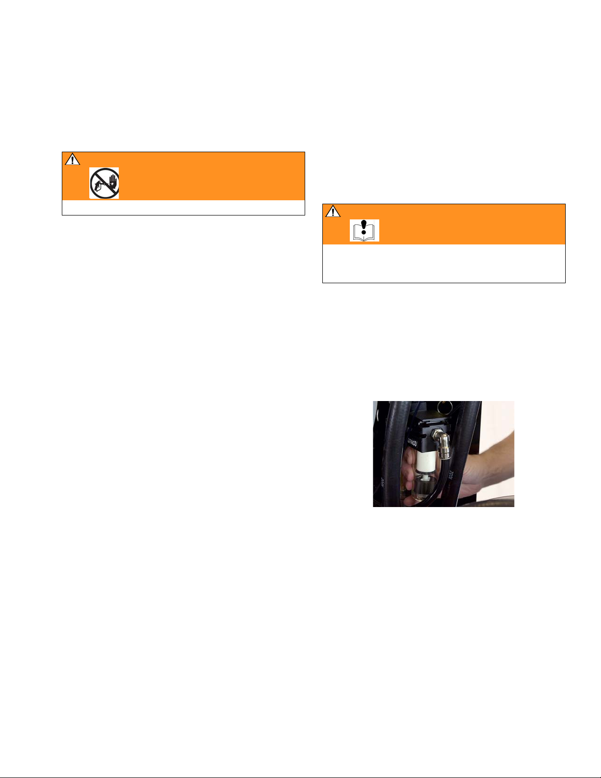
Pressure Relief Procedure
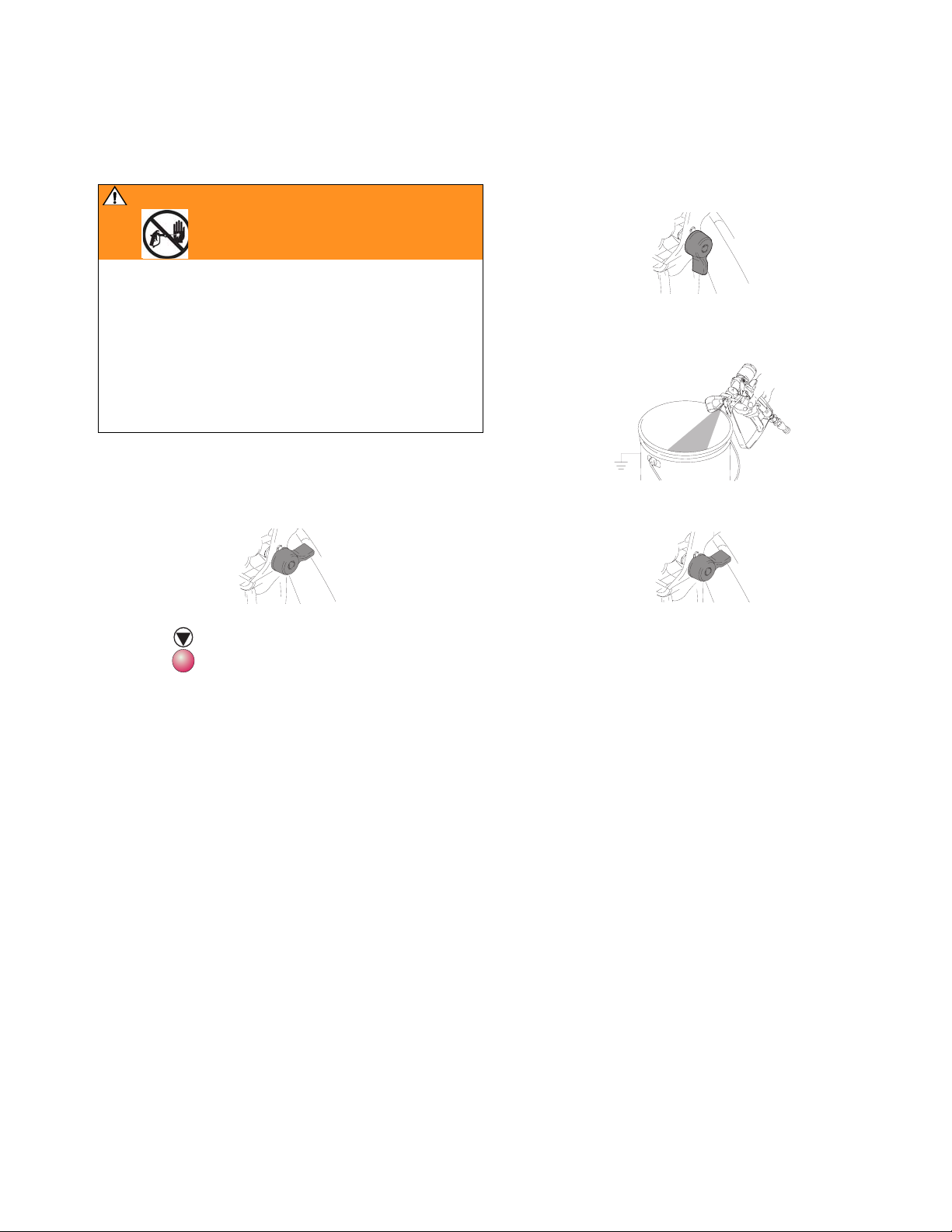
Pressure Relief Procedure
WARNING
Relieve pressure from fluid manifold to gun whenever
you stop spraying and before servicing gun or removing spray tip.
In addition, relieve pressure from pump to fluid manifold at end of day and before cleaning, checking, or
servicing pump, manifold, or fluid line accessories or
transporting equipment.
Read warnings, page 5.
Fluid Manifold to Gun
1. Engage trigger lock.
3. Disengage trigger lock.
4. Hold a metal part of the gun firmly to a grounded
metal pail. Trigger gun to relieve pressure.
5. Engage trigger lock.
2. Press .
309909H 7
Page 8
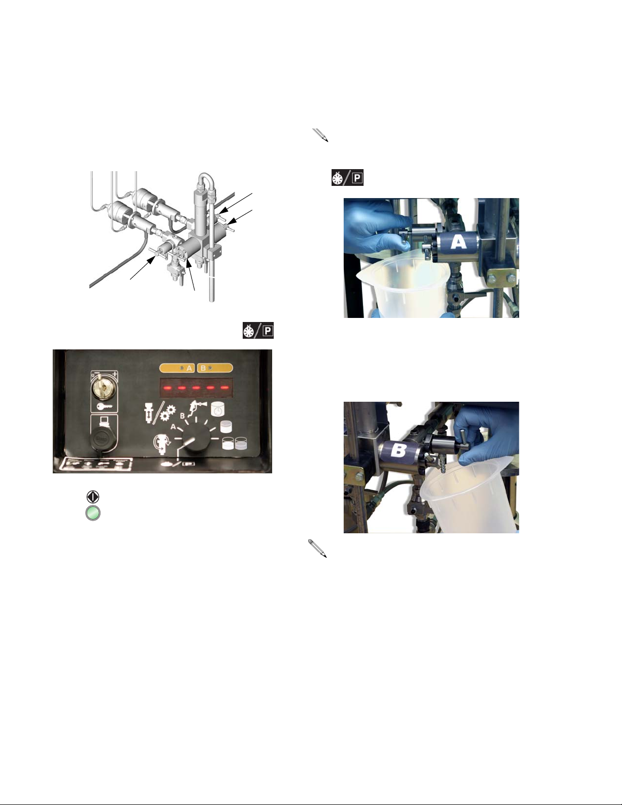
Pressure Relief Procedure
Pump to Fluid Manifold
1. Close shutoff valves G
2. Place waste container under sampling valves H
B
and H
.
A
H
3. Turn function knob to pressure relief/park .
A
and GB.
A
B
H
B
G
A
G
TI4699a
5. Open sampling valve A slowly to bleed off pressure.
Indicator A will stay on for 5 sec after Pump A
reaches Park position, then go off.
Pump air supply pressure must be sufficient to
cause pumps to stroke to bottom-most position
when function knob to is set to pressure relief/park
.
6. Indicator B comes on and Pump B pressurizes.
7. Open sampling valve B slowly to bleed off pressure.
Indicator B will stay on for 5 sec after Pump B
reaches Park position, then go off.
4. Press . Indicator A comes on, and Pump A pres-
surizes.
If both pumps are not parked after 1 min, Alarm
26 will sound.
8. Close sampling valves A and B before restarting
system.
8 309909H
Page 9
Maintenance
Maintenance
Preventive Maintenance Schedule
Establish a preventive maintenance schedule, based on
the pump’s repair history.
Mix Manifold
See mix manifold manual 310654.
Dispense Valve
See dispense valve manual 310655.
Pump
See applicable pump manual 310671, 310672, or
310662.
Turbine Alternator
Replace bearings every 2000 hours. See page 19.
Air Filters
Check daily. Drain and clean as necessary. See page
15.
Pump Test/Meter Calibration
See ProMix Easy Operation manual. If pumps/meters
fail test, see Troubleshooting, page 10.
Wet Cup
Check pump and dispense valve wet-cups daily. Keep
filled with Graco Throat Seal Liquid (TSL), Part No.
206995.
Storage
Before storing the pump, always flush it, see ProMix
Easy Operation manual. Relieve the pressure, page 7.
Icing
If you experience icing at the pump air manifold:
• Reduce pump input air pressure below 80 psi (0.56
MPa, 5.6 bar), if required spray pressure allows.
• Reduce moisture in compressed air supply, or use
heated air.
If icing persists, see table below.
Problem Solution
Pump slows on both up
and down stroke.
Pump slows on down
stroke.
Pump slows on up stroke. Turn U port bleed screw 90° (1/4 turn) counter-
309909H 9
Turn D port bleed screw 60° (1/6 turn) counterclockwise, to bleed 1 cfm air to melt ice.
Turn D port bleed screw 60° (1/6 turn) counterclockwise, to bleed 1 cfm air to melt ice. If icing
continues, turn screw to 90° (1/4 turn) to increase
air flow to 2 cfm. If necessary, increase air flow to
3 cfm by turning screw to 270° (3/4 turn). Do not
exceed 3 cfm (3/4 turn maximum).
clockwise, to bleed 1 cfm air to melt ice. If icing
continues, turn screw to 120° (1/3 turn) to
increase air flow to 2 cfm. If necessary, increase
air flow to 3 cfm by turning screw to 180° (1/2
turn). Do not exceed 3 cfm (1/2 turn maximum).
U
D
TI5294a
Page 10
Troubleshooting
Troubleshooting
WARNING
If an alarm code displays, see page 13.
Read warnings, page 5-6.
Problem Cause Solution
Display not lit.
No electric power.
Pumps do not run. Air pressure to pumps too low. Increase pressure to 50 psi (0.35 MPa,
Pump test volume is not correct. Air pressure to pumps too low Increase pressure to 50 psi (0.35 MPa,
Air valve not turned on. Turn on main air valve to system.
Air supply pressure too low. Increase pressure to 60 psi (0.42 MPa,
4.2 bar) or greater.
Air supply filters plugged. Clean filter bowls; replace filter elements.
Page 15.
Turbine air regulator set too low. Adjust to proper setting.
Turbine alternator failure. Repair or replace turbine. Page 19.
Power supply not connected to main
board.
Main board not connected to display
board.
Display board failure. Replace display board. Page 18.
Power not connected to unit (non-IS units
only).
Solenoid valve stuck. Actuate solenoid manually, if it does not
Dispense valve(s) not opening. Service or replace valve(s). See 310655.
Sensors not functioning properly. Check position of sensors. See ProMix
Pump cavitating excessively. Check for air in lines caused by loose fit-
Check power connections to main board.
See Electrical Schematic, page 22.
Check electrical connections between
display and main board. See Electrical
Schematic, page 22, and 248349 Main
Control Board Schematic, page 23.
Ensure that power cord is plugged in.
Check that cord is connected properly;
see ProMix Easy Operation manual.
3.5 bar).
operate, replace solenoid. Page 20.
3.5 bar).
Easy Operation manual, and applicable
pump manual.
Check board calibration and recalibrate if
necessary. See ProMix Easy Operation
manual.
Replace sensors. See pump manual
310671 or 310672.
ting or use of agitator.
Material too viscous. Use heater.
10 309909H
Page 11

Troubleshooting
Problem Cause Solution
Paint does not cure consistently. Ratio not set correctly. Check that correct ratio is set and set by
volume. See ProMix Easy Operation
manual.
Material not mixing correctly. Test pump. Page 9.
Make sure mixer is clean; flush as
needed. See ProMix Easy Operation
manual.
Pump not operating correctly. Observe whether pumps are loading and
checking correctly, if not, clean and repair
pump. See displacement pump manual
310662.
Poor spray pattern. Fluid pressure too low. Increase pump pressure.
Spray tip dirty or worn. Relieve pressure. Clean or replace tip.
Follow gun manual instructions.
Fluid A or B filters plugged. Clean filters.
Mixer or hoses partially plugged or too
restrictive.
System runs erratically. Air filter(s) clogged. Replace elements. Clean. Replace element(s). See page 15.
Air supply hoses undersized. Replace hoses with appropriate size.
Air compressor undersized. Use larger air compressor.
Air supply pressure tank undersized. Use larger pressure tank.
Air supply relief valve opens. Turbine air regulator set too high. Lower setting to 23-25 psi (172-241 kPa,
Turbine alternator makes high-pitched
whining noise.
Display shows 88888 or unit reboots
unexpectedly.
ProMix Easy does not start when start
button is pressed.
Dispense valves leaking. Loose or worn packings. Tighten packing nut. If leak continues,
Turbine bearings worn. (Setting turbine
air regulator too high, wears bearings.)
Turbine is not supplying enough power to
board.
Faulty start switch or wire harness. Check start switch and wiring harness
Faulty stop switch or wiring harness. Check stop switch and wiring harness
Bad I/O port on display board. Replace board. Page 18.
Bad I/O port on main board. Replace board. Page 17.
Inspect parts for cured material. Clean or
replace, or use larger hoses and mixer.
1.7-2.4 bar).
Replace bearings. Page 19.
Increase turbine regulator setting to
23-25 psi (172-241 kPa, 1.7-2.4 bar).
Check turbine and electrical control
exhaust air for restrictions.
Replace turbine bearings. Page 19.
continuity; switch is normally open circuit.
See Electrical Schematic, page 22.
continuity; stop switch is normally closed
circuit. See Electrical Schematic, page
22.
replace packings. See 310655.
309909H 11
Page 12
Troubleshooting
Problem Cause Solution
Flow rate too low. Inadequate air supply. Use larger CFM compressor.
Air pressure to pumps too low. Increase pressure.
Fluid A or B filters plugged. Clean filters.
Spray tip too small. Relieve pressure. Install larger tip. Follow
gun manual instructions.
Mixer or hoses partially plugged or too
restrictive.
Insufficient dispense valve travel. Increase travel. See 310655.
Shutoff valves are not fully open. Ensure that shutoff valves are fully open
Inspect parts for cured material. Clean or
replace, or use larger hoses and mixer.
and sampling valves are closed.
Pump stops after 12 cycles.
Pump cycle rate slows and eventually
stops.
Knob is set to Run pump A
or B
Turn knob to spray
rial.
independently.
Icing at pump air manifold. See Icing, page 9.
if spraying mate-
12 309909H
Page 13

Alarms
* Indicates error where audible alarm sounds once briefly. ** Indicates error where audible alarm sound pulses.
Code Alarm Active Problem Cause
Startup Errors
01 Sensor Error A* Always No signal from pump A
sensor
02 Sensor Error B* Always No signal from pump B
sensor
03 Communication Error* Always Loss of communication
between main and display boards
Operating Errors
04 not used
05 not used
06 Pump Error A** Spray
07 Pump Error B**
08 Sensor Code Error Always Sensor values reverted to
09 Metering Error A** Spray A dose too great Dispense valve A leak
Te st
Batch
Pump does not stall after
top change over
Pump cavitating excessively
default
Loose cable, failed sensor or cable, failed magnet
assembly
Loose cable, failed sensor or cable, failed magnet
assembly
Loose cable, failed board
Intake valve leak
Air in lines caused by loose fitting or use of agitator
Empty fluid supply
Sensor value data corrupt; board needs replacement
and /or recalibration
Empty B fluid supply
Alarms
Clogged flow meter
10 Metering Error B** Spray B dose too great Dispense valve B leak
Empty A fluid supply
Clogged flow meter
11 Sensor Reading Low A* Spray
12 Sensor Reading Low B*
13 Sensor Reading High A* Spray
14 Sensor Reading High B*
21 Pot Life Error Spray
Te st
Batch
Te st
Batch
first, then
Always
Pump stroke travels
beyond sensor range at
top change over
Pump stroke travels
beyond sensor range at
bottom change over
Pot life timer timed out Not enough material sprayed after last reset
Sensor or bracket loose
Sensor magnet dirty
Sensor or bracket loose
Sensor magnet dirty
309909H 13
Page 14

Alarms
Code Alarm Active Problem Cause
Operating Errors
(continued)
22 High Ratio (units with
meter[s] only)
23 Low Ratio (units with
meter[s] only)
24 Dose Timeout A (units
with meter[s] only)
25 Dose Timeout B (units
with meter[s] only)
26 Park Timeout
(pump-based units only)
Testing Error
15 Piston packing/ball A* Test Pump does not com16 Piston packing/ball B*
17 Inlet Ball A* Test Pump does not com18 Inlet Ball B*
19 Dispense Valve A* Test Pump does not com20 Dispense Valve B*
27 Pump Calibration
Timeout A
28 Pump Calibration
Timeout B
Spray Mix ratio higher than
Tar g et + Tole r anc e
Spray Mix ratio lower than
Target - Tolerance
Spray Air flow switch indicates
more than 40 sec of air
flow without dose completing
Park Pumps not at bottom of
stroke
pletely stall in up stroke
pletely stall in downstroke
pletely stall in both up
and down strokes
Run A Pump doesn’t run
through calibration.
Run B
Flow rate too high
Slow actuation of dispense valve A or B
Clogged flow meter
Air flow switch stuck open.
Atomizing air leak downstream of air flow switch.
Clogged flow meter.
Gun triggered without fluid (dusting parts)
Sampling valves closed, or gun not triggered.
Piston packing or ball check failure
Intake valve ball check failure
Throat packing or dispense valve failure
Sampling valves closed.
14 309909H
Page 15
Repair
Repair
Flush before repairing equipment, if possible. See ProMix Easy Operation manual.
WARNING
Read warnings, page 5.
Follow Pressure Relief Procedure, page 7, if service
time may exceed pot life time, before servicing fluid
components, and before transporting equipment to a
service area.
Replacing Air Filter Element
There are 2 air filters on the unit: the 5 micron air manifold filter (7) and 40 micron pump air filter (9). Check filters daily and replace element as needed. Order
15D909 5 micron filter and 15D890 40 micron filter.
WARNING
Removing the bowl of a pressurized air filter could
cause serious injury. Do not service air filter until air
line is depressurized.
1. Close main air shutoff valve on air supply line and
on unit.
2. Remove left side plate (21).
3. Unlock filter bowl guard and remove.
4. Unscrew filter bowl.
5. Remove and replace element.
6. Screw filter bowl on securely.
7. Reassemble.
309909H 15
Page 16
Repair
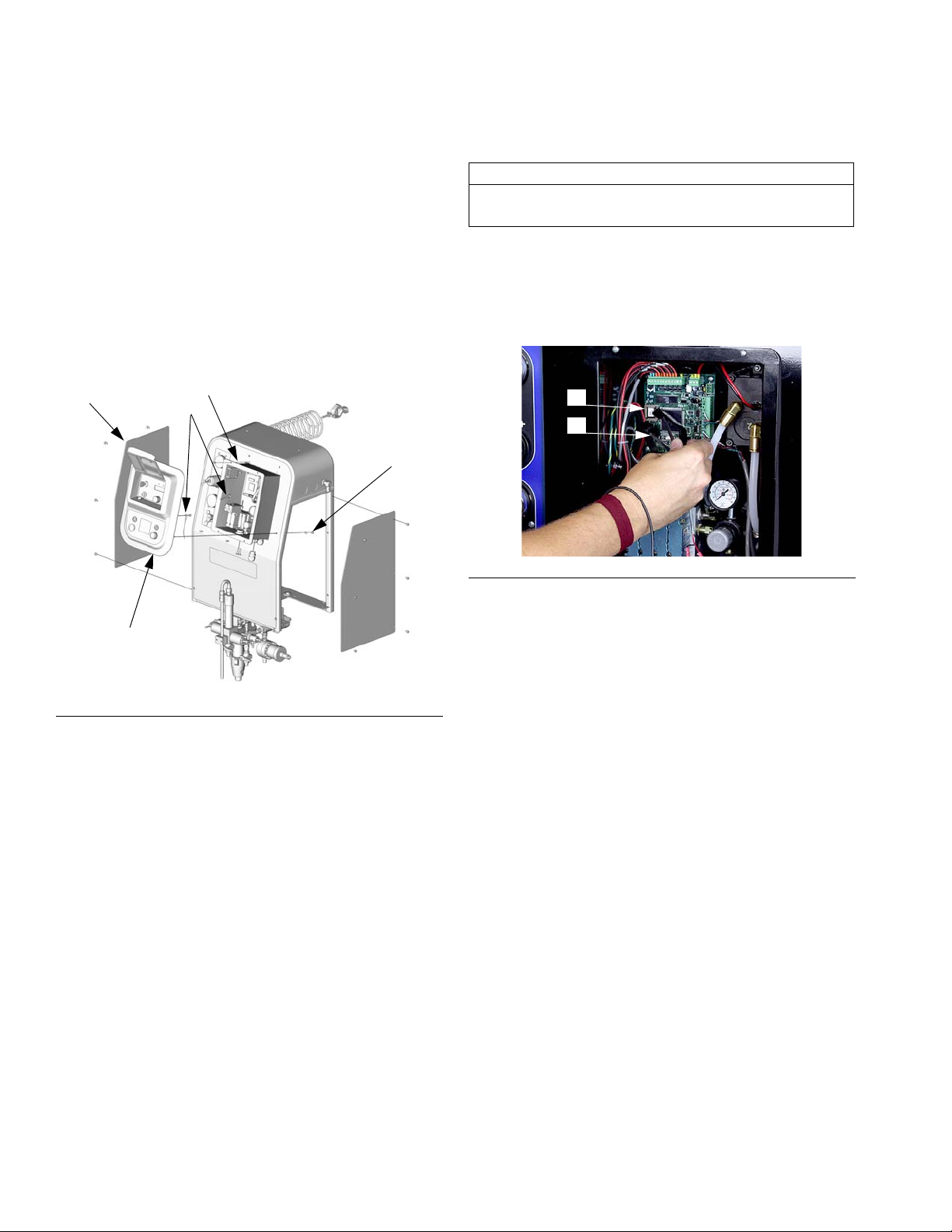
User Interface
Removal
1. Close main air shutoff valve on air supply line and
on unit.
2. Remove side panels (21).
3. Remove fasteners (45). Gently pull user interface
(11) away from pneumatic control (10).
21
10
315
45
Software Upgrades
CAUTION
To avoid damaging circuit board, wear a grounding
strap.
1. Remove User Interface cover. See above.
2. Use a chip remover (D) to remove software chip (C).
F
IG. 2.
C
D
F
IG. 2
11
TI4901a
F
IG. 1
4. To completely remove user interface (11), disconnect ground wire (315), and wires (416 and 406)
from main control board (301). See Electrical
Schematic, page 22.
3. Install new chip (beveled corner down).
4. Reassemble.
5. Recalibrate main circuit board. See ProMix Easy
Operation Manual.
16 309909H
Page 17
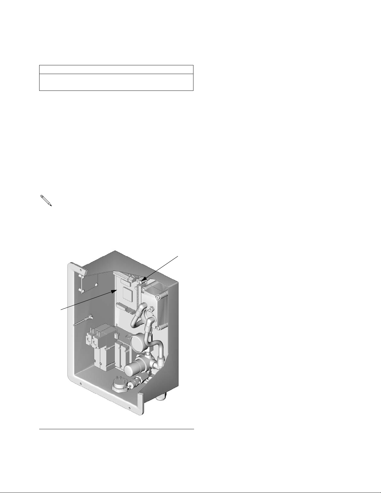
Replacing Main Circuit Board
CAUTION
To avoid damaging circuit board, wear a grounding
strap.
1. Remove User Interface cover. See page 16.
2. Disconnect all wire connectors from board (301).
F
IG. 3.
3. Remove four screws (302) and replace board (301).
4. Reassemble. Refer to Electrical Schematic, page
22.
5. Recalibrate system. See ProMix Easy Operation
Manual.
NOTE: If the main control board is replaced on
units that use a flow meter, the flow meter calibration data must be set using a PC and a Data
Download Kit (Graco P/N 248403 for hazardous
locations or Graco P/N 248404 for non-hazardous
locations).
Repair
F
320
301
TI4561a
IG. 3
309909H 17
Page 18

Repair
Replacing Display Circuit Board
CAUTION
To avoid damaging circuit board, wear a grounding
strap.
1. Remove User Interface cover. See page 16.
2. Disconnect wires from display board (410). F
404
413 418
407
N
3. Remove two screws (411).
4. Loosen setscrew (419) from knob (405) and remove
knob assembly. Remove jam nut (N).
5. Remove and replace display board (410).
6. Reassemble. Refer to Electrical Schematic, page
22.
IG. 4.
410
411
406
405
419
FIG. 4
403
401
TI4755a TI4756a
406
416
407
403
416
18 309909H
Page 19

Repair
Pneumatic Control
Alternator Repair
Turbine Alternator Repair Kit 223688 is available to
replace turbine bearings.
1. Remove User Interface cover. See page 16.
P
306r
301
310
304
• Lightly lubricate turbine o-ring before installing turbine in housing.
• Connect alternator red wire to + side and
black wire to – side of main circuit board.
• Connect turbine to 3-pin connector on main
circuit board.
305
310
F
IG. 6
304
304d
313
TI4561a
F
IG. 5
2. Disconnect power supply wires (P). F
IG. 5.
3. Disconnect two air lines (310) from alternator (304).
F
IG. 6.
4. Remove top nut (305) and loosen bottom nut. Slide
alternator up and off bottom nut.
5. Remove four screws (304d) to separate alternator
housings. F
IG. 7.
6. Disconnect turbine (304e) from board (A). Follow
instructions in turbine kit manual 308034 to remove
and repair turbine.
7. Replace gasket (304a) if damaged. Place between
housings before securing with screws (304d).
1
304d
1
Torque to 20 in-lbs (2 N•m)
IG. 7
F
A
304a
304e
8. Reassemble. Refer to Electrical Schematic, page
22.
309909H 19
Page 20

Repair
Replacing Solenoids
Follow this procedure to replace a single solenoid.
1. Remove User Interface cover. See page 16.
2. Disconnect two solenoid wires (V) from main board.
F
IG. 8.
3. Disconnect dispense valve pilot lines (A1, A2, B1,
B2). F
IG. 8.
4. Remove two screws (S).
5. Remove and replace solenoid (306b).
From left to right, solenoid functions are as follows:
• Component A
• Component B
6. Reassemble. Solenoid wires are polarized (red +,
black –). Refer to Electrical Schematic, page 22.
Replacing Alternator Regulator
1. Remove User Interface cover. See page 16.
3. Disconnect supply and exhaust air lines (310). F
IG.
5, page 19.
4. Disconnect solenoid wires 12 position Phoenix connector (306r) from main board.
5. Remove solenoid module (306) with regulator
(306e). F
IG. 8.
6. Unscrew and replace regulator (306e).
7. Reassemble. Refer to Electrical Schematic, page
22.
Make sure gaskets (306j, 306k) are in place when
reinstalling solenoid module.
8. Set regulator to 24 psi (160 kPa, 1.6 bar).
Replacing Alarm
1. Remove User Interface cover. See page 16.
2. Disconnect alarm wires from main board.
3. Unscrew alarm (313) and replace. F
IG. 5, page 19.
2. Remove two screws (309) from the back of the control box.
Dispense Valve
Pilot Lines
A1 (off), clear tube
1
Set regulator pressure to 24 psi (160 kPa, 16 bar).
2
Safety relief valve (306t) is required on all IS units.
A2 (on), black tube
B1 (off), green tube
B2 (on), red tube
B1
A1
B2
A2
306k
306j
TI4699a
F
IG. 8
4. Reassemble. Refer to Electrical Schematic, page
22.
310
306e
V
AB
306t
B2
A2
A1
S
B1
306b
TI4558a
1
2
20 309909H
Page 21

Repair
Dispense Valve/Mix Manifold Assembly
WARNING
Read warnings, page 5.
See the Parts drawing for your model.
1. Follow Pressure Relief Procedure, page 7.
2. Label all air and fluid lines, and disconnect from fittings on manifold assembly.
3. Remove fasteners.
4. Remove mix manifold (2).
5. To repair mix manifold, see manual 310654. To
repair dispense valves, see manual 310655.
6. Reassemble.
Pump Assembly
WARNING
Read warnings, page 5.
See the Parts drawing for your model.
1. Follow Pressure Relief Procedure, page 7.
2. Remove side plates (21).
3. Remove wire harnesses from sensor and solenoids.
Refer to Electrical Schematic, page 22.
4. Disconnect fluid inlet and outlet lines from pump
lower. Disconnect air supply from pump.
5. Label all tubing and disconnect from fittings on
pump assembly.
6. Remove mounting hardware and slide pump out of
frame.
7. Repair as instructed in pump manuals 310671,
310672, or 310662.
8. Reassemble.
309909H 21
Page 22

Electrical Schematic
Electrical Schematic
AIR INPUT
3
1
2
COM PORT PIN LOCATIONS
FRONT SIDE VIEW
(OPPOSITE SIDE OF SOLDER CUPS)
TX
GND
RX
FRONT PANEL
COM PORT
RS232
CONNECTOR
1
2
4
START
3
3
15A851
START/STOP
SWITCH ASSY
STOP
GND
A
LIGHT
B
KEY SWITCH ASSY
15A852
2
GND
1
2
1
1
2
KEY SWITCH
MOM.
8
1
+-
7
2
27
POWER SUPPLY ASSEMBLY 245223
POWER
POWER
SUPPLY
SUPPLY
BARRIER
WHITE
3
245706
BROWN
GREEN
BLACK
4
53412
12345
RED
BLACK
GREEN
3
152
J3
1
2
3
6
RED
MOTOR B DOWN
MOTOR A DOWN
MOTOR B UP
MOTOR A UP
-
+
+
-
-
+
-
125
P4
246899
+
RED
BLACK
RED
RED
RED
RED
15D794
BLACK
BLACK
BLACK
BLACK
6
3
7
8
4
ALARM COM
ALARM +
WHITE
COMM PORT ASSY
15A850
ALARM ASSY 15A849
6378412
5
G
S
P
BOARD
239790
SOLENOID
BOARD
1
2
J2
DISPLAY BOARD
J1
METER A
243678
OPT. SOLENOID, RECIRC. 552180
FLUID
VALVES
1
5
4
2
6
2
3
431
5
6
4
1
3
"B"
SENSOR
243678
"A"
SENSOR
METER B
526
234628
AIR FLOW SWITCH
11
119159
1
26
1
2
GREEN
WHITE_W/GRN
3
3
ORANGE
WHITE_W/ORANGE
4
5
458117
CABLE # 15D607 (X2)
BLUE
WHITE_W/BLUE
8
9
6
9
6
GREEN
WHITE_W/ORANGE
WHITE_W/GRN
10714
11
12
10
12
ORANGE
RED
BLACK
WHITE
WHITE
SIGNAL A
COM
12VDC
SIGNAL B
123456788
J8
123
4
ORANGE
567
BLUE
WHITE_W/BLUE
BLACK
WHITE
CABLE # 15A854 (MAIN TO DISPLAY)
RED
SHIELD
1
526
3
4
16
17
13
1234567
18
15
J2
1234567
18
15
16
17
13
14
1
J1
12345
6
CABLE # 114213
+
- SOLENOID VALVE A
+
- SOLENOID VALVE B
+
-
SHIELD
1
15VDC
1
RED
BLACK
COM
3
2
12VDC
RED
RED
RED
BLACK
5
6
3
BLACK
RED
ORANGE
RED
BLACK
BLACK
BLACK
BLACK
12VDC
1
10
72811412
12
9
JUMPER (15V)
J4
1
9
10
11712
Under operating conditions, voltage
at J6 will be approximately 12 Vdc.
1
J6
123
J5
1234568
248349
MAIN CONTROL
BOARD
22 309909H
Page 23

248349 Main Control Board Schematic
248349 Main Control Board Schematic
Pin 1 Pin 1
J5
D12 D6 D13 D5 D10
U4
J6
F1
J4
Pin 1
D2
J2
J1
J8
Pin 1 Pin 1 Pin 1
TI11316a
248349 Main Control Board LEDs
LED Description
D2 In normal operation D2 flashes on and off in 1
second intervals. If D2 is off (not flashing),
software is not booting; check for power to
the board or a short circuit.
D5 On: Dispense valve B is on (open).
Off: Dispense valve B is off (closed).
D6 Active only on units with recirculation option.
On: Recirculation solenoid is on.
Off: Recirculation solenoid is off.
D10 On: Dispense valve A is on (open).
Off: Dispense valve A is off (closed).
D12 On: Remote alarm output on.
Off: Remote alarm output off.
D13 D13 is always off. Output powers the 246899
Expansion Board, turning the board on and
off.
246899 Pump Solenoid Expansion Board Schematic
246899 Pump Solenoid Expansion Board LEDs
LED Description
D1 D2 D3 D4
1
P4
Pin 1
Pin 1
J1
P3
P2
P1
TI11229a
D1 On: Pump B is on the downstroke.
D2 On: Pump B is on the upstroke.
D3 On: Pump A is on the downstroke.
D4 On: Pump A is on the upstroke.
S
G
P
309909H 23
Page 24

Parts
Parts
Part No. 234596 Series A, Pump-based, Cart-mounted Air Spray Unit
11
21, 28
22
103
104
102
41
20
38
72
79
39
10
45
51
71
71
21
22
85
22
100
30
73
84
101 (Ref)
24 309909H
101
101 (Ref)
98
81
TI4769a
Page 25

Part No. 234596 Series A, Pump-based, Cart-mounted Air Spray Unit, continued
Parts
12
49
48
63
75
67
65
76
82
74
47
40
47
25
37
9
32
33
16 17
17
16
15
5
15
3
1
65 (Ref)
39
46
15
4
24
7
8
45
31
6
32
33
24 (Ref)
23
Pump Solenoid
Cable Connections
2 1
45
17
16
78
1
Downstroke solenoid is on the outside.
2
Upstroke solenoid is on the inside.
TI11228a
14
44
2
63
78 (Ref)
TI4770a
309909H 25
Page 26

Parts
Part No. 234596 Series A, Pump-based, Cart-mounted Air Spray Unit, continued
Ref.
No. Part No. Description Qty.
1 15D771 FRAME, wall mount
2 234593 MIX MANIFOLD; see 310654
3 287230 CONTROL, air; see page 53
4 109544 ELBOW, pipe; 3/8 npt (mbe)
5 116756 ELBOW, street, 45°; 3/8 npt (m x f)
6 155665 UNION, adapter; 3/8 npsm(f) x
3/8 npt(m)
7 117629 FILTER, air; 5 micron
8 114316 ELBOW; 3/8 npt(m) x
3/8 in. (10 mm) OD tube fitting
9 15D795 FILTER, air; 40 micron
10 248270 PNEUMATIC CONTROL,
intrinsically safe; see page 54
11 234620 USER INTERFACE; see page 52
12 248570 PUMP, UltraMix; see 310671
14 15D873 BRACKET, support, fluid manifold
15 C38211 ELBOW; 1/2 npt(m) x
3/8 in. (10 mm) OD tube
16 C19038 WASHER, lock; 1/4
17 112925 SCREW, cap, button hd;
1/4-20 x 3/8 in. (10 mm)
20 103196 SCREW, machine, phillips;
8-32 x 7/16 in. (11 mm)
21 15D767 PLATE, side
22 119291 SCREW, self-tapping
23 113802 SCREW, hex hd, flanged;
3/8-16 x 5/8 in. (16 mm)
24 220598 HOSE, air; nitrile; 1/2 in. (13 mm)
ID; 1/2 npt (mbe); 18 in. (457 mm);
see also pages 44 and 47
25 C19024 ELBOW, swivel; 1/2 npt(m) x
1/2 npsm(f)
26 15D607 CABLE, sensor; see Electrical
Schematic, page 22
27 15D794 HARNESS, connector; see Electri-
cal Schematic, page 22
28▲ 290331 LABEL, warning
30 15D775 CART
31 101765 GROMMET
32 100451 COUPLING; 1/8 npt (fbe)
33 115671 CONNECTOR; 1/8 npt(m) x
1/4 in. (6 mm) OD tube
37 244524 GROUND WIRE
38 113279 PLUG, tube fitting;
5/32 in. (4 mm) OD tube
39 113505 NUT, keps, hex hd; 10-24
40 551787 SCREW, cap, button hd;
10-32 x 3/8 in. (10 mm)
41 111218 CAP
44 114104 SCREW, machine; 1/4-20 x
1-1/2 in. (38 mm)
45 115942 NUT, hex, flange hd; 1/4-20
20
Ref.
No. Part No. Description Qty.
46 113319 FITTING, air; 1/4 npt(m) x
1
1
47 115841 ELBOW; 1/4 npt(m) x
1
1
48 114158 FITTING, Y-adapter;
1
1
49 115743 ADAPTER; 3/8 in (10 mm) tube x
1
51 116780 SCREW, hex hd flanged;
1
56 598095 TUBE; nylon; 5/32 in. (4 mm) OD;
1
1
57 054753 TUBE; nylon; 5/32 in. (4 mm) OD;
1
58 054754 TUBE; nylon; 5/32 in. (4 mm) OD;
2
1
59 054757 TUBE; nylon; 5/32 in. (4 mm) OD;
3
60 590385 TUBE; polyethylene; 3/8 in. (10 mm)
5
5
63 162453 NIPPLE; 1/4 npsm x 1/4 npt
65 104641 FITTING, bulkhead
4
67 100840 ELBOW, street; 1/4 npt (m x f)
70 054123 TUBE; nylon; 1/4 in. (6 mm) OD;
2
71 112958 NUT, hex, flange hd; 3/8-16
8
72 116935 SCREW, cap; 3/8-16 x 3 in. (76 mm)
73 198720 WHEEL
1
74 116513 REGULATOR, air
75 108190 GAUGE, pressure, air
76 116514 NUT, regulator
1
78 206966 HOSE, fluid; 1/4 npsm (fbe); PTFE;
2
79 195889 BUSHING, strain relief
2
81 113436 RING, retaining
82 160701 ELBOW, street; 1/8 npt (m x f)
1
84 15E106 BUSHING, wheel
1
85 15D986 PLATE, rear
2
98 154628 WASHER
2
100 239561 GUN, spray, HVLP; see 308741
2
101 233498 HOSE ASSEMBLY; 3/8 npsm (f)
1
2
102 162485 NIPPLE; 3/8 npt x 3/8 npsm
103 155495 ELBOW, swivel; 3/8 npt(m) x
2
4
104 214706 REGULATOR, pressure, fluid;
2
1
▲ Replacement Danger and Warning labels, tags, and cards
7
are available at no cost.
3/8 in. (10 mm) OD tube
3/8 in. (10 mm) OD tube
1/4 in. (6 mm) OD tube
1/4 in. (6 mm) tube
3/8-16 x 1-3/4 in. (44 mm)
clear; see pages 44 and 47
black; see pages 44 and 47
red; see pages 44 and 47
green; see pages 44 and 47
OD; see pages 44 and 47
see pages 44 and 47
1/4 in. (6 mm) ID; 18 in. (457 mm);
see also pages 44 and 47
nylon fluid hose; 1/4 npsm(f) air
hose; 25 ft (7.6 m)
1/4 npsm(f)
see 307212
1
2
2
2
2
2 ft
2 ft
2 ft
2 ft
9 ft
3
1
1
4.2
ft
4
2
2
1
1
1
2
2
2
1
2
1
2
1
1
1
1
1
26 309909H
Page 27

Pump and Meter-based, Wall-mounted Air Spray Units
Part No. 234597 Series A, UltraMix carbon steel pump and G3000 Meter
Part No. 234598 Series A, UltraMix stainless steel pump and G3000 Meter
10
39
11
Parts
21, 28
22
20
38
79
45
22
21
TI4901b
309909H 27
Page 28

Parts
Pump and Meter-based, Wall-mounted Air Spray Units, continued
46
37
67
63
65
65 (Ref)
1
39
16 17
3
13
17169
53
80
88
47
49
40
25
32
33
15
5
4
48
24
8
45
31
6
7
32
33
23
87
89
86
91
17
90
45
16
83
63
78 (Ref)
14
44
2
24 (Ref)
Pump Solenoid
Cable Connections
12
78
21
1
Downstroke solenoid is on the outside.
2
Upstroke solenoid is on the inside.
TI4902a
TI11262a
28 309909H
Page 29

Pump and Meter-based, Wall-mounted Air Spray Units, continued
See page 27 for model numbers and descriptions.
Ref.
No. Part No. Description Qty.
1 15D771 FRAME, wall mount
2 234593 MIX MANIFOLD; cst; carbon steel
models only; see 310654
234451 MIX MANIFOLD; sst; stainless steel
models only; see 310654
3 287230 CONTROL, air; see page 53
4 109544 ELBOW, pipe; 3/8 npt (mbe)
5 116756 ELBOW, street, 45°; 3/8 npt (mxf)
6 155665 UNION, adapter; 3/8 npsm(f) x
3/8 npt(m)
7 117629 FILTER, air; 5 micron
8 114316 ELBOW; 3/8 npt(m) x 3/8 in.
(10 mm) OD tube fitting
9 15D795 FILTER, air; 40 micron
10 248270 PNEUMATIC CONTROL,
intrinsically safe; see page 48
11 234620 USER INTERFACE; see page 52
12 248570 PUMP, UltraMix, cst; carbon steel
models only; see 310671
248571 PUMP, UltraMix, sst; stainless steel
models only; see 310671
13 100361 PLUG, pipe; 1/2 npt
14 15D873 BRACKET, support, fluid manifold
15 C38211 ELBOW; 1/2 npt(m) x
3/8 in. (10 mm) OD tube fitting
16 C19038 WASHER, lock; 1/4
17 112925 SCREW, cap, button hd;
1/4-20 x 3/8 in. (10 mm)
20 103196 SCREW, machine, phillips;
8-32 x 7/16 in. (11 mm)
21 15D767 PLATE, side
22 119291 SCREW, self-tapping
23 113802 SCREW, hex hd, flanged;
3/8-16 x 5/8 in. (16 mm)
24 220598 HOSE, air; nitrile; 1/2 in. (13 mm)
ID; 1/2 npt (mbe); 18 in. (457 mm);
see also pages 44, 46, and 47
25 C19024 ELBOW, swivel; 1/2 npt(m) x
1/2 npsm(f)
26 15D607 CABLE, sensor; see Electrical
Schematic, page 22
27 15D794 HARNESS, connector; see Electri-
cal Schematic, page 22
28▲ 290331 LABEL, warning
31 101765 GROMMET
32 100451 COUPLING; 1/8 npt (fbe)
33 115671 CONNECTOR; 1/8 npt(m) x
1/4 in. (6 mm) OD tube
37 244524 GROUND WIRE
Ref.
No. Part No. Description Qty.
38 113279 PLUG, tube fitting;
1
1
39 113505 NUT, keps, hex hd; 10-24
40 551787 SCREW, cap, button hd;
1
1
44 114104 SCREW, machine; 1/4-20 x
1
45 115942 NUT, hex, flange hd; 1/4-20
1
46 113319 FITTING, air; 1/4 npt(m) x
1
47 115841 ELBOW; 1/4 npt(m) x
1
1
48 114158 FITTING, Y-adapter;
1
49 115743 ADAPTER; 3/8 in (10 mm) tube x
1
53 111763 ELBOW; 1/4 npt (mbe)
1
56 598095 TUBE; nylon; 5/32 in. (4 mm) OD;
1
57 054753 TUBE; nylon; 5/32 in. (4 mm) OD;
1
58 054754 TUBE; nylon; 5/32 in. (4 mm) OD;
1
1
59 054757 TUBE; nylon; 5/32 in. (4 mm) OD;
2
60 590385 TUBE; polyethylene; 3/8 in. (10 mm)
5
5
63 162453 NIPPLE; 1/4 npsm x 1/4 npt
65 104641 FITTING, bulkhead
4
67 100840 ELBOW, street; 1/4 npt (m x f)
70 054123 TUBE; nylon; 1/4 in. (6 mm) OD;
2
12
78 206966 HOSE, fluid; 1/4 npsm (fbe); PTFE;
4
1
79 195889 BUSHING, strain relief
80 100206 BUSHING; 1/2 npt(m) x 1/4 npt(f)
83 501867 CHECK VALVE
1
86 114339 UNION, swivel; 1/4 npsm(f) x
2
87 15D957 HARNESS, wire
88 119159 SWITCH, air flow
2
89 166846 ADAPTER; 1/4 npsm x
1
90 239716 METER, G3000; see 308778
2
91 195283 SHIELD, ESD, G3000
2
2
▲ Replacement Danger and Warning labels, tags, and cards
1
are available at no cost.
5/32 in. (4 mm) OD tube
10-32 x 3/8 in. (10 mm)
1-1/2 in. (38 mm)
3/8 in. (10 mm) OD tube
3/8 in. (10 mm) OD tube
1/4 in. (6 mm) OD tube
1/4 in. (6 mm) tube
clear; see pages 44, 46, and 47
black; see pages 44, 46, and 47
red; see pages 44, 46, and 47
green; see pages 44, 46, and 47
OD; see pages 44, 46, and 47
see pages 44, 46, and 47
1/4 in. (6 mm) ID; 18 in. (457 mm);
see also pages 44 and 47
1/4 npt(m)
1/4 npt (mbe)
Parts
2
2
4
1
7
1
1
1
1
1
2 ft
2 ft
2 ft
2 ft
4.7
ft
2
1
1
4.2
ft
1
1
1
1
1
1
1
1
1
1
309909H 29
Page 30

Parts
Pump-based, Wall-mounted Air Spray Units
Part No. 234599 Series A, carbon steel, intrinsically safe
Part No. 234600 Series A, carbon steel, non-intrinsically safe
Part No. 234601 Series A, stainless steel, intrinsically safe
Part No. 234825 Series A, stainless steel, non-intrinsically safe
10
39
11
21, 28
22
20
38
79
45
22
21
TI4904b
30 309909H
Page 31

Pump-based, Wall-mounted Air Spray Units, continued
1
Parts
37
12
49
48
40
39
17
45
16
24
25
45
23
14
44
4
31
9
32
33
24 (Ref)
1716
17
16
15
5
15
3
13
7
8
6
32
33
78
2
Pump Solenoid
Cable Connections
2 1
63
78 (Ref)
TI4905a
1
Downstroke solenoid is on the outside.
2
Upstroke solenoid is on the inside.
TI11228a
309909H 31
Page 32

Parts
Pump-based, Wall-mounted Air Spray Units, continued
See page 30 for model numbers and descriptions.
Ref.
No. Part No. Description Qty.
1 15D771 FRAME, wall mount
2 234593 MIX MANIFOLD; cst; carbon steel
models only; see 310654
234451 MIX MANIFOLD; sst; stainless steel
models only; see 310654
3 287230 CONTROL, air; see page 53
4 109544 ELBOW, pipe; 3/8 npt (mbe); intrin-
sically safe models only
114316 ELBOW; 3/8 npt(m) x 3/8 in.
(10 mm) OD tube fitting; non-intrin-
sically safe models only
5 116756 ELBOW, street, 45°; 3/8 npt (mxf);
intrinsically safe models only
6 155665 UNION, adapter; 3/8 npsm(f) x
3/8 npt(m); intrinsically safe models
only
7 117629 FILTER, air; 5 micron; intrinsically
safe models only
8 114316 ELBOW; 3/8 npt(m) x 3/8 in.
(10 mm) OD tube fitting;
intrinsically safe models only
9 15D795 FILTER, air; 40 micron
10 248270 PNEUMATIC CONTROL;
intrinsically safe models only;
see page 48
248316 PNEUMATIC CONTROL; non-intrin-
sically safe models only; see page
50
11 234620 USER INTERFACE; see page 52
12 248570 PUMP, UltraMix, cst; carbon steel
models only; see 310671
248571 PUMP, UltraMix, sst; stainless steel
models only; see 310671
13 100361 PLUG, pipe; 1/2 npt
14 15D873 BRACKET, support, fluid manifold
15 C38211 ELBOW; 1/2 npt(m) x
3/8 in. (10 mm) OD tube fitting
16 C19038 WASHER, lock; 1/4
17 112925 SCREW, cap, button hd;
1/4-20 x 3/8 in. (10 mm)
20 103196 SCREW, machine, phillips;
8-32 x 7/16 in. (11 mm)
21 15D767 PLATE, side
22 119291 SCREW, self-tapping
23 113802 SCREW, hex hd, flanged;
3/8-16 x 5/8 in. (16 mm)
24 220598 HOSE, air; nitrile; 1/2 in. (13 mm)
ID; 1/2 npt (mbe); 18 in. (457 mm);
see also pages 44 and 47
25 C19024 ELBOW, swivel; 1/2 npt(m) x
1/2 npsm(f)
Ref.
No. Part No. Description Qty.
26 15D607 CABLE, sensor; see Electrical
1
1
27 15D794 HARNESS, connector; see Electri-
1
28▲ 290331 LABEL, warning
31 101765 GROMMET
1
32 100451 COUPLING; 1/8 npt (fbe);
1
1
33 115671 CONNECTOR; 1/8 npt(m) x
1
1
1
37 244524 GROUND WIRE
38 113279 PLUG, tube fitting;
1
39 113505 NUT, keps, hex hd; 10-24
40 551787 SCREW, cap, button hd;
1
1
44 114104 SCREW, machine; 1/4-20 x
45 115942 NUT, hex, flange hd; 1/4-20
1
48 114158 FITTING, Y-adapter;
49 115743 ADAPTER; 3/8 in (10 mm) tube x
1
2
56 598095 TUBE; nylon; 5/32 in. (4 mm) OD;
2
57 054753 TUBE; nylon; 5/32 in. (4 mm) OD;
1
58 054754 TUBE; nylon; 5/32 in. (4 mm) OD;
1
2
59 054757 TUBE; nylon; 5/32 in. (4 mm) OD;
5
60 590385 TUBE; polyethylene; 3/8 in. (10 mm)
5
63 162453 NIPPLE; 1/4 npsm x 1/4 npt
4
70 054123 TUBE; nylon; 1/4 in. (6 mm) OD;
2
78 206966 HOSE, fluid; 1/4 npsm (fbe); PTFE;
12
8
79 195889 BUSHING, strain relief
1
▲ Replacement Danger and Warning labels, tags, and cards
1
100451 COUPLING; 1/8 npt (fbe);
115671 CONNECTOR; 1/8 npt(m) x
are available at no cost.
Schematic, page 22
cal Schematic, page 22
intrinsically safe models only
non-intrinsically safe models only
1/4 in. (6 mm) OD tube;
intrinsically safe models only
1/4 in. (6 mm) OD tube; non-intrinsically safe models only
5/32 in. (4 mm) OD tube
10-32 x 3/8 in. (10 mm)
1-1/2 in. (38 mm)
1/4 in. (6 mm) OD tube
1/4 in. (6 mm) tube
clear; see pages 44 and 47
black; see pages 44 and 47
red; see pages 44 and 47
green; see pages 44 and 47
OD; see pages 44 and 47
see pages 44 and 47
1/4 in. (6 mm) ID; 18 in. (457 mm);
see also pages 44 and 47
2
2
1
2
2
1
2
1
1
2
2
4
1
7
2
2
2 ft
2 ft
2 ft
2 ft
6.7
ft
2
4.2
ft
2
2
32 309909H
Page 33

Meter-based, Wall-mounted High Pressure Units
Part No. 234618 Series A, carbon steel
Part No. 234619 Series A, stainless steel
10
39
11
Parts
21, 28
22
20
38
45
22
21
TI4917a
309909H 33
Page 34

Parts
Meter-based, Wall-mounted High Pressure Units, continued
67
63
65
46
37
65 (Ref)
1
40
39
25
16
17
9
5
32
33
1716
3
80
53
88
47
4
24
45
31
6
8
1
7
32
33
17
45
16
14
24 (Ref)
44
87
89
86
91
90
83
2
1
Wires to circuit board; see Electrical Schematic, page 22.
TI4918a
34 309909H
Page 35

Meter-based, Wall-mounted High Pressure Units, continued
See page 33 for model numbers and descriptions.
Ref.
No. Part No. Description Qty.
1 15D771 FRAME, wall mount
2 234593 MANIFOLD, mix (234618); cst;
see 310654
234451 MANIFOLD, mix (234619); sst;
see 310654
3 287231 CONTROL, air; see page 53
4 109544 ELBOW, pipe; 3/8 npt (mbe)
5 116756 ELBOW, street, 45°; 3/8 npt (m x f)
6 155665 UNION, adapter; 3/8 npsm(f) x
3/8 npt(m)
7 117629 FILTER, air; 5 micron
8 114316 ELBOW; 3/8 npt(m) x
3/8 in. (10 mm) OD tube
9 15D795 FILTER, air; 40 micron
10 248270 PNEUMATIC CONTROL,
intrinsically safe; see page 54
11 234620 USER INTERFACE; see page 52
14 15D873 BRACKET, support, fluid manifold
16 C19038 WASHER, lock; 1/4
17 112925 SCREW, cap; 1/4-20 x
3/8 in. (10 mm)
20 103196 SCREW, machine, phillips;
8-32 x 7/16 in. (11 mm)
21 15D767 PLATE, side
22 119291 SCREW, self-tapping
24 220598 HOSE, air; nitrile; 1/2 in. (13 mm) ID;
1/2 npt (mbe); 18 in. (457 mm); see
also pages 46 and 47
25 C19024 ELBOW, swivel; 1/2 npt(m) x
1/2 npsm(f)
28▲ 290331 LABEL, warning
31 101765 GROMMET
32 100451 COUPLING; 1/8 npt (fbe)
33 115671 CONNECTOR; 1/8 npt(m) x
1/4 in. (6 mm) OD tube
37 244524 GROUND WIRE
38 113279 PLUG, tube fitting;
5/32 in. (4 mm) OD tube
39 113505 NUT, keps, hex hd; 10-24
40 551787 SCREW, cap, button hd;
10-32 x 3/8 in. (10 mm)
44 114104 SCREW, machine; 1/4-20 x
1-1/2 in. (38 mm)
45 115942 NUT, hex, flange hd; 1/4-20
46 113319 FITTING, air; 1/4 npt(m) x
3/8 in. (10 mm) OD tube
47 115841 ELBOW; 1/4 npt(m) x
3/8 in. (10 mm) OD tube
53 111763 ELBOW; 1/4 npt (mbe)
Ref.
No. Part No. Description Qty.
56 598095 TUBE; nylon; 5/32 in. (4 mm) OD;
1
1
57 054753 TUBE; nylon; 5/32 in. (4 mm) OD;
1
58 054754 TUBE; nylon; 5/32 in. (4 mm) OD; red;
1
59 054757 TUBE; nylon; 5/32 in. (4 mm) OD;
1
1
60 590385 TUBE; polyethylene; 3/8 in. (10 mm)
1
63 162453 NIPPLE; 1/4 npsm x 1/4 npt
1
65 104641 FITTING, bulkhead
1
67 100840 ELBOW, street; 1/4 npt (m x f)
70 054123 TUBE; nylon; 1/4 in. (6 mm) OD; see
1
1
80 100206 BUSHING; 1/2 npt(m) x 1/4 npt(f)
83 501867 CHECK VALVE
1
86 114339 UNION, swivel; 1/4 npsm(f) x
1
5
87 15D957 HARNESS, wire
5
88 119159 SWITCH, air flow
89 166846 ADAPTER; 1/4 npsm x
4
90 239716 METER, G3000; see 308778
2
12
91 195283 SHIELD, ESD, G3000
1
▲ Replacement Danger and Warning labels, tags, and cards
are available at no cost.
1
1
2
2
2
1
2
2
4
1
7
1
1
1
clear; see pages 46 and 47
black; see pages 46 and 47
see pages 46 and 47
green; see pages 46 and 47
OD; see pages 46 and 47
pages 46 and 47
1/4 npt(m)
1/4 npt (mbe)
Parts
2 ft
2 ft
2 ft
2 ft
3.5
ft
1
1
1
4 ft
1
2
2
1
1
2
2
2
309909H 35
Page 36

Parts
Pump-based, Wall-mounted High Pressure Units
Part No. 234606 Series A, HydraMix 500 carbon steel, intrinsically safe
Part No. 234607 Series A, HydraMix 500 carbon steel, non-intrinsically safe
Part No. 234609 Series A, HydraMix 600 carbon steel, intrinsically safe
Part No. 234610 Series A, HydraMix 600 carbon steel, non-intrinsically safe
Part No. 234612 Series A, HydraMix 700 carbon steel, intrinsically safe
Part No. 234608 Series A, HydraMix 500 stainless steel, intrinsically safe
Part No. 234826 Series A, HydraMix 500 stainless steel, non-intrinsically safe
Part No. 234611 Series A, HydraMix 600 stainless steel, intrinsically safe
Part No. 234827 Series A, HydraMix 600 stainless steel, non-intrinsically safe
Part No. 234613 Series A, HydraMix 700 stainless steel, intrinsically safe
10
39
11
21, 28
22
45
22
20
38
79
21
TI4910b
36 309909H
Page 37

Pump-based, Wall-mounted High Pressure Units, continued
Parts
40
17
39
1
45
16
24
25
45
2
14
44
37
16 17
9
32
33
16
15
5
15
3
96
94
95
17
13
4
7
12
31
6
93
23
24 (Ref)
8
32
68
69
34
33
15
34
50
35
Detail of B Side
Muffler
50
36
TI4911b
Pump Solenoid
Cable Connections
2 1
1
Downstroke solenoid connection.
2
Upstroke solenoid connection.
TI5294a
309909H 37
Page 38

Parts
Pump-based, Wall-mounted High Pressure Units, continued
See page 36 for model numbers and descriptions.
Ref.
No. Part No. Description Qty.
1 15D771 FRAME, wall mount
2 234593 MIX MANIFOLD; cst; carbon steel
models only; see 310654
234451 MIX MANIFOLD; sst; stainless steel
models only; see 310654
3 287230 CONTROL, air; see page 53
4 109544 ELBOW, pipe; 3/8 npt (mbe); intrin-
sically safe models only
114316 ELBOW; 3/8 npt(m) x 3/8 in.
(10 mm) OD tube fitting; non-intrin-
sically safe models only
5 116756 ELBOW, street, 45°; 3/8 npt (mxf);
intrinsically safe models only
6 155665 UNION, adapter; 3/8 npsm(f) x
3/8 npt(m); intrinsically safe models
only
7 117629 FILTER, air; 5 micron; intrinsically
safe models only
8 114316 ELBOW; 3/8 npt(m) x
3/8 in. (10 mm) OD tube fitting;
intrinsically safe models only
9 15D795 FILTER, air; 40 micron
10 248270 PNEUMATIC CONTROL;
intrinsically safe models only;
see page 48
248316 PNEUMATIC CONTROL; non-intrin-
sically safe models only; see page
50
11 234620 USER INTERFACE; see page 52
12 248572 PUMP, HydraMix 500, cst; 234606
and 234607; see 310672
248573 PUMP, HydraMix 500, sst; 234608
and 234826; see 310672
248574 PUMP, HydraMix 600, cst; 234609
and 234610; see 310672
248575 PUMP, HydraMix 600, sst; 234611
and 234827; see 310672
248576 PUMP, HydraMix 700, cst; 234612;
see 310672
248577 PUMP, HydraMix 700, sst; 234613;
see 310672
13 100361 PLUG, pipe; 1/2 npt
14 15D873 BRACKET, support, fluid manifold
15 114110 ELBOW; 1/2 npt(m) x
1/2 in. (13 mm) OD tube fitting
16 C19038 WASHER, lock; 1/4
17 112925 SCREW, cap, button hd;
1/4-20 x 3/8 in. (10 mm)
20 103196 SCREW, machine, phillips;
8-32 x 7/16 in. (11 mm)
21 15D767 PLATE, side
Ref.
No. Part No. Description Qty.
22 119291 SCREW, self-tapping
1
23 113802 SCREW, hex hd, flanged;
1
24 220598 HOSE, air; nitrile; 1/2 in. (13 mm)
1
1
25 C19024 ELBOW, swivel; 1/2 npt(m) x
1
26 15D607 CABLE, sensor; see Electrical
1
27 15D794 HARNESS, connector; see Electri-
1
28▲ 290331 LABEL, warning
1
31 101765 GROMMET
32 100451 COUPLING; 1/8 npt (fbe); intrinsi-
1
1
33 115671 CONNECTOR; 1/8 npt(m) x
1
1
34 15D966 BRACKET, muffler
1
35 15E020 FITTING, compression; cst;
1
2
2
36 15E018 ELBOW, compression; cst;
2
2
37 244524 GROUND WIRE
2
38 113279 PLUG, tube fitting;
2
39 113505 NUT, keps, hex hd; 10-24
1
40 551787 SCREW, cap, button hd;
1
42 15D998 TUBE, fluid, A component; see
3
43 15D999 TUBE, fluid, B component; see
5
5
44 114104 SCREW, machine; 1/4-20 x
4
45 115942 NUT, hex, flange hd; 1/4-20
2
100451 COUPLING; 1/8 npt (fbe);
115671 CONNECTOR; 1/8 npt(m) x
15E021 FITTING, compression; sst;
15E019 ELBOW, compression; sst;
12
8
3/8-16 x 5/8 in. (16 mm)
1
ID; 1/2 npt (mbe); 18 in. (457 mm);
see also pages 45 and 47
1
1/2 npsm(f)
2
Schematic, page 22
2
cal Schematic, page 22
1
2
2
cally safe models only
1
non-intrinsically safe models only
2
1/4 in. (6 mm) OD tube;
intrinsically safe models only
1
1/4 in. (6 mm) OD tube; non-intrinsically safe models only
2
2
carbon steel models only;
1/4 npt(m) x 1/2 in. (13 mm) tube
2
stainless steel models only;
1/4 npt(m) x 1/2 in. (13 mm) tube
2
carbon steel models only;
3/8 npt(m) x 1/2 in. (13 mm) tube
2
stainless steel models only;
3/8 npt(m) x 1/2 in. (13 mm) tube
1
2
5/32 in. (4 mm) OD tube
2
4
10-32 x 3/8 in. (10 mm)
1
pages 45 and 47
1
pages 45 and 47
1
1-1/2 in. (38 mm)
7
38 309909H
Page 39

Parts
Ref.
No. Part No. Description Qty.
50 102656 MUFFLER
56 598095 TUBE; nylon; 5/32 in. (4 mm) OD;
clear; see pages 45 and 47
57 054753 TUBE; nylon; 5/32 in. (4 mm) OD;
black; see pages 45 and 47
58 054754 TUBE; nylon; 5/32 in. (4 mm) OD;
red; see pages 45 and 47
59 054757 TUBE; nylon; 5/32 in. (4 mm) OD;
green; see pages 45 and 47
60 590385 TUBE; polyethylene; 3/8 in. (10 mm)
OD; see pages 45 and 47
61 061134 TUBE; nylon; 1/2 in. (13 mm) OD;
see pages 45 and 47
68 114129 FITTING; 3/8 npt(m) x
1/2 in. (13 mm) OD tube fitting
2 ft
2 ft
2 ft
2 ft
0.7
5.2
Ref.
No. Part No. Description Qty.
2
69 100081 BUSHING, pipe; 1/2 npt(m) x
3/8 npt(f)
70 054123 TUBE; nylon; 1/4 in. (6 mm) OD;
see pages 45 and 47
79 195889 BUSHING, strain relief
93 113796 SCREW, hex hd, flange; 1/4-20 x
3/4 in. (19 mm)
94 15A818 COVER, sensor; non-intrinsically
safe carbon steel models only
95 C20272 O-RING; non-intrinsically safe car-
ft
96 15E383 BUSHING, strain relief;
ft
1
▲ Replacement Danger and Warning labels, tags, and cards
are available at no cost.
bon steel models only
non-intrinsically safe carbon steel
models only
1
4 ft
2
4
2
2
2
309909H 39
Page 40

Parts
Pump and Meter-based, Wall-mounted High Pressure Units
Part No. 234602 Series A, HydraMix 500 carbon steel pump and G3000 Meter
Part No. 234603 Series A, HydraMix 500 stainless steel pump and G3000 Meter
Part No. 234604 Series A, HydraMix 600 carbon steel pump and G3000 Meter
Part No. 234605 Series A, HydraMix 600 stainless steel pump and G3000 Meter
10
39
11
21, 28
22
20
38
79
45
22
21
TI4907b
40 309909H
Page 41

Pump and Meter-based, Wall-mounted High Pressure Units, continued
Parts
67
63
1
65
65 (Ref)
40
17 16
45
39
46
24
25
4
45
14
44
37
31
9
32
33
5
23
24 (Ref)
16
15
16 17
3
17
13
80
53
88
47
7
12
6
93
8
68
69
32
34
33
89
86
87
91
90
83
35
2
50
36
TI4908a
Pump Solenoid
Cable Connections
2 1
1
Downstroke solenoid connection.
2
Upstroke solenoid connection.
TI5294a
309909H 41
Page 42

Parts
Pump and Meter-based, Wall-mounted High Pressure Units, continued
See page 40 for model numbers and descriptions.
Ref.
No. Part No. Description Qty.
1 15D771 FRAME, wall mount
2 234593 MIX MANIFOLD; cst; carbon steel
models only; see 310654
234451 MIX MANIFOLD; sst; stainless steel
models only; see 310654
3 287230 CONTROL, air; see page 53
4 109544 ELBOW, pipe; 3/8 npt (mbe)
5 116756 ELBOW, street, 45°; 3/8 npt (mxf)
6 155665 UNION, adapter; 3/8 npsm(f) x
3/8 npt(m)
7 117629 FILTER, air; 5 micron
8 114316 ELBOW; 3/8 npt(m) x
3/8 in. (10 mm) OD tube fitting
9 15D795 FILTER, air; 40 micron
10 248270 PNEUMATIC CONTROL,
intrinsically safe; see page 48
11 234620 USER INTERFACE; see page 52
12 248572 PUMP, HydraMix 500, cst; 234602;
see 310672
248573 PUMP, HydraMix 500, sst; 234603;
see 310672
248574 PUMP, HydraMix 600, cst; 234604;
see 310672
248575 PUMP, HydraMix 600, sst; 234605;
see 310672
13 100361 PLUG, pipe; 1/2 npt
14 15D873 BRACKET, support, fluid manifold
15 114110 ELBOW; 1/2 npt(m) x
1/2 in. (13 mm) OD tube fitting
16 C19038 WASHER, lock; 1/4
17 112925 SCREW, cap, button hd;
1/4-20 x 3/8 in. (10 mm)
20 103196 SCREW, machine, phillips;
8-32 x 7/16 in. (11 mm)
21 15D767 PLATE, side
22 119291 SCREW, self-tapping
23 113802 SCREW, hex hd, flanged;
3/8-16 x 5/8 in. (16 mm)
24 220598 HOSE, air; nitrile; 1/2 in. (13 mm)
ID; 1/2 npt (mbe); 18 in. (457 mm);
see also pages 45, 46, and 47
25 C19024 ELBOW, swivel; 1/2 npt(m) x
1/2 npsm(f)
26 15D607 CABLE, sensor; see Electrical
Schematic, page 22
27 15D794 HARNESS, connector; see Electri-
cal Schematic, page 22
28▲ 290331 LABEL, warning
31 101765 GROMMET
32 100451 COUPLING; 1/8 npt (fbe)
Ref.
No. Part No. Description Qty.
33 115671 CONNECTOR; 1/8 npt(m) x
1
1/4 in. (6 mm) OD tube
carbon steel models only;
1/4 npt(m) x 1/2 in. (13 mm) tube
stainless steel models only;
1/4 npt(m) x 1/2 in. (13 mm) tube
carbon steel models only;
3/8 npt(m) x 1/2 in. (13 mm) tube
stainless steel models only;
3/8 npt(m) x 1/2 in. (13 mm) tube
5/32 in. (4 mm) OD tube
10-32 x 3/8 in. (10 mm)
pages 45 and 47
1-1/2 in. (38 mm)
3/8 in. (10 mm) OD tube
3/8 in. (10 mm) OD tube
clear; see pages 45, 46, and 47
black; see pages 45, 46, and 47
red; see pages 45, 46, and 47
green; see pages 45, 46, and 47
OD; see pages 45, 46, and 47
see pages 45, 46, and 47
1/2 in. (13 mm) OD tube fitting
3/8 npt(f)
12
1
34 15D966 BRACKET, muffler
35 15E020 FITTING, compression; cst;
1
1
1
1
1
36 15E018 ELBOW, compression; cst;
1
1
1
1
37 244524 GROUND WIRE
38 113279 PLUG, tube fitting;
1
1
39 113505 NUT, keps, hex hd; 10-24
40 551787 SCREW, cap, button hd;
1
42 15D998 TUBE, fluid, A component; see
1
44 114104 SCREW, machine; 1/4-20 x
1
45 115942 NUT, hex, flange hd; 1/4-20
1
46 113319 FITTING, air; 1/4 npt(m) x
1
1
47 115841 ELBOW; 1/4 npt(m) x
5
50 102656 MUFFLER
5
53 111763 ELBOW; 1/4 npt (mbe)
56 598095 TUBE; nylon; 5/32 in. (4 mm) OD;
4
57 054753 TUBE; nylon; 5/32 in. (4 mm) OD;
2
58 054754 TUBE; nylon; 5/32 in. (4 mm) OD;
4
59 054757 TUBE; nylon; 5/32 in. (4 mm) OD;
1
60 590385 TUBE; polyethylene; 3/8 in. (10 mm)
1
61 061134 TUBE; nylon; 1/2 in. (13 mm) OD;
1
63 162453 NIPPLE; 1/4 npsm x 1/4 npt
65 104641 FITTING, bulkhead
1
67 100840 ELBOW, street; 1/4 npt (m x f)
68 114129 FITTING; 3/8 npt(m) x
1
2
69 100081 BUSHING, pipe; 1/2 npt(m) x
2
15E021 FITTING, compression; sst;
15E019 ELBOW, compression; sst;
2
1
1
1
1
1
1
2
2
4
1
1
7
1
1
1
1
2 ft
2 ft
2 ft
2 ft
4.6
ft
1 ft
1
1
1
1
1
42 309909H
Page 43

Ref.
No. Part No. Description Qty.
70 054123 TUBE; nylon; 1/4 in. (6 mm) OD;
see pages 45, 46, and 47
79 195889 BUSHING, strain relief
80 100206 BUSHING; 1/2 npt(m) x 1/4 npt(f)
83 501867 CHECK VALVE
86 114339 UNION, swivel; 1/4 npsm(f) x
1/4 npt(m)
87 15D957 HARNESS, wire
88 119159 SWITCH, air flow
89 166846 ADAPTER; 1/4 npsm x
1/4 npt (mbe)
90 239716 METER, G3000; see 308778
91 195283 SHIELD, ESD, G3000
▲ Replacement Danger and Warning labels, tags, and cards
are available at no cost.
3.5
Parts
ft
1
1
1
1
1
1
1
1
1
309909H 43
Page 44

Parts
Tube Connections, Low Pressure Pumps
Find the keys on the drawing to ensure proper connections.
Ref.
Key Description
A1 Dispense Valve A OFF 56 24 (610)
A2 Dispense Valve A ON 57 24 (610)
B1 Dispense Valve B OFF 59 24 (610)
B2 Dispense Valve B ON 58 24 (610)
C1 Air to Pneumatic Control (10) 60 8 (203)
D1 Air Filter (9) Drain Tube 70 24 (610)
D2 Air Filter (7) Drain Tube 70 18 (457)
G1 Gun Air Regulator (74) Input 60 31 (787)
No.
Length,
in. (mm)
Ref.
Length,
Key Description
G2 Gun Air Regulator (74) Output 60 30 (762)
L1 Fluid Line, Pump A to Dispense Valve A 78 18 (457)
L2 Fluid Line, Pump B to Dispense Valve B 78 18 (457)
M1 Air Filter (9) to Air Control (3) 24 18 (457)
P1 Pump A Input Air 60 17 (432)
P2 Pump B Input Air 60 21 (533)
S1 Pump A Solenoid Inputs (2 tubes) 70 2 (51)
S2 Pump B Solenoid Inputs (2 tubes) 70 2 (51)
No.
in. (mm)
G1
P2
L2
G2
M1
D1
P2
C1
C1
D1 D2
A2B2
P1
G1
M1
D2
P1
A SideB Side
S1S2
L1
A1
B1
B1 A1
L2
44 309909H
A2B2
L1
TI5278a
Page 45

Tube Connections, High Pressure Pumps
Find the keys on the drawing to ensure proper connections.
Ref.
Key Description
A1 Dispense Valve A OFF 56 24 (610)
A2 Dispense Valve A ON 57 24 (610)
B1 Dispense Valve B OFF 59 24 (610)
B2 Dispense Valve B ON 58 24 (610)
C1 Air to Pneumatic Control (10) 60 8 (203)
D1 Air Filter (9) Drain Tube 70 24 (610)
D2 Air Filter (7) Drain Tube 70 18 (457)
E1 Pump A Exhaust 61 8 (203)
E2 Pump B Exhaust 61 12 (305)
No.
Length,
in. (mm)
Ref.
Length,
Key Description
L1 Fluid Line, Pump A to Dispense Valve A 42 molded
L2 Fluid Line, Pump B to Dispense Valve B 43 molded
M1 Air Filter (9) to Air Control (3) 24 18 (457)
P1 Pump A Input Air 61 18 (457)
P2 Pump B Input Air 61 24 (610)
No.
in. (mm)
tube
tube
P1P2
Parts
L2
M1
B1
D1
C1
A1
C1
D1 D2
A2B2
M1
D2
P1P2
A SideB Side
E1E2
L1
B1 A1
L2
A2B2
309909H 45
L1
TI5279a
Page 46

Parts
Tube Connections, Meters
Find the keys on the drawing to ensure proper connections. This page shows a unit with meters on both sides. If your
model is a pump/meter combination unit, also refer to pages 44 and 45 for additional connections.
Ref.
Ref.
Key Description
A1 Dispense Valve A OFF 56 24 (610)
A2 Dispense Valve A ON 57 24 (610)
B1 Dispense Valve B OFF 59 24 (610)
B2 Dispense Valve B ON 58 24 (610)
C1 Air to Pneumatic Control (10) 60 8 (203)
No.
Length,
in. (mm)
G1
Key Description
D1 Air Filter (9) Drain Tube 70 24 (610)
D2 Air Filter (7) Drain Tube 70 18 (457)
G1 Gun Air Flow Switch (88) to Gun Air Line 60 30 (762)
M1 Air Filter (9) to Air Control (3) 24 18 (457)
No.
Length,
in. (mm)
B Side
M1
B1
D1
A1
C1
A2B2
C1
P2
D1
G1
M1
D2
D2
A Side
B1 A1
A2B2
TI5280a
46 309909H
Page 47

Pneumatic Schematic
Parts
MOTOR
UP
110 PSI
RELIEF
VALVE
3/4 AIR
FILTER
AUTO DRAIN
20 MICRON
B
GAUGE
AIR REGULATOR
GAUGE
MOTOR
DOWN
3/8 AIR FILTER
AUTO DRAIN
5 MICRON
3/4" BALL VALVE
BLEED TYPE
B
PUMP UP, 12 VDC
B
PUMP DOWN, 12 VDC
B
AIR SUPPLY
TO MANIFOLD
3/8 TUBE
AIR
REGULATOR
SET @ 22 PSI
MOTOR
A
UP
AIR EXHAUST,
SOLENOID
SOLENOID
POSITION 3
(OPEN FOR OPT. CIRCULATION ACCESSORY SOLENOID)
POSITION 4
(OPEN WITH BLANK PLATE)
RELIEF VALVE
26 PSI FACTORY SET
1/2 TUBE X 24" LONG
12 VDC
POSITION 1
12 VDC
POSITION 2
MOTOR
DOWN
A
PUMP UP, 12 VDC
PUMP DOWN, 12 VDC
TURBINE / POWER SUPPLY
A
A
MANIFOLD
METERING
A
VALVE
METERING
B
VALVE
309909H 47
Page 48

Parts
248270 Intrinsically Safe Pneumatic Control
Ref.
No. Part No. Description Qty.
301* 248349 CIRCUIT BOARD, main
302 100035 SCREW, machine, phillips;
8-32 x 5/16 in. (8 mm)
304 245854 MODULE, alternator;
includes items 304a-304e
304a 193154 • GASKET; LDPE foam 1
304b 15A853 • WIRE HARNESS 1
304c 111225 • ELBOW; 1/8 npt(m) x
3/8 in. (10 mm) tube fitting
304d 114380 • SCREW; M5 x 25 4
304e 249254 • TURBINE ALTERNATOR 1
305 109466 NUT, lock, w/nylon insert; 8-32
306 248268 MODULE, solenoid, IS;
includes items 306a-306u
306a 15A822 • MANIFOLD 1
306b 117356 • VALVE, 12 VDC, IS 2
306c 114263 • FITTING; 1/8 npt x
5/32 in. (4 mm) tube
306d 156971 • NIPPLE; 1/4 npt 1
306e 115243 • AIR REGULATOR; 1/4 npt 1
306f 115841 • ELBOW; 1/4 npt x
3/8 in. (10 mm) tube fitting
306g 160701 • ELBOW, street; 1/8 npt(m x f) 1
306h 108190 • GAUGE 1
306j 15A798 • GASKET, neoprene 1
306k 15A799 • GASKET, neoprene 1
306m 110207 • ELBOW; 1/8 npt (mbe) 1
306n 104765 • PLUG, pipe; 1/8 ptf 6
306p 517449 • MUFFLER 1
Ref.
No. Part No. Description Qty.
306q 112512 • WIRE FERRULE, orange
1
8
306r 117369 • CONNECTOR, 12 position 1
306s 150278 • ADAPTER, 1/4 x 1/8 npt 1
1
306t 117480 • SAFETY RELIEF VALVE,
306u 552183 • PLATE 2
307 15A800 GASKET; neoprene
2
308 195889 BUSHING, strain relief
309 106084 SCREW, machine;
310 C12508 TUBE, nylon, black; 3/8 in. (10
2
1
311 113505 NUT, keps; 10-24
312 104029 CLAMP, ground
313 15A849 HARNESS, wire, alarm
6
314 117442 CONNECTOR, plug, 18 position
315 15B090 WIRE, grounding, door
317 111307 WASHER, lock, external tooth; M5
318 065213 WIRE, copper
3
320 118132 TERMINAL, lug, lockwasher
321 118129 SPACER
322 114213 HARNESS, connector
323 246899 CIRCUIT BOARD
324 112512 FERRULE, wire
330 119163 CONNECTOR, plug, 8 position
(not shown)
26 psi (179 kPa, 1.8 bar)
M5 x 0.8; 10 mm
mm) OD
4
1
1
2
2
1 ft
1
1
1
1
1
1
1 ft
1
1
1
1
2
1
* When ordering 248349 as a replacement part, you must also order a data download kit to program the circuit
board to the specific machine configuration. Order Kit 248403 for hazardous locations or Kit 248404 for non-hazardous locations. See manual 309623 for further instructions.
48 309909H
Page 49

248270 Intrinsically Safe Pneumatic Control, continued
Parts
323
301
311
315
306
322
307
AB
330
320
302, 321
314
Alternator Module (304) Detail
304a
304d
304
304e
304b
310
304c
313
Solenoid Module (306) Detail
306n
306p
306n
306f
306k
306a
306j
308
306g
306f 306d
AB
306n
306b
306c
TI4561b
306u
306f
306h
306e
306m
306s
306t
TI4558a
309909H 49
Page 50

Parts
248316 Non-intrinsically Safe Pneumatic Control
Ref.
No. Part No. Description Qty.
301* 248349 CIRCUIT BOARD
302 100035 SCREW, machine, phillips;
8-32 x 5/16 in. (8 mm)
305 109466 NUT, lock, w/nylon insert; 8-32
306 248297 MODULE, solenoid, non-IS
306a 15A822 • MANIFOLD 1
306b 117357 • VALVE, 12 VDC, non-IS 2
306c 114263 • FITTING; 1/8 npt x 5/32” (4 mm)
tube
306d 100721 • PLUG, pipe 2
306f 115841 • ELBOW, swivel; 1/4 npt x
3/8” (9.5 mm) tube
306j 15A798 • GASKET, neoprene 1
306k 15A799 • GASKET, neoprene 1
306n 104765 • PLUG, pipe; 1/8 ptf 6
306p 517449 • MUFFLER 1
306q 112512 • WIRE FERRULE, orange
(not shown)
306r 117369 • CONNECTOR, 12 position 1
306u 552183 • PLATE 2
307 15A800 GASKET; neoprene
Ref.
No. Part No. Description Qty.
308 195889 BUSHING, strain relief
1
309 106084 SCREW, machine;
8
M5 x 0.8; 10 mm
311 113505 NUT, keps; 10-24
2
312 104029 CLAMP, ground
1
313 15A849 HARNESS, wire, alarm
314 117442 CONNECTOR, plug, 18 position
6
315 15B090 WIRE, grounding, door
317 111307 WASHER, lock, external tooth; M5
318 065213 WIRE, copper; 18 AWG;
1
green w/yellow stripe
320 118132 TERMINAL, lug, lockwasher
321 118129 SPACER
322 114213 HARNESS, connector
323 246899 CIRCUIT BOARD
4
324 112512 FERRULE, wire (not shown)
325 15D891 WIRE HARNESS
328 248325 POWER SUPPLY, 12 VDC
1
330 119163 CONNECTOR, plug, 8 position
1
2
1
1
1
1
1
1
1 ft
1
1
1
1
2
1
1
1
* When ordering 248349 as a replacement part, you must also order a data download kit to program the circuit
board to the specific machine configuration. Order Kit 248403 for hazardous locations or Kit 248404 for non-hazardous locations. See manual 309623 for further instructions.
50 309909H
Page 51

248316 Non-intrinsically Safe Pneumatic Control, continued
307
301
306r
321
323
Parts
330
317
312
318
306
320
314
302
AB
322
Solenoid Module (306) Detail
306n
315
311
306a
313
308
306d
306n
305
309
328
TI4567b
306p
AB
306n
306f
309909H 51
306k
306j
306c
306b
306u
TI4564a
Page 52

Parts
User Interface
234620, for pump-based and pump/meter units
234621, for meter-based units only
Ref.
No. Part No. Description Qty.
401 15B062 DISPLAY
403 15A851 HARNESS, wire
404 15A801 GASKET; neoprene
405 15D853 KNOB, control
406 15A850 HARNESS, wire
407 15A852 HARNESS, wire, switch
408 15D796 LABEL, control, upper; 234620
only
15D797 LABEL, control, upper; 234621
only
409 15D798 LABEL, control, lower; 234620
only
15D799 LABEL, control, lower; 234621
only
404
Ref.
No. Part No. Description Qty.
410 245706 CIRCUIT BOARD, display;
1
1
411 112546 SCREW, machine;
1
1
412 15A856 PANEL, display
1
413 C27076 NUT, lock, w/nylon insert; 4-40
1
414 111907 MOUNT, tie wrap
1
includes jam nut (N)
4-40 x 3/8 in. (10 mm)
416 15A854 HARNESS, wire, display
418 188438 WASHER; 0.120 in.
1
419 101366 SCREW, set; socket hd;
1
10-24 x 5/16 (8 mm)
1
1
2
1
4
3
1
4
1
413 418
407
N
408
410
411
406
405
407
419
403
403
52 309909H
409
401
TI4755a TI4756a
406
416
416
Page 53

287230 Pump Air Control
287231 Meter Air Control
Parts
Ref.
No. Part No. Description Qty.
201 15D814 MANIFOLD, air; 287230 only
15D814 MANIFOLD, air; 287231 only
202 206197 REGULATOR, air; 1/2 npt(f) inlet
and outlet; 287230 only;
see manual 308168
203 119240 CAP, pipe, 1/2 in. (13 mm)
204 101689 GAUGE, air pressure; 287230
only
101689 GAUGE, air pressure; 287231
only
205 112678 PLUG; 1/4 npt; 287230 only
206 118762 VALVE, ball, bleed-type;
1/2 npt(fbe)
* These parts are included in 287230 Air Control only.
*204
Ref.
No. Part No. Description Qty.
207 113498 VALVE, safety relief;
2
1
208 119246 STANDOFF
1
110 psi (0.8 MPa, 8 bar)
209 100081 BUSHING, pipe; 1/2 npt(m) x
3/8 npt(f)
210 C19024 ELBOW, swivel; 1/2 npt(m) x
1
2
1/2 npsm(f)
1
3
1
203
205*
201*
1
4
1
1
208
204
208
202*
205*
*205
207
201
209
210
TI4601a
206
309909H 53
Page 54

Technical Data
Technical Data
Mix ratio range . . . . . . . . . . . . . . . . . . . . . . . . . . . . . . . . . 0.1:1-10:1 (in 0.1 increments), pump-based systems
0.1:1-30:1 (in 0.1 increments), meter-based systems
Ratio tolerance range . . . . . . . . . . . . . . . . . . . . . . . . . . . . up to +/- 1%
Flow rates
Minimum . . . . . . . . . . . . . . . . . . . . . . . . . . . . . . . 0.02 qt/min (0.02 lpm)*, pump-based systems
0.1 qt/min (0.1 lpm)*, meter-based systems
Maximum . . . . . . . . . . . . . . . . . . . . . . . . . . . . . . . 1 gpm (3.8 lpm)
Pump size
UltraMix . . . . . . . . . . . . . . . . . . . . . . . . . . . . . . . . 54 cc/cycle
HydraMix . . . . . . . . . . . . . . . . . . . . . . . . . . . . . . . 92 cc/cycle
Pump cycle length
(one cycle = one upstroke and one downstroke)
UltraMix . . . . . . . . . . . . . . . . . . . . . . . . . . . . . . . . 6 in. (152 mm)/cycle
HydraMix . . . . . . . . . . . . . . . . . . . . . . . . . . . . . . . 7.6 in. (193 mm)/cycle
Fluid viscosity range . . . . . . . . . . . . . . . . . . . . . . . . . . . . . 50-20,000 cps (heavier viscosities can be mixed with use
of optional heaters, heated hoses, and hardware)
Fluid filtration . . . . . . . . . . . . . . . . . . . . . . . . . . . . . . . . . . 60 mesh (238 micron) standard
Maximum fluid working pressure
2.5:1 UltraMix . . . . . . . . . . . . . . . . . . . . . . . . . . . 250 psi (1.7 MPa, 17 bar)
24:1 HydraMix . . . . . . . . . . . . . . . . . . . . . . . . . . . 2400 psi (16 MPa, 166 bar)
34:1 HydraMix . . . . . . . . . . . . . . . . . . . . . . . . . . . 3400 psi (23 MPa, 234 bar)
47:1 HydraMix . . . . . . . . . . . . . . . . . . . . . . . . . . . 4700 psi (32 MPa, 324 bar)
Meter-based systems . . . . . . . . . . . . . . . . . . . . . 4000 psi (28 MPa, 280 bar)
Air supply pressure range. . . . . . . . . . . . . . . . . . . . . . . . . 60-110 psi (420-800 kPa, 4.2-8 bar)
Maximum air consumption at 100 psi (0.7 MPa, 7 bar)
2.5:1 UltraMix . . . . . . . . . . . . . . . . . . . . . . . . . . .
24:1 HydraMix . . . . . . . . . . . . . . . . . . . . . . . . . . .
34:1 HydraMix . . . . . . . . . . . . . . . . . . . . . . . . . . .
47:1 HydraMix . . . . . . . . . . . . . . . . . . . . . . . . . . .
Ambient temperature range
Operating. . . . . . . . . . . . . . . . . . . . . . . . . . . . . . . 32-104° F (0-40° C)
Storage . . . . . . . . . . . . . . . . . . . . . . . . . . . . . . . . 30-160° F (–1-71° C)
10.8 scfm at 1 gpm (0.30 m
40.5 scfm at 1 gpm (1.13 m
54.7 scfm at 1 gpm (1.53 m
63.0 scfm at 1 gpm (1.76 m
3
/min at 3.8 lpm)
3
/min at 3.8 lpm)
3
/min at 3.8 lpm)
3
/min at 3.8 lpm)
* Minimum flow rate is dependent on the material being sprayed and mixing capability. Test your material for spe-
cific flow rate.
54 309909H
Page 55

Technical Data
External Power Supply Requirements . . . . . . . . . . . . . . . 93-250 Vac, 50/60 Hz, 1.2 amps maximum draw
15 amp maximum circuit breaker required
14 AWG power supply wire gauge
Environmental Conditions Rating . . . . . . . . . . . . . . . . . . . Indoor/outdoor
Altitude up to 4000 meters
Maximum relative humidity to 99% up to 40° C
Pollution degree (1)
Installation category (2)
Sound pressure . . . . . . . . . . . . . . . . . . . . . . . . . . . . . . . . 98 dBA at 100 psi (0.7 MPa, 7 bar)
Fluid inlet size . . . . . . . . . . . . . . . . . . . . . . . . . . . . . . . . . .
UltraMix Pumps . . . . . . . . . . . . . . . . . . . . . . . . . . See 310671
HydraMix Pumps . . . . . . . . . . . . . . . . . . . . . . . . . See 310672
Meters . . . . . . . . . . . . . . . . . . . . . . . . . . . . . . . . . See 308778
Fluid outlet size. . . . . . . . . . . . . . . . . . . . . . . . . . . . . . . . .
UltraMix Pumps . . . . . . . . . . . . . . . . . . . . . . . . . . See 310671
HydraMix Pumps . . . . . . . . . . . . . . . . . . . . . . . . . See 310672
Meters . . . . . . . . . . . . . . . . . . . . . . . . . . . . . . . . . See 308778
Air inlet size . . . . . . . . . . . . . . . . . . . . . . . . . . . . . . . . . . .
UltraMix Pumps . . . . . . . . . . . . . . . . . . . . . . . . . . See 310671
HydraMix Pumps . . . . . . . . . . . . . . . . . . . . . . . . . See 310672
Wetted parts
Pumps . . . . . . . . . . . . . . . . . . . . . . . . . . . . . . . . . See 310662
Dispense Valves . . . . . . . . . . . . . . . . . . . . . . . . . See 310655
Mix Manifold. . . . . . . . . . . . . . . . . . . . . . . . . . . . . See 310654
Meters . . . . . . . . . . . . . . . . . . . . . . . . . . . . . . . . . See 308778
PC Communications . . . . . . . . . . . . . . . . . . . . . . . . . . . . . RS-232
309909H 55
Page 56

Graco Standard Warranty
Graco warrants all equipment referenced in this document which is manufactured by Graco and bearing its name to be free from defects in
material and workmanship on the date of sale to the original purchaser for use. With the exception of any special, extended, or limited warranty
published by Graco, Graco will, for a period of twelve months from the date of sale, repair or replace any part of the equipment determined by
Graco to be defective. This warranty applies only when the equipment is installed, operated and maintained in accordance with Graco’s written
recommendations.
This warranty does not cover, and Graco shall not be liable for general wear and tear, or any malfunction, damage or wear caused by faulty
installation, misapplication, abrasion, corrosion, inadequate or improper maintenance, negligence, accident, tampering, or substitution of
non-Graco component parts. Nor shall Graco be liable for malfunction, damage or wear caused by the incompatibility of Graco equipment with
structures, accessories, equipment or materials not supplied by Graco, or the improper design, manufacture, installation, operation or
maintenance of structures, accessories, equipment or materials not supplied by Graco.
This warranty is conditioned upon the prepaid return of the equipment claimed to be defective to an authorized Graco distributor for verification of
the claimed defect. If the claimed defect is verified, Graco will repair or replace free of charge any defective parts. The equipment will be returned
to the original purchaser transportation prepaid. If inspection of the equipment does not disclose any defect in material or workmanship, repairs will
be made at a reasonable charge, which charges may include the costs of parts, labor, and transportation.
THIS WARRANTY IS EXCLUSIVE, AND IS IN LIEU OF ANY OTHER WARRANTIES, EXPRESS OR IMPLIED, INCLUDING BUT NOT LIMITED
TO WARRANTY OF MERCHANTABILITY OR WARRANTY OF FITNESS FOR A PARTICULAR PURPOSE.
Graco’s sole obligation and buyer’s sole remedy for any breach of warranty shall be as set forth above. The buyer agrees that no other remedy
(including, but not limited to, incidental or consequential damages for lost profits, lost sales, injury to person or property, or any other incidental or
consequential loss) shall be available. Any action for breach of warranty must be brought within two (2) years of the date of sale.
GRACO MAKES NO WARRANTY, AND DISCLAIMS ALL IMPLIED WARRANTIES OF MERCHANTABILITY AND FITNESS FOR A
PARTICULAR PURPOSE, IN CONNECTION WITH ACCESSORIES, EQUIPMENT, MATERIALS OR COMPONENTS SOLD BUT NOT
MANUFACTURED BY GRACO. These items sold, but not manufactured by Graco (such as electric motors, switches, hose, etc.), are subject to
the warranty, if any, of their manufacturer. Graco will provide purchaser with reasonable assistance in making any claim for breach of these
warranties.
In no event will Graco be liable for indirect, incidental, special or consequential damages resulting from Graco supplying equipment hereunder, or
the furnishing, performance, or use of any products or other goods sold hereto, whether due to a breach of contract, breach of warranty, the
negligence of Graco, or otherwise.
FOR GRACO CANADA CUSTOMERS
The Parties acknowledge that they have required that the present document, as well as all documents, notices and legal proceedings entered into,
given or instituted pursuant hereto or relating directly or indirectly hereto, be drawn up in English. Les parties reconnaissent avoir convenu que la
rédaction du présente document sera en Anglais, ainsi que tous documents, avis et procédures judiciaires exécutés, donnés ou intentés, à la suite
de ou en rapport, directement ou indirectement, avec les procédures concernées.
Graco Information
For the latest information about Graco products, visit www.graco.com.
TO PLACE AN ORDER, contact your Graco distributor or call to identify the nearest distributor.
Phone: 612-623-6921 or Toll Free: 1-800-328-0211 Fax: 612-378-3505
All written and visual data contained in this document reflects the latest product information available at the time of publication.
Graco reserves the right to make changes at any time without notice.
Original instructions. This manual contains English. MM 309909
Graco Headquarters: Minneapolis
International Offices: Belgium, China, Japan, Korea
GRACO INC. P.O. BOX 1441 MINNEAPOLIS, MN 55440-1441
Copyright 2005, Graco Inc. is registered to ISO 9001
www.graco.com
Revised 02/2010
 Loading...