

Page 1
Instructions - Parts
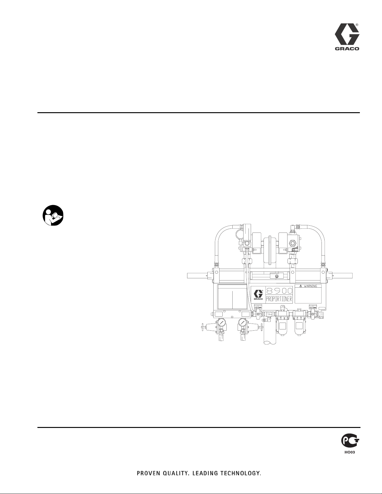
8900 Proportioner
309790ZAA
Configured product offering for dispensing fixed or variable ratio of two
fluids. For professional use only.
Not approved for use in European explosive atmosphere locations.
2000 psi (13.8 MPa, 138 bar) Maximum Working Pressure
Important Safety Instructions
Read all warnings and instructions in this manual.
Save these instructions.
See page 8 for pump model numbers, ratios and
working pressures.
ENG
Fixed-ratio proportioner shown
TI2761A
Page 2

Contents
Warnings . . . . . . . . . . . . . . . . . . . . . . . . . . . . . . . . . 4
Theory of Operation . . . . . . . . . . . . . . . . . . . . . . . . 6
Use . . . . . . . . . . . . . . . . . . . . . . . . . . . . . . . . . . . 6
Major Components . . . . . . . . . . . . . . . . . . . . . . . 6
Ratio Proportioning . . . . . . . . . . . . . . . . . . . . . . . 6
System Components and Operation Overview . . 6
Models . . . . . . . . . . . . . . . . . . . . . . . . . . . . . . . . . . . 8
Installation . . . . . . . . . . . . . . . . . . . . . . . . . . . . . . . 10
Typical Installation . . . . . . . . . . . . . . . . . . . . . . . 10
Location . . . . . . . . . . . . . . . . . . . . . . . . . . . . . . 10
Ground . . . . . . . . . . . . . . . . . . . . . . . . . . . . . . . 12
Flush . . . . . . . . . . . . . . . . . . . . . . . . . . . . . . . . . 13
Setup . . . . . . . . . . . . . . . . . . . . . . . . . . . . . . . . . . . . 14
Set the Ratio (variable ratio models only) . . . . . 14
Output Charts/Ratio Settings . . . . . . . . . . . . . . 15
Before You Load Material . . . . . . . . . . . . . . . . . 18
Load Component A . . . . . . . . . . . . . . . . . . . . . . 19
Prime Pump A . . . . . . . . . . . . . . . . . . . . . . . . . . 20
Load Component B . . . . . . . . . . . . . . . . . . . . . . 21
Prime with Component B . . . . . . . . . . . . . . . . . 24
Fill the 8900 Proportioner with Material . . . . . . 24
Operation . . . . . . . . . . . . . . . . . . . . . . . . . . . . . . . . 27
Pressure Relief Procedure . . . . . . . . . . . . . . . . 27
Dispense Mixed Material . . . . . . . . . . . . . . . . . . 28
Changing Component A Drum . . . . . . . . . . . . . 30
Changing Component B Pail . . . . . . . . . . . . . . . 31
Filling Component B Pressure Tank . . . . . . . . . 32
Daily Procedures . . . . . . . . . . . . . . . . . . . . . . . . 34
Troubleshooting . . . . . . . . . . . . . . . . . . . . . . . . . . . 36
8900 Proportioner Operating Pressures . . . . . . 36
Air Supply Troubleshooting Chart . . . . . . . . . . . 37
Pump Troubleshooting Overview . . . . . . . . . . . 38
Troubleshooting Guide: Feed pumps . . . . . . . . 39
Troubleshooting Guide: 8900 Proportioner . . . . 40
Troubleshooting Guide: Manifold/Mixer . . . . . . . 41
Preventive Maintenance . . . . . . . . . . . . . . . . . . 42
Service and Repair . . . . . . . . . . . . . . . . . . . . . . . . 43
Repair the Cylinder (Fixed Ratio) . . . . . . . . . . . 43
Replace Air Valve . . . . . . . . . . . . . . . . . . . . . . . 45
Disassemble Fluid Valve . . . . . . . . . . . . . . . . . . . . 46
Parts . . . . . . . . . . . . . . . . . . . . . . . . . . . . . . . . . . . . 48
8900 Proportioner, Fixed Ratio . . . . . . . . . . . . . 48
8900 Proportioner, Variable Ratio . . . . . . . . . . . 50
Cylinder Assemblies . . . . . . . . . . . . . . . . . . . . . 52
Limit Valve . . . . . . . . . . . . . . . . . . . . . . . . . . . . . 53
Air Control . . . . . . . . . . . . . . . . . . . . . . . . . . . . . 54
4-Way Valve . . . . . . . . . . . . . . . . . . . . . . . . . . . . 55
Pump Feed Module Selection for Component A or
Component B . . . . . . . . . . . . . . . . . . . . . . . 56
20:1 President on 5 Gallon Ram . . . . . . . . . . . . 56
34:1 Senator on 5 Gallon Ram . . . . . . . . . . . . . 58
23:1 Monark on 5 Gallon Ram . . . . . . . . . . . . . 60
20:1 President on 55 Gallon Ram . . . . . . . . . . . 62
34:1 Senator on 55 Gallon Ram . . . . . . . . . . . . 64
31:1 Bulldog on 55 Gallon Ram . . . . . . . . . . . . . 65
20:1 Senator on 55 Gallon Drum . . . . . . . . . . . . 66
9:1 DynaMite on 1 Gallon Can Ram . . . . . . . . . 67
10 Gallon Press Tank with 15:1 Booster . . . . . . 68
10:1 President 5 Gallon Pail Cover . . . . . . . . . . 69
Mix Kit Selection . . . . . . . . . . . . . . . . . . . . . . . . 70
Cartridge Fill Medium Viscosity Wide Ratio . . . 70
Cartridge Fill High Viscosity Wide Ratio . . . . . . 72
Brush Grade High Viscosity Wide Ratio . . . . . . 74
MD2 20 ft Automatic . . . . . . . . . . . . . . . . . . . . . 76
MD2 20 ft Hand Gun . . . . . . . . . . . . . . . . . . . . . 77
MD2 15 ft Hand Gun Wide Ratio Moisture Lock 78
High Volume Static Mix Manifold . . . . . . . . . . . . 79
High Volume Static Mix Kit with Pump Pilots . . . 80
Stanchion . . . . . . . . . . . . . . . . . . . . . . . . . . . . . . 81
Boom Assembly . . . . . . . . . . . . . . . . . . . . . . . . . 82
Technical Data . . . . . . . . . . . . . . . . . . . . . . . . . . . . 84
Graco Standard Warranty . . . . . . . . . . . . . . . . . . . 86
Graco Information . . . . . . . . . . . . . . . . . . . . . . . . . 86
2 309790ZAA
Page 3

309790ZAA 3
Page 4
Warnings
Warnings
Skin Injection Hazard
Spray from the gun, hose leaks, or ruptured components can inject fluid through skin and cause
extremely serious injury, including need for amputation. Fluid splashed in the eyes or on skin can cause
serious injury.
• Fluid injected into skin might look like just a cut, but it is a serious injury. Get immediate surgical
• Do not point the gun at anyone or any part of the body.
• Do not put hand or fingers over the spray tip/nozzle.
• Do not stop or deflect leaks with hand, body, glove or rag.
• Do not “blow back” fluid; this is not an air spray system.
• Always have tip guard and trigger guard on the gun when spraying.
• Check gun diffuser weekly. Refer to gun manual.
Warning
treatment.
• Check trigger safety operation before spraying. Lock trigger safety when you stop spraying.
• Follow the Pressure Relief Procedure, page 27, if the spray tip/nozzle clogs and before cleaning,
checking or servicing the equipment.
• Tighten fluid connections before operating equipment.
• Check hoses, tubes, and couplings daily. Replace worn or damaged parts immediately. Do not repair
high pressure couplings; replace the entire hose.
• Fluid hoses must have spring guards on both ends to help protect them from rupture caused by kinks
or bends near the couplings.
Toxic Fluid Hazard
Hazardous fluids or toxic fumes can cause serious injury or death if splashed in the eyes or on skin, swallowed, or inhaled.
• Know specific hazards of the fluid. Read fluid manufacturer’s warnings.
• Wear appropriate protective clothing, gloves, eyewear, and respirator.
4 309790ZAA
Page 5
Warnings
Warning
Equipment Misuse Hazard
Equipment misuse can cause equipment to rupture, malfunction, or start unexpectedly and cause serious
injury.
• This equipment is for professional use only.
• Read manuals, tags, and labels before operating equipment.
• Use equipment only for its intended purpose. If you are uncertain, call your Graco distributor.
• Do not alter or modify equipment. Use only genuine Graco parts and accessories.
• Check equipment daily. Repair or replace worn or damaged parts immediately.
• Do not exceed maximum working pressure of lowest rated system component.
• Use fluids and solvents that are compatible with equipment wetted parts. See Technical Data sec-
tion of all equipment manuals. Read fluid and solvent manufacturer’s warnings.
• Route hoses away from traffic areas, sharp edges, moving parts, and hot surfaces. Do not expose
Graco hoses to temperatures above 180°F (82°C) or below -40°F (-40°C).
• Do not kink or overbend hoses or use hoses to pull equipment.
• Comply with all applicable local, state, and national fire, electrical, and other safety regulations.
• Do not use excessive drum separation air pressure as the drum could rupture. Make sure the drum is
not damaged and the ram plate is free to exit the drum before applying air pressure.
Fire and Explosion Hazard
Improper grounding, poor ventilation, open flames or sparks can cause a hazardous condition and result
in fire or explosion and serious injury.
• Ground the equipment and object being sprayed. See Grounding, page 12.
• If you experience static sparking or electric shock, stop operation immediately. Identify and correct
the problem.
• Provide fresh air ventilation to avoid building up flammable fumes.
• Keep the spray area free of debris, including solvent, rags, and gasoline.
• Extinguish all sources of flames in the spray area, including pilot lights and cigarettes.
• Do not turn on or off any light switch or plug or unplug electrical equipment in the spray area while
operating or if fumes are present.
• Do not operate a gasoline engine in the spray area.
• Keep a fire extinguisher in the work area.
Moving Parts Hazard
Moving parts, such as priming piston and wiper plate, can pinch or amputate fingers. Keep clear of moving parts when starting or operating equipment and when equipment is pressurized.
• Keep hands and fingers away from the priming piston.
• Keep hands away from the ram wiper plate and pail lip.
• Before servicing, follow the Pressure Relief Procedure, page 27, to avoid equipment startup.
309790ZAA 5
Page 6

Theory of Operation
Theory of Operation
Use
The 8900 Proportioner is used with two component
materials where one or both components is high viscosity. This is typically found in the sealant and adhesive
industry, where special requirements for loading and
pumping necessitate the use of the 8900 proportioning
system.
Major Components
The major components of the 8900 Proportioner system
include the:
• Component A or major volume metering cylinder
• Component B or minor volume metering cylinder
• Component A or major volume feed supply
• Component B or minor volume feed supply
Ratio Proportioning
The A and B cylinders are positive displacement metering cylinders. Positive displacement cylinders displace a
defined volume of fluid for a given stroke length.
On fixed ratio units, the volumetric ratio is the ratio of the
area of the component A displacement cylinder to the
area of the component B displacement cylinder. At a 1:1
ratio, the displacement cylinders are the same size. On
higher ratio units the component A cylinder is usually the
larger of the two. The ratio of the components is the difference in effective area between the cylinders.
On variable ratio units, the component B cylinder has an
adjustable stroke length. The component A cylinder has
a fixed stroke length. By setting the stroke adjustment to
different points on the connecting linkage, you can
change the stroke length of the B cylinder, which
changes the mix ratio. You can calculate the material
mix ratio from the ratio of the cylinder displacement volume.
System Components and Operation Overview
Feed Systems - Feed Pumps
Load the Feed Pumps and Proportioner
The A and B feed pumps/cylinders must completely fill
(prime) on both strokes to ensure accurate material displacement.
With high viscosity materials, it is difficult for material to
flow into the pump. Individual feed pumps are used to
supply these materials under pressure to the 8900 Proportioner. When air is trapped in the feed system due to
improper loading, a condition called cavitation occurs.
If cavitation occurs, part of the downstroke will be used
to fill the vacuum before any material is actually displaced. Since the total stroke length is used to calculate
mix ratio, this may result in an off-ratio condition.
To prevent cavitation with higher viscosity materials,
both cylinders are pressure fed. The A pump is pressurized by a pneumatic ram supply unit applying a downward force on a 55-gallon plate fitted into the drum. A
shovel action pump fluid inlet further aids in pump priming. Component B is delivered to the B pump by pressure fed 5- or 55-gallon supply modules, depending on
the volumetric ratio of the material.
Pneumatic ram assisted feed pumps may not be
required for lower viscosity materials.
Feed Systems - Alternative Feed Supplies
Header or other feed systems may be used to supply A
and B materials to the 8900 Proportioner. Generally
these feed systems are provided by others and are not
addressed in this manual. This manual applies only to
the Graco Configured 8900 Proportioner system.
Note that the mix ratio of the 8900 Proportioner is
achieved by volumetric ratio of component A to component B and not by weight. These two ratios are often different depending on material properties.
6 309790ZAA
Page 7

Theory of Operation
Pump Fluids to the Mixer
Fluid is pumped through the proportioner to a mix chamber or to a 2-component dispense gun, where component A and component B are first introduced before
being mixed with a static mixer.
A fluid injector nozzle/check valve injects component B
into component A at the mix chamber. When enough
pressure builds up, the check valve opens and component B flows into the mix chamber. This means that during flow conditions with two positive displacement
cylinders linked together, the pressures at the mix point
are equal.
Any pressure differences noted on the gauges while
running, reflect differences in the pressure lost by each
fluid getting from the gauge to the mix point. These
pressure drops are caused by hoses and fittings in conjunction with material viscosity.
Mix the Fluids
Both components leave the mix chamber and enter a
static mixer where they are mixed to a homogeneous
blend. The mixer consists of a series of left and
right-hand spiral elements. This is true for both mix
chamber and 2-component mix gun.
Some 8900 Proportioners use a 2K disposable mixer
element dispense valve instead of the flow gun.
The 8900 Proportioner can be used in automatic
assembly lines with the addition of a logic interface.
When the components are pumped through the mixer,
they are progressively divided and recombined. Static
mixers used on the 8900 Proportioner system include
the tri-core mixer, flexible hose mixer, or disposable
mixer.
Ratio Checks
On the variable ratio model, a ratio check station option
verifies the volumetric mix ratio of the two components.
It is located at the outlet blocks. With all outbound fluid
valves closed, each component flows through individual
ball valves opened by a common handle into containers.
Volumetric mix ratio can be calculated from the weight of
each component or by direct measurement. Ratio
checks are performed with the back pressures set to
actual operating pressures to simulate the normal back
pressures created by the mix chamber and gun.
Dispense Valve
An extrusion flow gun is commonly used as the applica-
tion device. It has a final or clean up mixer installed in
the handle. Various extrusion nozzles are available for
caulking or sealing applications.
309790ZAA 7
Page 8

Models
Models
Refer to form 684041 for selection information.
Model Description
890-D Power Valved Passive Proportioner
Code A Proportioner Selection (“A” Cyl. / “B” Cyl.) Module Number
1 1:1 Fixed (1000/1000) 570371
2 2:1 Fixed (1000/500) 570372
3 2.5:1 Fixed (250/100) 570373
4 4:1 Fixed (1000/250) 570374
5 5:1 Fixed (500/100) 570375
6 10:1 Fixed (1000/100) 570376
7 9:1 Fixed (1000/111) 246557
A 1:1 to 4:1 Variable (500/500) 570377
B 2:1 to 8:1 Variable (500/250) 570378
D 5:1 to 20:1 Variable (500/100) 570380
Code B Pump Feed Module Selection for Component A Module Number
A 20:1 President on 5 Gallon Ram 965571
B 34:1 Senator on 5 Gallon Ram 965597
C 23:1 Monark on 5 Gallon Ram 570142
D 20:1 President on 55 Gallon Ram 570114
E 34:1 Senator on 55 Gallon Ram 965572
F 31:1 Bulldog on 55 Gallon Ram 570141
G 20:1 Senator on 55 Gallon Drum 570309
H 9:1 DynaMite 1 Gallon Can Ram 570249
J 10 Gallon Press Tank with 15:1 Booster 570037
K 10:1 President 5 Gallon Pail Cover 570264
NNone
Code C Pump Feed Module Selection for Component B Module Number
A 20:1 President on 5 Gallon Ram 965571
B 34:1 Senator on 5 Gallon Ram 965597
C 23:1 Monark on 5 Gallon Ram 570142
D 20:1 President on 55 Gallon Ram 570114
E 34:1 Senator on 55 Gallon Ram 965572
F 31:1 Bulldog on 55 Gallon Ram 570141
G 20:1 Senator on 55 Gallon Drum 570309
H 9:1 DynaMite 1 Gallon Can Ram 570249
J 10 Gallon Press Tank with 15:1 Booster 570037
K 10:1 President 5 Gallon Pail Cover 570264
NNone
8 309790ZAA
Page 9

Code D Mix Kit Selection Module Number
1 Cart Fill Medium Viscosity Wide Ratio 570248
2 Cart Fill High Viscosity Wide Ratio 570318
3 Brush Grade High Viscosity Wide Ratio 570358
4 MD2 20 ft Automatic Wide Ratio 24H258
5 MD2 20 ft Automatic Close Ratio 24H259
6 MD2 20 ft Hand Gun Wide Ratio 24H260
7 MD2 20 ft Hand Gun Close Ratio 24H261
8 MD2 15 ft Hand Gun Wide Ratio Moisture Lock 24H243
9 High Volume Static Mix Kit with Pump Pilots 570263
NNone
Code E Mounting Type Selection Module Number
1 Stanchion 570071
2 Boom Assembly 246589
N None (mount on 3 in. 55 gallon ram)
Models
309790ZAA 9
Page 10
Installation
Installation
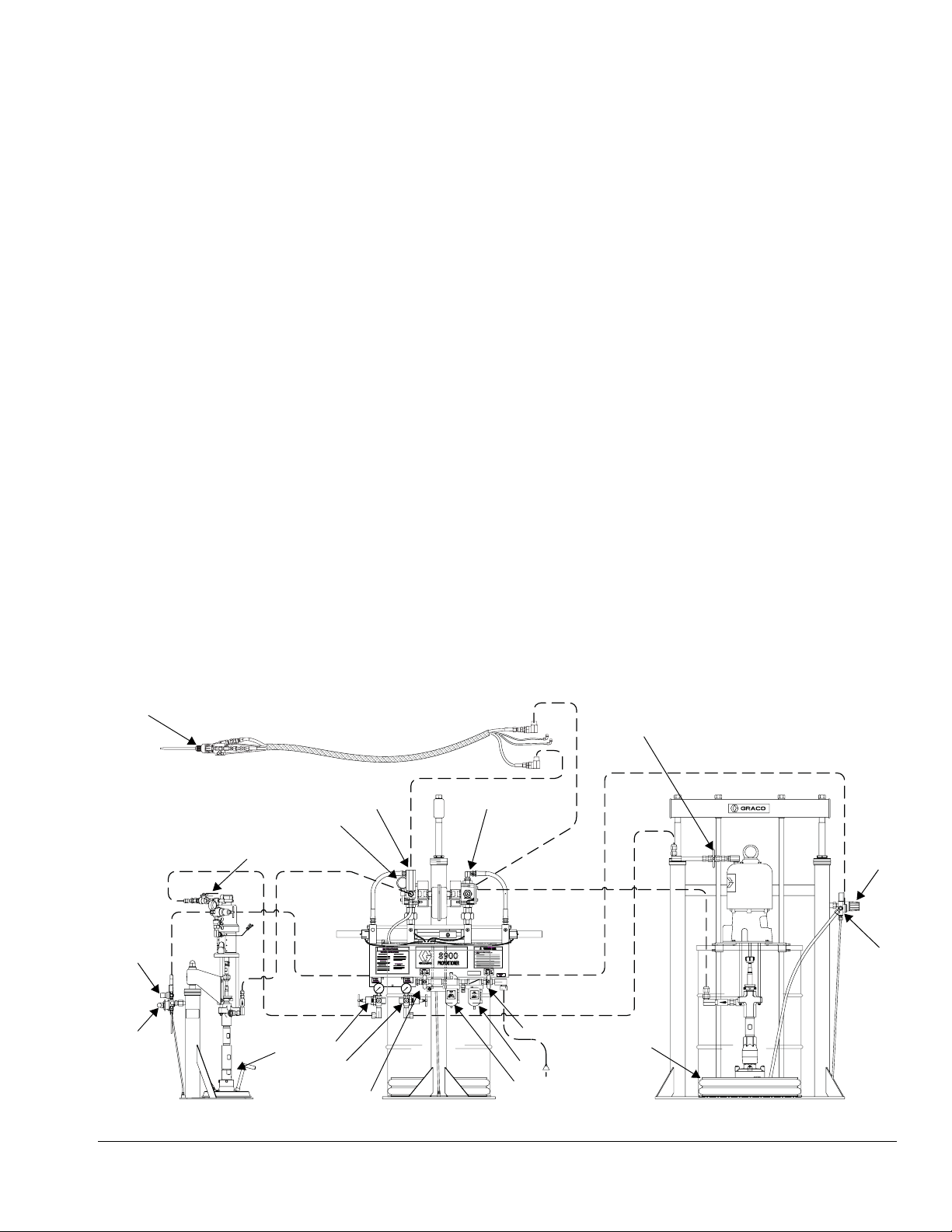
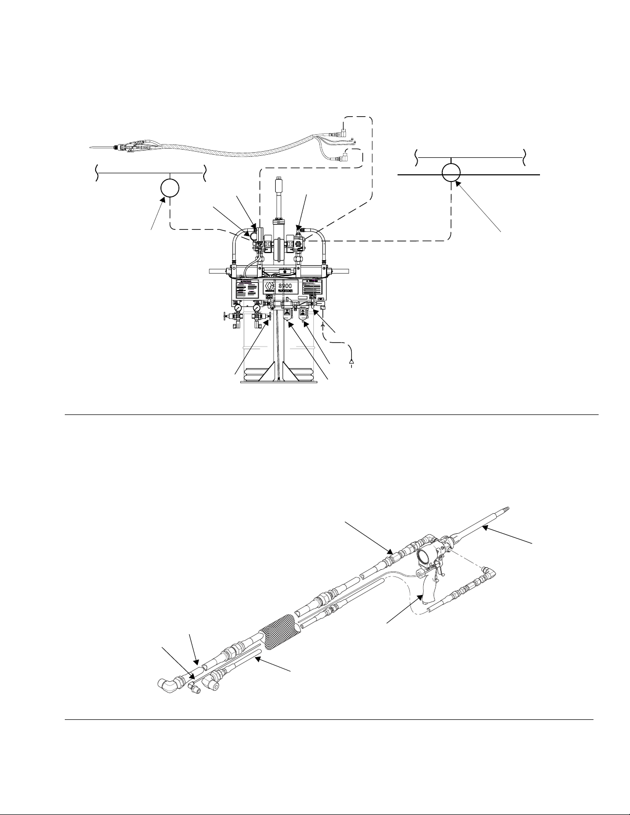
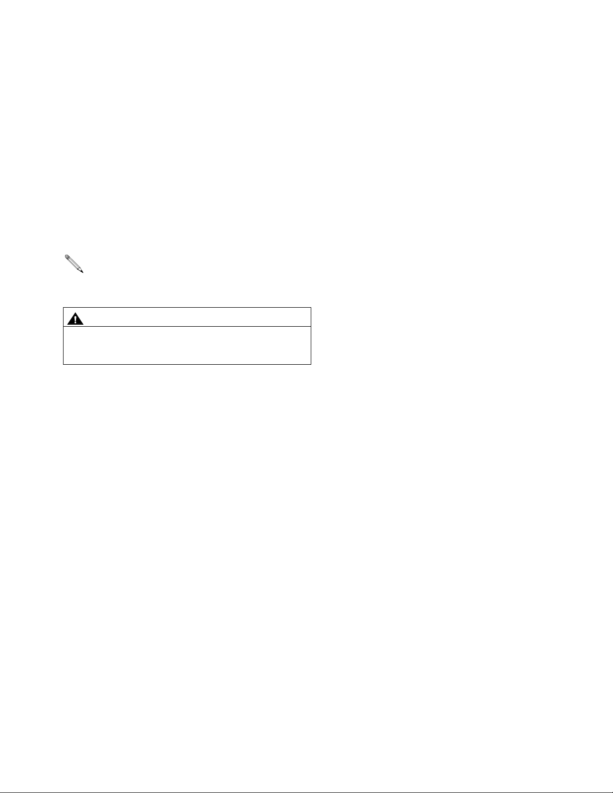
Typical Installation
Figures 1-3 are only guides for selecting and installing system components and accessories. Contact your
Graco distributor for assistance in designing a system to suit your needs.
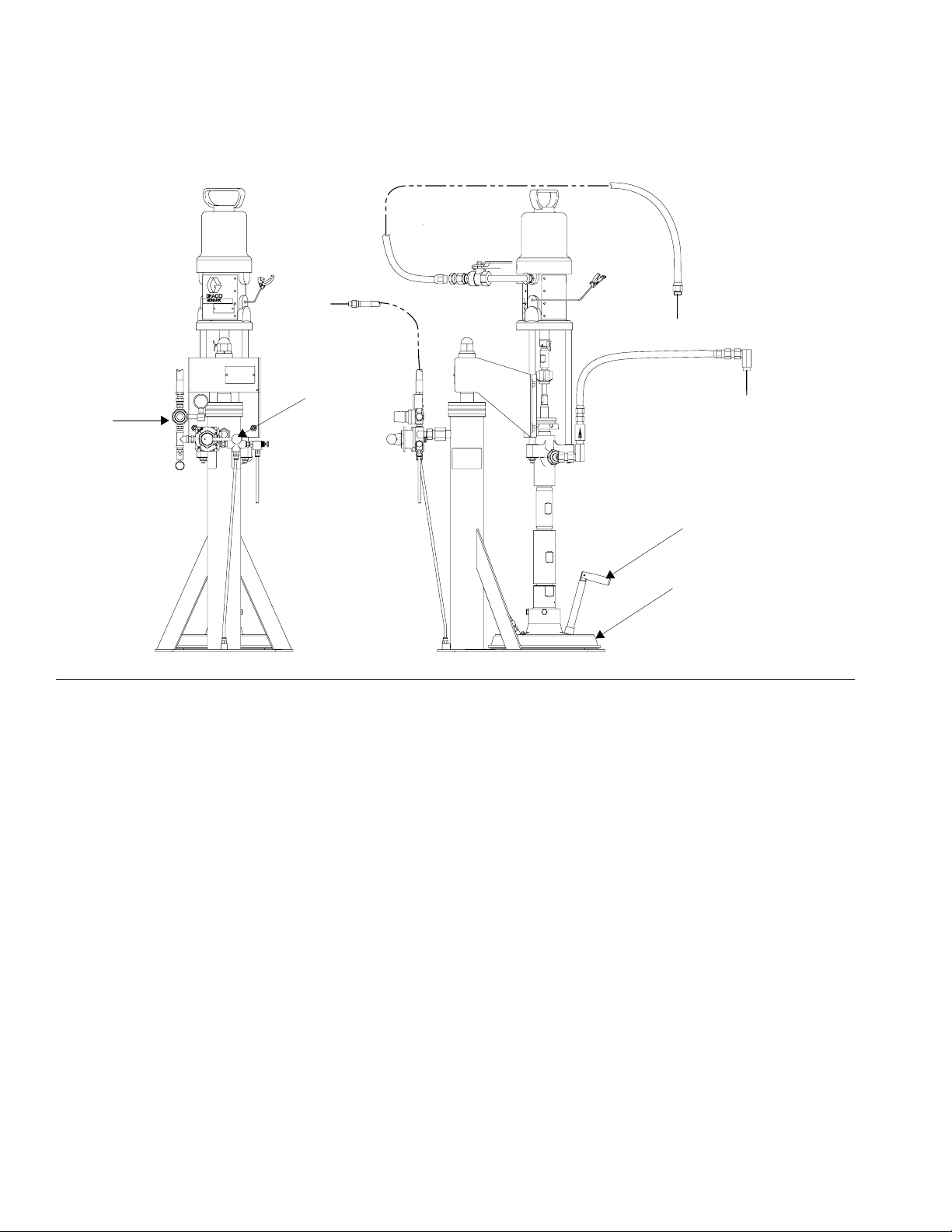
Location
Position the feed modules so the pump and ram are
easily accessible. Ensure that there is sufficient overhead clearance when the ram is fully raised. Refer to
the ram manual for clearance dimensions.
Using the holes in the ram base as a guide, drill four
holes for 1/2 in. (13 mm) anchors.
Key:Figs. 1 and 2
A System Air Shutoff Valve (bleed-type)
B Main Air Filter
C Component B Ram Directional Valve
D Component B Ram Air Pressure Regulator
E Component B Air Supply Valve (bleed-type)
F Component B Air Supply Regulator
G Component A Air Supply Valve
H Component B Outlet Pressure Gauge
J Component B Feed Pressure Gauge
K Component A Feed Pressure Gauge
Q
J
(behind)
H
Check that the ram base is level in all directions. If
necessary, level the base using metal shims. Secure
the base to the floor using 1/2 in. (13 mm) anchors
that are long enough to prevent the ram from tipping.
L Component A and Component B Feed Pump Air
Motor Lubricator
M Component B Ram Plate with Vent Stick or Valve
N Component A Ram Plate with Drum Vent Valve
O Component A Pump Air Regulator
P Component A Ram Directional Valve
Q MD2 Gun with Disposable Mixers
R Component A Ram Air Pressure Regulator
S Accessory/Gun Air Supply Valve
G
K
(behind)
E
WARNINGWARNING
WARNINGWARNING
INSTRUCTIONS
INSTRUCTIONS
READ MANUAL BEFORE OPERATING
D
C
M
F
DISPENSE MIXED MATERIAL
ADJUST FLOW RATE
DRUM OR PAIL CHANGE
"B" PUMP
PRESSURE
ADJUSTMENT
R
BASE PURGE AND SHUT-DOWN
REFILLING PRESSURE POT
(IF EQUIPPED)
PUMPS
ONOFF
"A" PUMP
PRESSURE
ADJUSTMENT
O
8900
PROPORTIONER
WARNINGWARNING
High pressure device for professional use only.
Read instruction manual before operating. Observe all
warnings.
MAIN AIR
OFF ON
MAIN AIR
INLET
A
N
B
L
S
FIG. 1:
10 309790ZAA
R
P
ti16735a
Page 11
Installation
Supply header system supplied by others
(not covered in this manual).
Component B
Supply Header
Component B
Fluid Regulator
FIG. 2:
Key:FIG. 3
Q2K Gun
V Disposable Mixer Element
W Component B Injector Valve
H
J
(behind)
INSTRUCTIONS
INSTRUCTIONS
READ MANUAL BEFORE OPERATING
DISPENSE MIXED MATERIAL
ADJUST FLOW RATE
DRUM OR PAIL CHANGE
"B" PUMP
PRESSURE
ADJUSTMENT
S
K
(behind)
Component A
Supply Header
Component A
Fluid Regulator
WARNINGWARNING
WARNINGWARNING
8900
PROPORTIONER
WARNINGWARNING
High pressure device for professional use only.
Read instruction manual before operating. Observe all
warnings.
MAIN AIR
OFF ON
MAIN AIR
INLET
R
BASE PURGE AND SHUT-DOWN
REFILLING PRESSURE POT
(IF EQUIPPED)
PUMPS
ONOFF
"A" PUMP
PRESSURE
ADJUSTMENT
A
B
L
ti16759a
X Air Trigger Pilot
Y Component B Supply
Z Component A Supply
W
V
Y
Q
X
Z
ti16737a
FIG. 3
309790ZAA 11
Page 12
Installation
Ground
WARNING
The system must be properly grounded. Read warnings, page 5. Follow the instructions below.
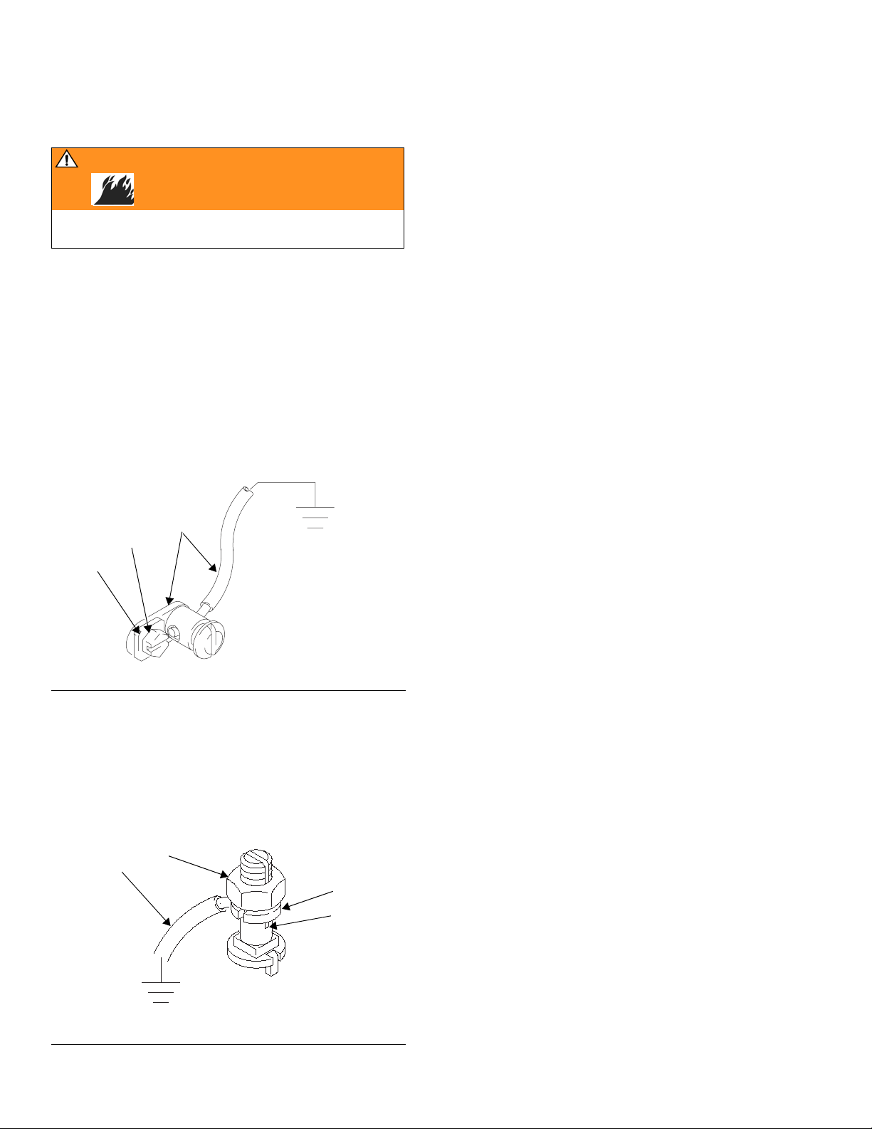
Pump: use the ground wire and clamp (supplied). There
are two styles of ground connections on pump air
motors.
If you have the ground screw (a) shown in F
(King air motor only), order part no. 222011 ground wire,
ring terminal, and clamp assembly (b). To install
222011, remove the ground screw (a) and insert it
through the eye of ring terminal (c), then tighten ground
screw back into air motor as shown in F
IG. 4. Connect
the other end of the wire to a true earth ground.
b
a
c
IG. 4
Air and fluid hoses: use only electrically conductive
hoses with a maximum of 500
ft (150 m) combined hose
length to ensure grounding continuity. Check the electrical resistance of your air and fluid hoses. If the total
resistance to ground exceeds 29 megohms, replace the
hose immediately.
Air compressor: follow manufacturer’s recommendations.
Spray gun/dispense valve: ground through connection
to a properly grounded fluid hose and pump.
Fluid supply container: follow your local code.
Substrate: follow your local code.
Solvent pails used when flushing: follow your local
code. Use only conductive, metal pails, placed on a
grounded surface. Do not place the pail on a nonconductive surface, such as paper or cardboard, which
interrupts grounding continuity.
To maintain grounding continuity when flushing or
relieving pressure: hold a metal part of the gun/dis-
pense valve firmly to the side of a grounded metal pail,
then trigger the gun/valve.
IG. 4: Ground Screw (King air motors only)
F
If you have the ground screw (d) shown in F
IG. 5,
loosen the grounding lug locknut (g) and washer (f).
Insert one end of the ground wire (e) into the slot in lug
(d) and tighten the locknut securely. Connect the other
end of the wire to a true earth ground. Order 237569
ground wire and clamp assembly.
e
g
f
d
IG. 5 Ground Screw
F
12 309790ZAA
Page 13
Installation
Flush
WARNING
Read warnings, pages 4-5. Follow Ground instructions, page 12.
• The equipment was tested with light, soluble oil.
Flush the system before loading material to avoid
contamination.
• Flush at the lowest pressure possible and check
connectors for leaks.
To flush the system:
1. On the ram-mounted component A supply units, you
must remove the drum ram plate to immerse the A
pump in a solvent pail. To remove the plate:
a. Disconnect the blow-off air line from the ram
plate.
b. Disconnect the tie rod nuts from the ram cross
beam.
2. Flush the system and all hoses by very slowly opening the motor control valves until 30 psi (207 kPa,
2.1 bar) is shown on the component A outlet pressure gauge.
Flush for 1-2 minutes, then close the motor control
valves.
CAUTION
To avoid damaging the pump, open the motor control
valves very slowly to prevent a pump runaway condition.
It is normal for the air valve to exhaust air when it is
partially open.
3. Check connectors for leaks and tighten them if necessary.
4. Remove the solvent pail(s) from the pump inlets.
5. Operate the pump(s) at low pressure to remove
excess solvent.
6. Reinstall the drum or pail ram plates.
c. Remove seal plates between the pump and
ram.
d. Loosen ram tie rods from plate and remove
plate.
e. If a pail ram is used with the component B sup-
ply, remove the pail plate by loosening the 2 set
screws.
f. Position the solvent pail so the pump inlet is in
the solvent.
Use solvent that is compatible with the equipment
wetted parts and the material you will dispense.
g. Support the ram(s) so that the pump inlet and
piston will not hit the base plate or pail bottom.
h. Make sure both component A and component B
outlet hoses are open.
309790ZAA 13
Page 14
Setup
Setup
WARNING
Read warnings, pages 4-5, before operating equipment.
Set the Ratio (variable ratio models only)
Adjust ratio
The ratio of this unit is produced partially by the difference in the area of the metering cylinders and partially
by the position of the adjustable fulcrum point in the Unibar linkage assembly. With the fulcrum point in the center, each meter cylinder strokes 3 in. (10.16 cm). In the
center position, the dispense ratio is the same as the
meter cylinder ratio.
The linkage is adjustable depending on the location of
the fulcrum point. The linkage must be adjusted for each
material application so the combined linkage and meter
cylinder ratio equals the desired material mix ratio by
volume. The ratio may be checked by weight, but the
machine meters by volume and that ratio must be known
before proceeding.
The initial linkage adjustment point can be calculated by
inserting known values into the formula on page 35. The
result is the distance in inches from the center of the fulcrum point to the center of the component B meter cylinder. For convenience, measure the distance between
the grease fitting on the top of the fulcrum and the center of the component B cylinder meter rod.
a
e
r
c
n
I
e
m
u
l
o
V
e
B
s
a
e
r
c
e
FIG. 6
Set Scale
Refer to the 8900 Proportioner Output Charts on the following pages to set the scale. Make final adjustments
after the material is loaded. See instructions on page 33
for detailed ratio check instructions.
e
s
14 309790ZAA
Page 15
Output Charts/Ratio Settings
g
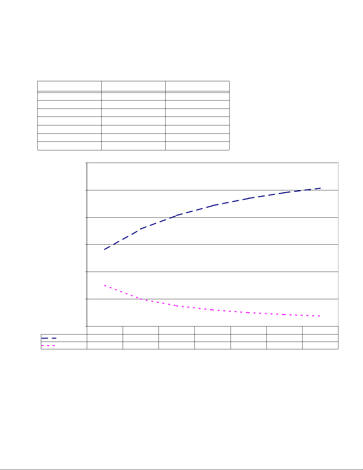
8900 Proportioner, 1:1 - 4:1 Variable Ratio
Mix Ratio by Volume Scale Setting Minor Stroke
1 5.63 3.00
1.5 7.13 2.00
2 8.13 1.50
2.5 8.85 1.20
3 9.38 1.00
3.5 9.80 0.86
4 10.13 0.75
12
10
Setup
Setting in Inches from Pivot or Minor Stroke
Mix Ratio by Volume
Scale Settin
Minor Stroke
8
6
4
2
0
1 1.5 2 2.5 3 3.5 4
5.63 7.13 8.13 8.85 9.38 9.80 10.13
3.00 2.00 1.50 1.20 1.00 0.86 0.75
309790ZAA 15
Page 16
Setup
g
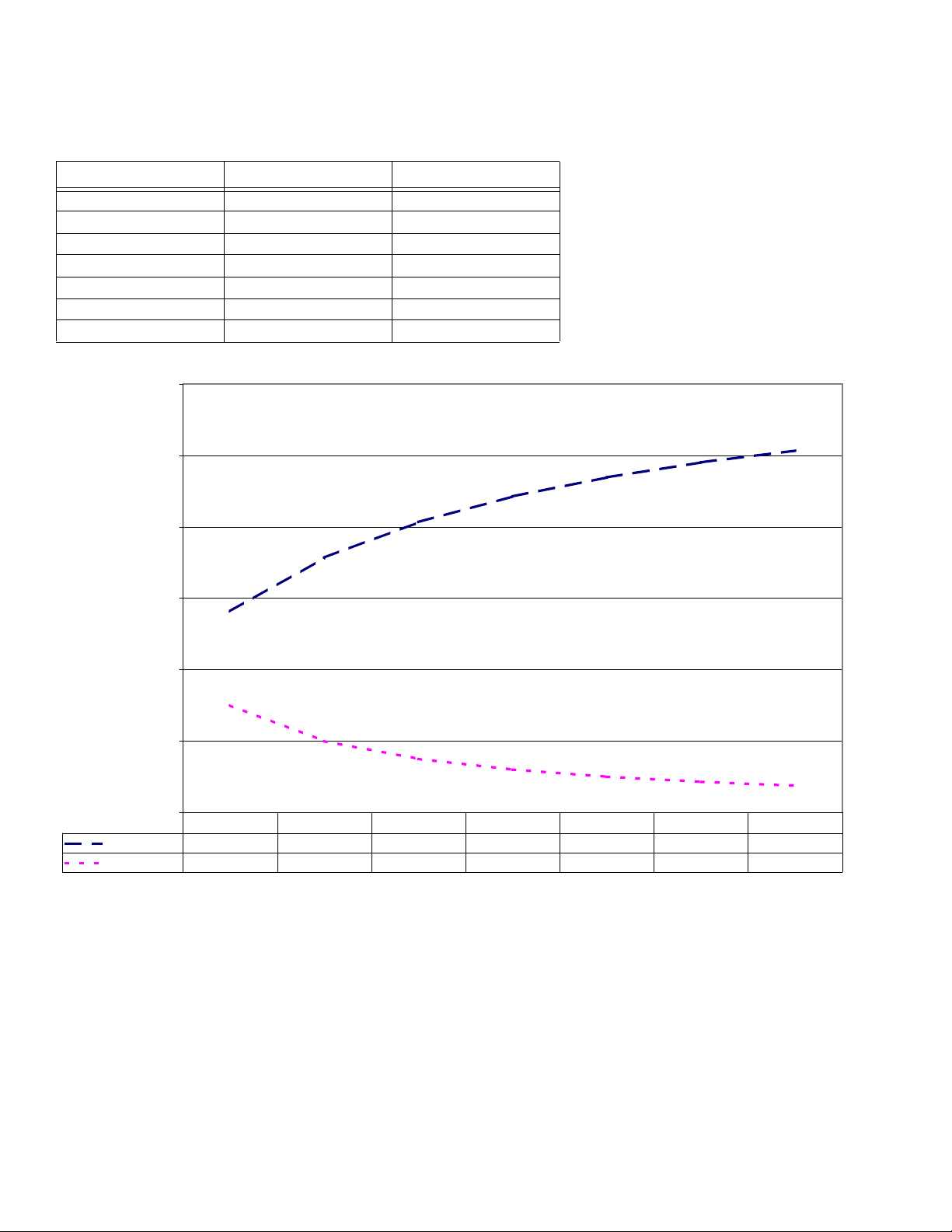
8900 Proportioner, 2:1 - 8:1 Variable Ratio
Mix Ratio by Volume Scale Setting Minor Stroke
2 5.63 3.00
3 7.13 2.00
4 8.13 1.50
5 8.85 1.20
6 9.38 1.00
7 9.80 0.86
8 10.13 0.75
12
10
Setting in Inches from Pivot or Minor Stroke
Mix Ratio by Volume
Scale Settin
Minor Stroke
8
6
4
2
0
2345678
5.63 7.13 8.13 8.85 9.38 9.80 10.13
3.00 2.00 1.50 1.20 1.00 0.86 0.75
16 309790ZAA
Page 17
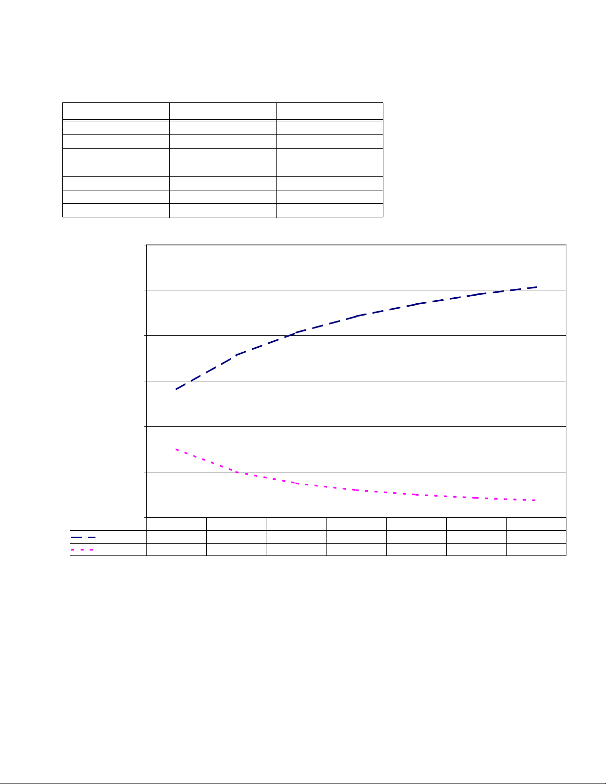
8900 Proportioner, 5:1 - 20:1 Variable Ratio
g
Mix Ratio by Volume Scale Setting Minor Stroke
5 5.63 3.00
7 7.13 2.00
10 8.13 1.50
12 8.85 1.20
15 9.38 1.00
17 9.80 0.86
20 10.13 0.75
12
10
Setup
Setting in Inches from Pivot or Minor Stroke
Mix Ratio by Volume
Scale Settin
Minor Stroke
8
6
4
2
0
5 7 10 12 15 17 20
5.63 7.13 8.13 8.85 9.38 9.80 10.13
3.00 2.00 1.50 1.20 1.00 0.86 0.75
309790ZAA 17
Page 18
Setup
Before You Load Material
1. Check fluid and air lines and tighten if necessary.
2. Make sure there is a minimum overhead clearance
of 110 in. (279 cm) for 55 gallon supply.
3. Fill air line lubricator for the 8900 Proportioner module with SAE 10 W non-detergent oil (not included).
4. Fill the pump A and B wet cups 2/3 full with Graco
T.S.L. fluid (throat seal lubricant) or lubricant compatible with material being pumped.
ISO pump oil is used with moisture sensitive component B.
5. Close (turn fully counterclockwise) all air regulators.
6. Connect the 3/4 in. (19 mm) ID x 10 ft (3.05 m) air
hose (provided) to your air supply.
Do not use a restrictive quick-disconnect. The air
supply pressure must be consistently above the
pressure you set on the main air motor regulator.
G
F
Wet Cup
N
TI3263Ax
IG. 7
18 309790ZAA
Page 19
Load Component A
1. Make sure all air regulators on proportioner module
are fully closed.
Setup
2. Open the main air supply shutoff valve (A), F
3. Place the ram lever (P-F
IG. 10) in the UP position.
IG. 8.
CAUTION
As the ram rises, make sure hoses do not catch on any
components. If a hose catches, immediately stop the
ram (move lever to NEUTRAL position) and correct the
problem. Lower the ram if necessary to redirect hoses.
4. Slowly turn the ram air regulator (R) clockwise until
the ram begins rising.
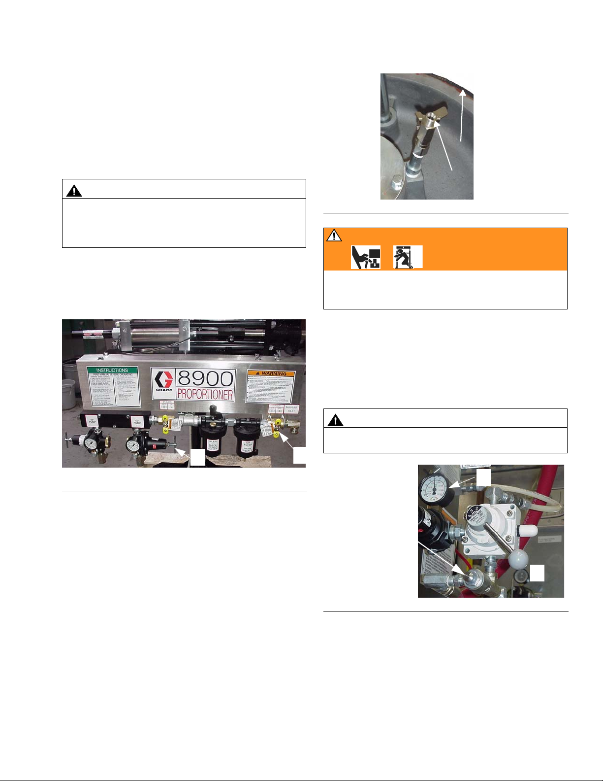
N
W
FIG. 9
WARNING
When lowering the ram, keep hands and body away
from the ram plate and material drum. Read warnings,
page 5.
9. With hands away from the pail and wiper plate (N),
set the ram lever (P-F
IG. 10) to NEUTRAL (horizon-
tal position). Let the ram lower until the wiper plate
rests on the pail lip.
10. Lower the ram plate into the drum (move ram lever
to DOWN position).
O
F
IG. 8
5. When ram is fully raised, apply a thin coating of
lubricant to the ram plate drum seals.
6. Open the material container. Remove any packing
materials, and inspect for material contamination. If
the container has a plastic liner, pull it tightly over
the sides of the container, and secure the liner in
place with tape wrapped below the top drum rim.
7. Position the drum so it rests evenly between the
centering guides and is fully backed into the stops
located near the back of the ram base plate.
8. Open the drum vent valve (W), F
IG. 9.
CAUTION
Do not lower ram if a drum is not in place. Doing so can
damage drum centering guides.
A
R
Ram Separation
Air Button
FIG. 10
11. After the ram plate seals contact the drum, adjust
the ram air regulator (R) to about 30-50 psi
(207-345 kPa, 2.1-3.4 bar).
12. When the ram stops and material fills the bleed port
(or air stops bleeding out), close the drum vent valve
(W), F
IG. 9.
P
13. Supply unit is now ready to fill lines to proportioner.
309790ZAA 19
Page 20
Setup
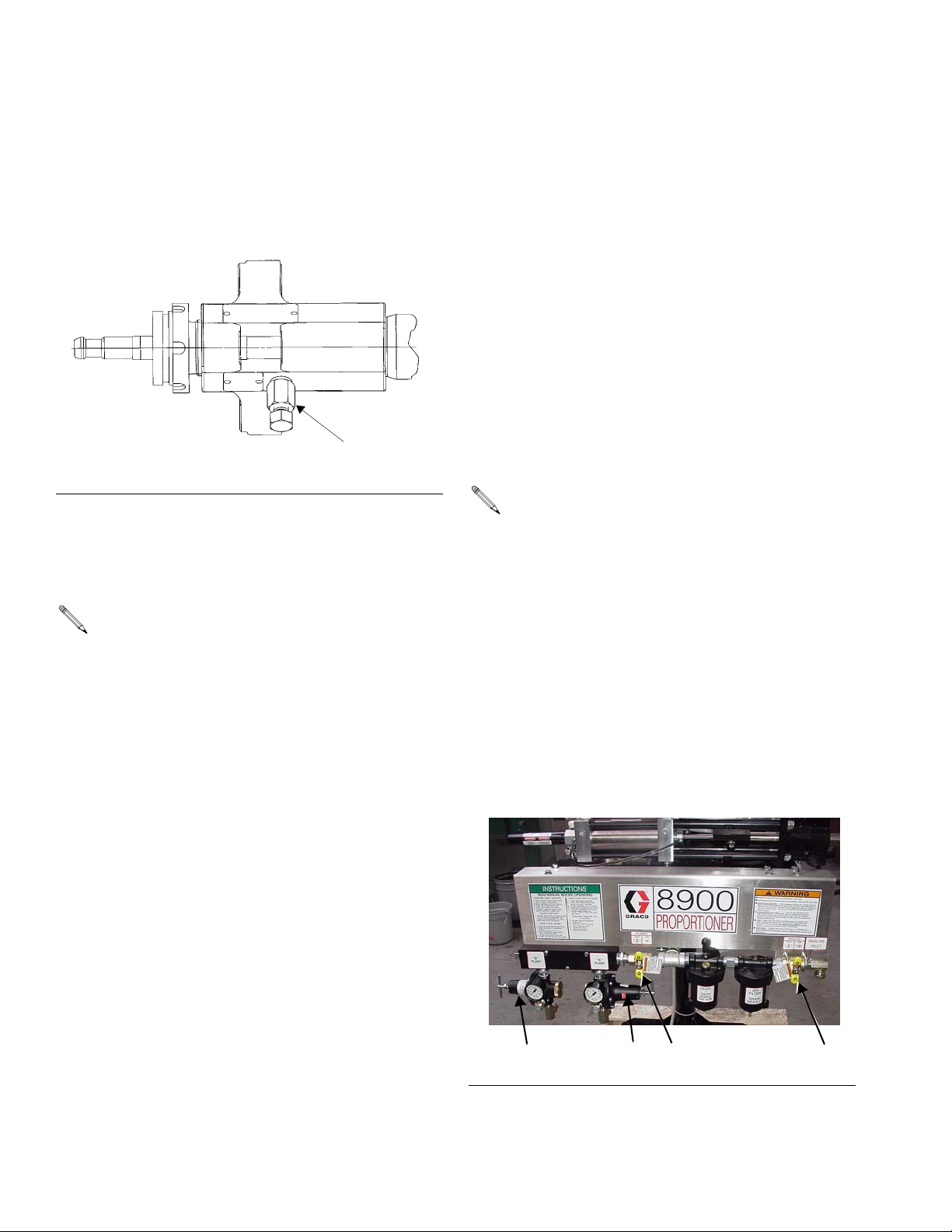
Prime Pump A
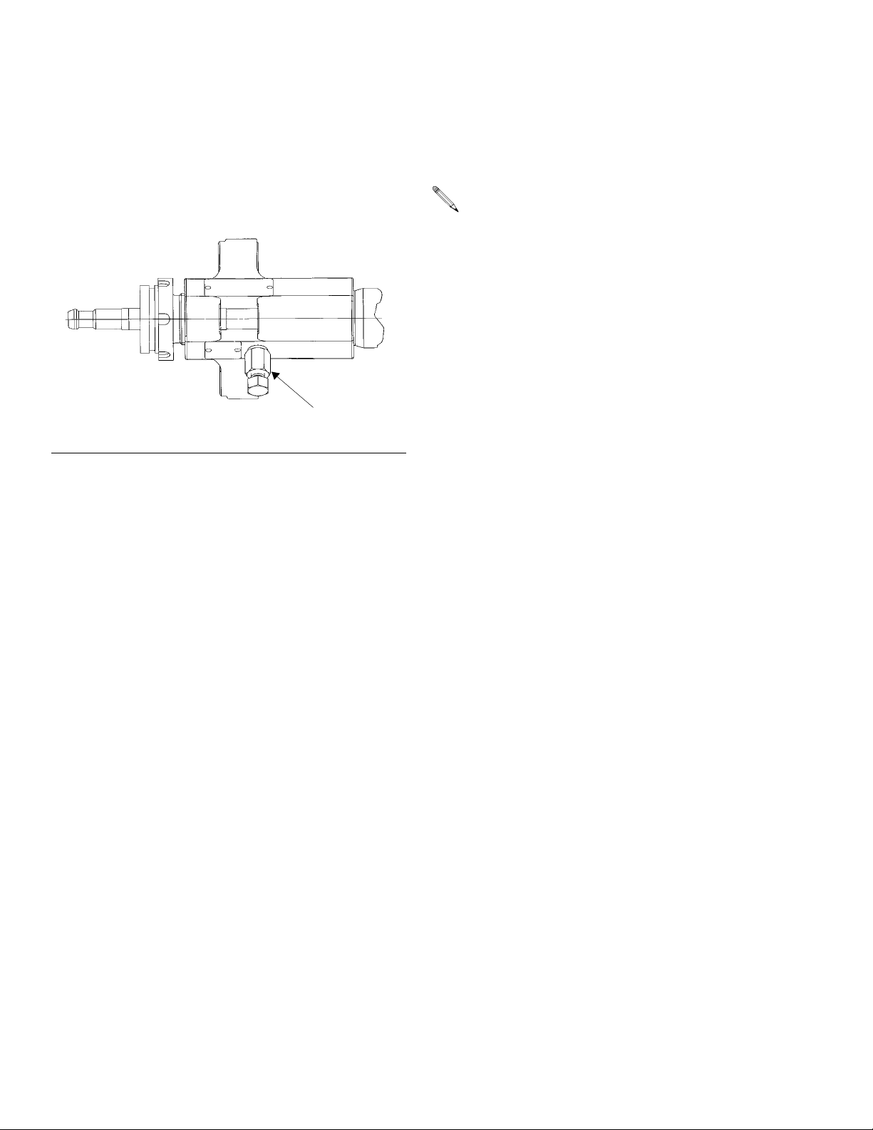
1. Place a waste container under the pump bleed valve
located behind the displacement pump outlet, F
11. Using an adjustable wrench, open the bleed
valve counterclockwise 1/3-1/2 turn.
Bleed Valve
F
IG. 11
IG.
2. Slowly open the component A air motor shutoff
valve (G), F
IG. 7. Make sure the pump begins to
cycle and material flows from the bleed valve after
several cycles of the pump, F
IG. 11.
If the pump does not cycle, close the air shutoff
valve (G), adjust the air motor regulator (O-F
IG. 8)
up 5 psi (34 kPa, 0.3 bar) and repeat step 2.
Never adjust the regulator by more than 5 psi (34
kPa, 0.3 bar) increments.
3. Operate the pump until it moves smoothly in both
directions with no air popping or erratic movement,
then close the air motor shutoff valve (G).
4. Close the bleed valve, F
IG. 11.
20 309790ZAA
Page 21

Setup
Load Component B
Follow the procedure for the type of supply equipment
being used.
Pneumatic Pail Ram and Piston Pump
1. Close all air regulators and air valves.
2. Set the pail ram air regulator (D) to 40 psi (0.28
MPa, 2.8 bar), F
3. Push the ram directional lever (C) to the UP position
and let the ram rise to its full height.
4. When ram is fully raised, apply a thin coating of
lubricant to the ram plate drum seals.
5. Remove the component B pail cover. If the material
has separated, carefully stir it with a metal or plastic
rod until it is mixed. Do not use wood to stir as it can
splinter and contaminate the material. Do not mix air
into the material.
6. Set the pail on the ram base. Slide it back toward
the ram tube and supports and center it under the
wiper plate. To prevent air from being trapped under
the wiper plate, scoop fluid from the center of the
pail to the sides to make the surface concave.
IG. 12.
WARNING
When operating the pump or raising or lowering the
ram, keep hands away from the wiper plate, fluid container lip, and pump intake. Read warnings, page 5.
7. With hands away from the pail and wiper plate, set
the ram lever (C) to NEUTRAL (horizontal position).
Let the ram lower until the wiper plate rests on the
pail lip.
8. Ensure the pail is aligned with the wiper plate.
9. Push the ram directional lever (C) DOWN and
increase ram air pressure until plate completely
engages into the pail.
10. Slowly unscrew the vent stick until you hear air
escaping. When air is evacuated, set the ram lever
(C) to NEUTRAL and lower ram pressure to 20-30
psi (138-207 kPa, 1.4-2.1 bar).
11. Unscrew the vent stick and put the ram lever (M) in
the DOWN position, keeping the vent stick over the
vent port.
12. Slowly increase down pressure until material seeps
from vent port, the quickly refasten vent stick.
309790ZAA 21
Page 22
Setup
C
D
FIG. 12
M
Wiper Plate
TI3260B
22 309790ZAA
Page 23
Setup
Pressure Tank with 15:1 Booster
1. Relieve tank pressure before opening.
2. Remove the pressure tank lid and any items
shipped inside the tank. Make sure the tank is
clean, or use the liner supplied.
3. Be sure the desiccant air dryer is mounted in the
component B tank air supply of the proportioner air
control module. See F
4. Gently roll an unopened pail of component B on the
floor for several revolutions to mix it.
5. Open the pail outlet and carefully pour component B
into the tank.
6. Immediately close the tank by tightening the Thandles (GG) evenly, F
IG. 28, page 32.
IG. 13.
GG
HH
7. Pressurize the tank with dried air by opening the
component B air shutoff valve (S) and the pressure
tank air shutoff valve (T), Figures 14 and 15.
S
F
IG. 14
F
8. Set the component B tank air regulator (U) to
approximately 40 psi (276 kPa, 2.8 bar).
9. Check to ensure the air valve (E) to booster pump is
turned off and material supply ball valve (KK) is
closed.
10. Set feed pump regulator (F) on proportioner assembly to approximately 40 psi (276 kPa, 2.8 bar).
F
IG. 13
From component B pump air
regulator on proportioner
module.
KK
To component B
inlet on proportioner
11. The unit is ready to feed material to proportioner.
E
Pump
U
Booster
From air
manifold on
proportioner
module.
T
TI3259Ay
FIG. 15
309790ZAA 23
Page 24
Setup
Prime with Component B
1. Place a waste container under the pump bleed valve
located behind the displacement pump outlet, F
16. Using an adjustable wrench, open the bleed
valve counterclockwise 1/3-1/2 turn.
Bleed Valve
F
IG. 16
2. Slowly open the component B air motor shutoff
valve (E), F
IG. 15. Make sure the pump begins to
cycle and material flows from the bleed valve after
several cycles of the pump, F
IG. 16.
IG.
Fill the 8900 Proportioner with Material
1. Place a material waste container under dispense
gun (Q) and open gun. F
2. Open the main ball valve (A-F
tioner assembly. This air valve supplies air to the
proportioner control valving and to the feed pump
assemblies. All other air shut-off valves on the manifold and feed pump assemblies should be off.
3. Open the feed pump main air valve (S). This allows
the air supply to feed pump assemblies.
4. Adjust the component B supply pump air regulator
(F) to allow smooth pumping action. Continue until
component B flows from the dispense gun into the
waste container.
The minor or component B side of material is filled
first to minimize waste during initial startup.
5. Adjust the component A air regulator (O) to allow
smooth pumping action.
IG. 1, page 10.
IG. 17) on the propor-
If the pump does not cycle, close the air shutoff
valve (E), adjust the air motor regulator (F-F
IG.
17) up 5 psi (34 kPa, 0.3 bar) and repeat step 2.
Never adjust the regulator by more than 5 psi (34
kPa, 0.3 bar) increments.
3. Operate the pump until it moves smoothly in both
directions with no air popping or erratic movement,
then close the air motor shutoff valve (E), F
4. Close the bleed valve, F
IG. 16.
IG. 15.
6. Pump until component A and component B flow
from the gun into the waste container. When the
material is bubble-free, all air has been purged from
the system.
7. Turn off air supply valve (S).
8. Close dispense gun.
9. The 8900 Proportioner is now filled with components A and B and ready for operation.
OS A
IG. 17
F
F
24 309790ZAA
Page 25
MD2 Disposable Mixer Gun Models
Follow steps 10-12.
10. Fit the hose to the gun. Trigger the gun into a waste
container.
Setup
11. Open the component B feed air shutoff valve (E-F
15). Component B will feed through the metering
cylinder to the mix gun.
12. When bubble free material is dispensed, stop triggering the gun.
All Models
The system is now ready to dispense mixed
material.
CAUTION
The materials will cure after mixing. Purge the mixer,
hose, and gun with clean material before the material
begins to cure.
IG.
309790ZAA 25
Page 26

Setup
26 309790ZAA
Page 27

Operation
Operation
Pressure Relief Procedure
WARNING
Read warnings, page 4, and follow the Pressure
Relief Procedure whenever you:
• are instructed to relieve pressure
• stop dispensing
• check or service any of the equipment
• install or clean the nozzle.
1. Purge mixed material if necessary. See page 29.
2. Close the main air shutoff valve (A), F
IG. 18.
A
3. If a component B pressure tank is used, open its
vent (refer to page 23).
4. Hold a metal part of the gun firmly to the side of a
grounded metal pail, and trigger the gun to relieve
pressure.
5. For both component A and component B, open the
respective pump bleed valves, having a waste container ready to catch the drainage, F
F
IG. 19
6. Manually activate the limit valve (item 26 on page
48), to cause the 4-way valve to shift, fully relieving
pressure within the proportioner.
IG. 19.
Bleed Valve
F
IG. 18
7. If you suspect that the nozzle or hose is completely
clogged, or that pressure has not been fully relieved
after following the steps above, very slowly loosen
the tip retaining nut or hose end coupling and relieve
pressure gradually, then loosen it completely, and
clear the nozzle or hose.
309790ZAA 27
Page 28

Operation
Dispense Mixed Material
CAUTION
Make sure the component B relief valve is operational
and free from blockage at all times. See manual
308547. If the relief valve fails, the overpressure rupture
disc opens and component B is diverted to a waste container mounted on the ram base plate.
8900 Proportioner with Static Mix Chamber
Kits
1. Load the material. See page 19.
2. On the variable ratio machine, set ratio (see page
14). On the fixed ratio machine, proceed to step 3.
3. Open the pump A and pump B air shutoff valve (S),
F
IG. 20.
4. Adjust the component A and component B air regulators (F and O) until both outbound gauges
(H and I) show the desired pressure, F
5. Trigger the gun to dispense mixed material.
IG. 20-21.
Adjust the Flow Rate
The dispensing flow rate for the system is controlled by
the material pressure of component A and component
B. The air pressure on pump A determines the flow rate
from the material outlet. Perform the steps on page
page 24 to set an initial flow rate. When the setup is
complete, adjust flow to the correct rate.
The diagram in F
meter cylinders in relation to the direction of rod movement. The material pressure gauges will represent
either inlet or outlet pressure, depending on the direction of the rod. Inlet and outlet pressures are critical to
establishing meter flow rates and balanced pressures.
IG. 22 shows the inlet and outlet of the
F
IG. 20
F
IG. 21
F
H
S
O
I
FIG. 22
Flow Rate Adjustment Example
A 20:1 fluid:air supply pump ratio with an air regulator
setting at 100 psi (.7 MPa, 7 bar). The pump generates
approximately 2000 psi (14 MPa, 140 bar). Fluid pressure, normal friction losses with mastic materials will
use 5-15% of the force, resulting in actual stall pressure
of 1700-1900 psi (13 MPa, 130 bar).
28 309790ZAA
Page 29

Operation
A/B Pump Relationship
As a rule of thumb, the pressures of the two components
should be adjusted to as close to equal as possible
under dynamic pressure. Adjust the A and B feed pressures to accomplish this. Differences on material viscosity, flow rates, hose diameter and length, dispense valve,
and mixer size cause this setting to vary from application to application.
1. Adjust the component A air regulator (O) for desired
flow rate, F
IG. 24.
2. Adjust the component B air regulator (F) to balance
the A and B regulators.
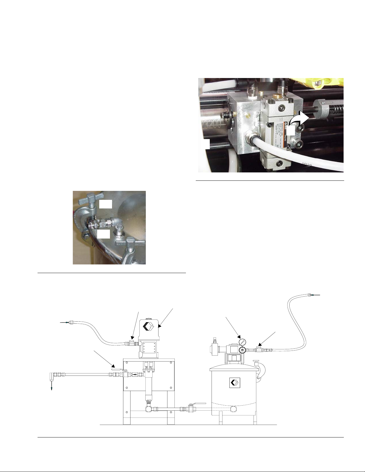
Solvent-flush Mixed Material (for units
using mix manifold gun kits)
1. Close the component A and component B valves on
the mix chamber assembly. See F
2. Ensure solvent valve is closed.
3. Set solvent flush pump air regulator to approximately 25 psi (172 kPa, 1.7 bar) and open the air
valve.
IG. 23.
8900 Proportioner with Disposable Mixer
Gun
1. Load the material. See page 19.
2. Set ratio. (For variable ratio models, see page 14).
3. Install the mixer on the gun.
4. Open the pump A and pump B air shutoff valve (S),
F
IG. 24.
S
F
FIG. 24
O
4. Open the solvent supply valve, ensuring that the dispense valve touches a grounded metal waste container and purge until solvent comes out clean.
5. Close solvent supply valve.
Component B Valve
TI3261A
Component A Valve Solvent Valve
F
IG. 23
5. Trigger the gun to dispense mixed material.
6. Adjust the component A air regulator (O) for the
desired flow rate.
7. Adjust the component B supply air regulator (F) so
that component B pressure is approximately equal
to the component A pressure.
8. When you have finished dispensing, remove and
dispose of the mixer, and install a red plastic cap
(part no. 551327).
309790ZAA 29
Page 30

Operation
Changing Component A Drum
When the ram plate is extended fully to the bottom of the
drum and the pump begins to cavitate, you need to
change the drum. It is recommended that you check and
refill the component B at the same time.
1. Close the air motor shutoff valve.
2. With the ram lever (PP) in the neutral position (F
25), adjust the ram regulator (R-F
F
IG. 25
IG. 26) to 0 psi.
3. Place the ram lever (PP) in the UP position, F
IG.
PP
IG. 26.
6. Continue to hold the drum separation air button
(PPP) just enough to keep the drum from rising with
the ram plate.
7. Follow the procedure to load material, pages 19-24.
You only need to lubricate the ram plate tire seals
the first time you load material.
R
PP
PPP
IG. 26
F
WARNING
Do not use excessive drum separation air pressure.
Make sure the drum is not damaged and the ram plate
is free to exit the drum. Read warnings, page 5.
4. Push and hold the ram separation air button (PPP).
5. Adjust the ram regulator (R) to approximately 10-15
psi (69-103 kPa, 0.7-1 bar) or until the ram plate
begins to rise.
30 309790ZAA
Page 31

Operation
Changing Component B Pail
If you are using a ram and pump to supply component
B, the procedure to change the pail is the same as
changing the Component A drum except that you use
the controls on the back of the pail ram.
Pressure Relief Procedure
(For component B tank models only.)
WARNING
PRESSURIZED EQUIPMENT HAZARD
The pressure tanks remain pressurized until pressure
is manually relieved. To reduce the risk of serious injury
from pressurized fluid or accidental spray from the gun,
always follow this procedure to relieve pressure in the
tank at the following times:
• Before you check or service any part of the spray
system
• Before you loosen or remove the pressure tank
cover or fill port.
• Whenever you stop spraying.
1. Shut off the air supply to the tank by closing the air
inlet valve. Refer to F
IG. 27.
2. Open the drain cock fitting by turning it counterclockwise.
3. Wait until there is no air escaping through the drain
cock fitting before removing the cover or opening the
fill port.
4. Leave the drain cock fitting open until you have reinstalled the cover or fill port.
FIG. 27
Air inlet valve
Fill port cap
Drain cock fitting
03089C
309790ZAA 31
Page 32

Operation
Filling Component B Pressure Tank
If you are using a pressure tank to supply component B,
check the tank level with a metal or plastic rod whenever
the Component A drum is changed. To add component
B to the tank, follow the procedure below.
1. Close the tank air supply shutoff valve, F
2. Relieve pressure in the tank (see page 27).
3. Open the fill port cap on top of cover.
CAUTION
Do not leave the pressure tank open. Component B will
crystallize if exposed to the moisture in the air.The tank
cover is normally removed only for tank cleaning.
1
Arrow points toward tank
IG. 28.
4. Gently roll an unopened pail of component B on the
floor for several revolutions to mix it.
5. Open the pail outlet and carefully pour the material
into the tank through a funnel.
6. Close the drain cock fitting and screw on the cap.
7. Make sure the silica-gel in the desiccant filter is
blue. If the gel is pink, replace it (part no. 106498) or
bake out the moisture.
The desiccant filter is an air dryer for moisturesensitive materials, it is not included with the package.
8. Pressurize the tank with dried air by opening the
component B air shutoff valve and the pressure tank
air shutoff valve.
IG. 28
F
Component B
air supply valve
1
Dry Air Line
Tank air shutoff valve
Desiccant
filter
ti3259ax
15:1 Component B pump
32 309790ZAA
Page 33

Operation
Adjust Ratio on Variable Ratio Machine
The ratio of this unit is determined partially by the difference in the area of the metering cylinders and partially
by the position of the adjustable fulcrum point in the Unibar linkage assembly. With the fulcrum in the center,
(next to stop at left of center), each meter cylinder
strokes 3 in. In this center position, the dispense ratio is
the same as the meter cylinder ratio. The ratio is adjustable from 1:1 to 20:1 depending on the location of the
fulcrum point and cylinder size. There are three
machines to accommodate these ratio ranges: 1:1-4:1,
2:1-8:1, and 5:1 to 20:1. The linkage must be adjusted
for each material application so that the combination
linkage and meter cylinder ratio equals the desired
material mix ratio by volume. The ratio is checked by
weight, but the machine meters by volume. Weight
ratios must be known before proceeding. If weight ratios
are not known, they can be calculated using the specific
gravity and known volumetric ratio of each component.
The initial linkage adjustment point can be calculated by
inserting known values into the following formula. The
resulting value is the distance in inches from the center
of the fulcrum point to the center of the component B
meter cylinder. Measure the distance from the grease
fitting on top of the fulcrum to the center of the component B cylinder meter rod. For reference, see the output
charts on pages 15 through 17.
Ratio Adjustment Calculation Example:
DR = Required mix ratio by desired volume (X:1)
PR = Selected cylinder ratio (1:1, 2:1, 5:1)
LR = Linkage ratio
LD = Linkage distance (component B cylinder center-
line to fulcrum center divided by LR+1)
DR
LR=
PR
Cylinder ratio 1:1-4:1 machine use PR = 1
Cylinder ratio 2:1-8:1 machine use PR = 2
Cylinder ratio 5:1-20:1 machine use PR = 5)
Verify the Ratio
1. Relieve pressure. See Pressure Relief Procedure
on page 27.
2. Remove gun and place a waste container under the
component A and component B hoses.
3. Open air valve to turn on unit.
4. Activate the unit and using a collection container of
known weight, collect a cup of component A and a
proportionate amount of component B.
5. Weigh each component carefully and subtract the
weight of the container.
6. Convert the manufacturer’s ratio to parts component
B per 100 parts Component A, by weight (2:1 =
100:50).
7. Divide component B weight by component A weight.
8. Multiply the result of step 7 by 100. The product is
the number of parts of component B the machine
dispenses per 100 parts of Component A.
9. Compare ratio obtained to ratio desired. Always
make several ratio checks to ensure accuracy at
final setup. Any air in the system will cause inaccurate ratio checks. If ratio checks are not consistent,
review setup procedure.
10. If the ratio is incorrect, loosen fulcrum screw (A) and
turn the ratio adjustment screw/nut (B) clockwise to
decrease and counterclockwise to increase the
amount of component B.
11. If the ratio is correct, tighten the fulcrum nut and
reattach hoses (7) to the dispensing gun.
Example:
• Desired volumetric mix ratio (DR) = 10:1
• Measured distance from grease fitting on top of the
fulcrum to the center of the component B cylinder
meter rod = 14.85 in.
DR
LR=
PR
measured distance
LD =
309790ZAA 33
10
5
LR + 1
=2:1
LD =
14.85 in.
2 + 1
or LD = 4.95 in.
Page 34

Operation
Daily Procedures
Daily Start-up Procedure
1. Perform daily maintenance operations, including:
a. Check oil level in main air lubricator.
b. Drain any water from filter in main air line.
c. Tighten pump packing nuts (daily the first week,
weekly thereafter).
d. Visually inspect system for leaks.
e. Grease zerk fittings.
2. Turn air pressure to the unit “ON”.
3. Check ratio on variable ratio models.
Steps 4 and 5 are applicable only to mix manifold
models.
4. Open the coupled ball valves (push up).
5. Ensure that the component A purge ball valve is
closed.
6. Place a material waste container under the gun outlet and open the dispense gun.
7. Dispense material until well mixed material is being
dispensed.
8. The system is now ready to operate.
After the system is purged, do not open the dispense gun until the next system operation.
Disposable Mixer System
1. Remove and discard the mixer.
2. Trigger gun to ensure the outlet is clear.
3. Turn off the main air valve.
4. Wiper off gun nose.
5. If material is moisture-sensitive or dries out, protect
the outlet with the night cap and ISO pump oil.
General Ratio Check Procedure
Checking the ratio allows the user to take samples of the
metered material to ensure the equipment is operating
properly.
The unit meters by volume but it is more convenient to check the ratio by weight. You must know
the ratio by weight or the specific gravity of the
materials to convert volumetric ratio to weight
ratio.
1. Remove the hoses from the dispense gun. Take a
material sample from the outlet of these hoses.
2. Open the air ball valves (push up) and collect a
large material sample (approximately 1 pint of component A) in separate containers of known weight.
Material flowing from each hose provides a sample
for ratio check. When sample is collected, turn off air
supply ball valve.
Daily Shut-down/Purge Procedures
Component A Purge
1. Close the coupled ball valves (push down).
2. Open the component A purge ball valve.
3. Hold the dispense gun over a material waste container.
4. Hold the dispense gun open until only component A
is evident.
5. Close the component A purge ball valve.
6. Close the main air valve located under the meter
base plate to remove air pressure from the meter.
34 309790ZAA
3. Weigh the component A and component B samples
and subtract the weight of the collection containers.
4. Convert the material manufacturer’s ratio to “parts
component B per 100 parts component A by
weight.” For example, a 2:1 ratio (component A:
component B) becomes 100:50.
5. Divide component B sample weight by component A
sample weight.
6. Multiply the result of previous step by 100. The
product is the parts component B dispensed by the
machine per 100 parts component A by weight.
7. Compare the weight ratio obtained to the desired
weight ratio. Repeat to obtain several successful
ratio checks.
8. Put new mix elements in the gun and reconnect the
hoses to the gun.
Page 35

9. Ration check is complete and the unit is ready for
operation
Ratio Check Example
Conversion Formula:
Parts by Volume (PBV) to Parts by Weight (PBW)
PBV component B
PBV component A
X
Specific gravity component B
Specific gravity component A
X = 100:Parts component B by weight
Ratio Check Example
component B sample weight LESS container weight
component A sample weight LESS container weight
PRODUCT = Parts component B per 100 parts component A
• Manufacture’s specified weight ratio = 4:1 or 100:25.
• Weight of component A in ratio check is 245 grams.
• Weight of component B in ratio check is 61.2 grams.
• 61.2 divided by 245 equals .2497 (61.2 / 245 = .2497).
X
X 100 = PRODUCT
100 =
Operation
X
Three ratio checks are recommended to ensure accuracy at final setup. The presence of any air (visible or not visible) in the material or system will cause inaccurate ratio checks. If the ratio check cannot be made with repetitive
accuracy, review air bleed procedures.
Some materials contain substantial amounts of entrained air due to manufacturing, transportation, system
setup, or drum change. Air must be removed by de-gassing, recirculation, or self removal over time, before
accurate metering can be accomplished.
309790ZAA 35
Page 36

Troubleshooting
Troubleshooting
8900 Proportioner Operating Pressures
There are four fluid pressure gauges on a typical 8900
Proportioner system. They are mounted on:
• Component A inlet block
• Component B inlet block
• Component A outlet block
• Component B outlet block
What the fluid gauges tell you
Inlet Gauge
The pump A and pump B inlet pressure gauge shows
whether there is sufficient material supply to reliably
feed each metering pump during its intake stroke.These
double- acting pumps dispense and load fluid on both
strokes.
The pump A and pump B supply air pressure should be
set high enough to maintain reliable pump feed pressures but no higher than necessary. If gauge pressure is
not consistently steady, increase fluid pressure.
The difference in the gauge reading between the
stall condition and running is the amount of dynamic
friction loss from the pump assembly, plus the
flow-induced pressure drop from the pump lower to
the pressure gauge.
Viscosity, temperature, flow rate, and gun setup can
affect the amount of gauge drop when the trigger is
pulled. On a typical manual gun system, the gauge
drops 100-400 psi (0.7-2.8 MPa, 7-28 bar).
Component B Pump Outlet Gauge
The component B pump gauge shows line pressure, but
the component B outlet pressure is generated primarily
as a reaction to component A pressure at the mix chamber.
For materials running at greater than 1:1 ratio, component B cannot open the check (injector) valve until its
pressure equals the component A pressure at the check
valve. Hoses and injector restriction are chosen to naturally balance the pressure drop while running and match
the component B pressure in the line when stalled.
Changeovers
Outlet Gauge
The pump A and pump B outlet gauge displays one of
two conditions, stalled and running.
• Stalled: With the pump air valve on and the gun
closed, the gauge will show full stall pressure. This
pressure is the fluid to air pressure ratio of the pump
assembly, times the air pressure from the main regulator, minus the friction loss of the motor and pump
assembly.
The fluid to air pressure ratio changes with different
motors, different supply pumps, and different ratio
settings.
• Running: When running, the gauge reads the
flow-induced pressure drop between the gauge and
the gun outlet. The motor power is used up by the
time the fluid exits the gun. The pressure drop is a
measure of friction loss caused by hoses, the 8900
Proportioner, fittings, mixers, and gun.
When the pumps change direction there is a momentary
change in gauges. In general, the gauges will drop
5-15%, then return. However, many factors affect the
actual fluctuation, such as pump selection, fluid characteristics, flow rate, temperature, and length of hoses.
Check valves near the pump outlets isolate the hoses to
let them serve as momentary surge chambers. This is
why flow from the gun is smooth during changeover.
Abnormal Readings
Since so many factors affect gauge readings, it is important to know what is normal. Note how your gauges read
when the machine is setup and running a good mix with
no soft spots. What are the stall pressures and what are
the running pressures for a given inbound air pressure?
How much drop is there on changeover?
If something goes wrong, a change on the gauges can
indicate what the problem is. Note those changes and
work through the troubleshooting guide, beginning on
page 39.
36 309790ZAA
Page 37

Air Supply Troubleshooting Chart
Problem Cause Solution
Troubleshooting
Abnormal pressure loss on air motor
pressure regulator gauge during both
changeovers.
Abnormal A and B pump outlet pressure loss during both changeovers.
Reduced flow rate. Undersized air compressor. Replace with properly sized air comOff-ratio material.
During normal operating conditions, the feed pump (A
and B) air motors are filled with air almost instantaneously on both changeovers.
However, if the feed pump air supply is restricted, it can
take significantly longer for air to fill the air motor. To
check for this, observe the gauge on the air motor pressure regulator during both changeovers:
• At the end of each stroke the air pressure will drop
abnormally as the air motor begins to fill.
• At the same time the A and B pump outlet pressures
will drop abnormally due to the feed pump’s respective air motor’s reduced pressure.
Air line restriction due to quick-disconnect pin fitting.
Air supply line ID to each feed pump
is too small.
Remove quick-disconnect from the
air line and replace it with bleed-type
air shutoff valve.
Replace with minimum 3/4 in. (19
mm) ID hose.
pressor.
• The decrease in the pump outlet pressures causes
the flow rate at the dispense gun to be reduced.
• Once the air motor has filled with air, all air pressures and flow rates will return to normal until the
end of the next stroke.
• The decreased pump outlet pressure may affect the
feed pumps’ checking action, and thus mix ratio,
resulting in the dispense of what appears to be
poorly mixed material.
• Changing air pressure changes the compression of
the component A hose and material. This causes an
off ratio condition until pressures stabilize. Equipment air supply pressure must always stay above
the motor regulator setpoint.
309790ZAA 37
Page 38

Troubleshooting
Pump Troubleshooting Overview
Pump Cavitation
Under normal operation, when the feed pump pressures
are balanced, component A and component B outlet
pressures are consistent.
Some up or down adjustments in feed pressures will be
necessary to keep the pumps’ outlet pressures balanced. This is due to viscosity differences in the two
materials, volumetric ratio, and required flow rate.
Because of the viscosity difference between the two
materials, most of the balancing effect comes from
adjusting the component A pressure. For ratios higher
than 1:1, the component B pressure should be set only
as high as necessary to avoid cavitation at the desired
flow rate. For 1:1 ratio there is equal balancing from
component A and component B pressure.
If either the A or B pump does not completely fill with
material on intake, the failing pump’s material output is
interrupted at the beginning of the next stroke. This is
referred to as cavitation.
Pump Failure to Seal
Under normal operation, the output of the component A
and component B pumps depends upon proper sealing
of their internal packings.
If packings fail to seal properly, the pump material output, and thus the output pressure, is reduced. Depending on the location of the failure, the pressure reduction
may occur on the pump upstroke, downstroke, or both
strokes.
Component B Pressure Relief Valve
The proportioner includes a spring-loaded, overpressure relief valve, which bypasses component B back to
the supply when pressures exceed 3400 psi (23 MPa,
234 bar).
Pump A cavitation is detected by observing the inlet
pressure gauges on pump A and pump B immediately
after changeover. When cavitation occurs, the proportioner pump outlet pressure gauge drops and the pump
A outlet pressure gauge shows an increase in pressure,
as described previously.
B pump cavitation is detected by observing the B pump
inlet pressure gauge immediately after pump top
changeover. When cavitation occurs, the B pump outlet
pressure gauge drops.
If the amount of cavitation is moderate, the pressure
gauges return to their normal readings at some point
during the downstroke of the failing pump.
During pump A cavitation, the pressure drop may cause
a noticeable reduction in flow rate at the dispense gun.
Additionally, the interruption in the pump A material output may cause component B-rich material to dispense,
which may appear as poorly mixed material.
During B pump cavitation, the interruption in the B pump
material output may cause component A- rich material
to dispense, which may appear as poorly mixed material.
38 309790ZAA
Page 39

Troubleshooting
Troubleshooting Guide: Feed pumps
Problem Cause Solution
Erratic feed pump speed. Pump cavitation. Bleed air from pump.
Pumping too fast. Turn down air pressure regulator.
Improper pump loading. Increase ram down pressure
Ram valve not in down position.
Pump lower not performing. Rebuild pump
Material leaking from top of pump Loose packing nut. Retighten.
Worn throat seals. Rebuild pump, replace seals.
Feed pump fails to cycle Air supply off. Check air valves/line pressure. Turn
on if required.
Air pressure too low. Increase air pressure on respective
feed pump air regulator.
Stalled air motor. Motor icing (warm up).
Check air filter and lubrication.
Ram fails to move up and down Lack of air pressure. Turn on or increase air supply pres-
sure to ram.
Ram failure. Check and rebuild.
Material leaking past follower plate
seal (small amount of leakage is normal)
Too much ram pressure. Reduce ram down pressure on ram
air pressure.
Worn wiper seals. Replace.
Dented container. Straighten or replace container.
309790ZAA 39
Page 40

Troubleshooting
Troubleshooting Guide: 8900 Proportioner
Problem Cause Solution
Inconsistent material mix Material inlet pressures are not set
correctly. Erratic feed pump.
Mix elements not assembled cor-
rectly or need to be replaced.
Cylinder cups are bypassing mate-
rial.
Material outlet hoses are not sized
correctly (pressures not balanced).
Material ball valves are bypassing. Rebuild/replace.
Insufficient air supply to material sup-
ply pumps.
Purge valve open (if applicable). Close during operation.
Meter pressures never change Broken material gauge(s). Replace.
Meter will not shift at the end of the
stroke.
Meter will not move Material inlet pressure not high
Material leaking from meter end caps Worn seals. Replace.
Meters not balanced Improper operation of supply pumps. Check for proper operation of mate-
Meter outlet pressure too high,
metering inaccurate, decreased flow
rate, non-uniform mix (streaking)
Incorrect ratio check and reduced
flow rate
Inaccurate metering Air in the material or trapped in the
Limit valve not working correctly. Rebuild/replace, see page 45.
No material inlet pressure. Verify.
No air supply to limit valve. Verify.
enough to drive meter.
4-way ball valve orientation incorrect. Check, fix.
Dispense valve closed. Open.
Blockage in material hose. Depressurize system and repair.
Blockage in meter assembly. Depressurize system and repair.
End caps loose. Hand tighten with wrench provided.
Inadequate material supply to
pumps.
Curing material in the mixer or block-
age of either mixer inlet port (check
valves/injector valves plugged).
Material may be bypassing rather
than flowing through the meter.
pumping and metering components.
Follow flow rate procedures and ram
feed pump troubleshooting guide.
Fix or replace.
Replace cylinder cups.
Call Graco Tech Service (800) 543-0339
Verify consistent air supply.
Verify low pressure on the gauges
before increasing.
rial supply pumps. Each should have
adequate material supply. Reasonably constant and balanced meter
inlet and outlet pressures indicate
proper pump function. If flow rate is
increased by increasing A pump
pressure, increase B pump pressure
proportionally to balance meter inlet
and outlet pressures.
Clear blockage.
Check for leakage in meter seals and
cups.
Bleed the air from the pump.
40 309790ZAA
Page 41

Troubleshooting
Troubleshooting Guide: Manifold/Mixer
Problem Cause Solution
Poor mix quality. Dirty mixer. Disassemble Tri-Core mixer, clean
housing and end caps, and replace
mix elements.
Inadequate mixing. Add mixer with more elements or
larger ID mixer.
Dirty mixer and gun. Replace flex mixer or clean Tri-Core
mixer and gun.
Tri-core mixer assembled improperly. Reassemble with scribe lines on end
caps aligned.
Fouled or plugged component B
injector.
Cavitation due to ram air control
valve not in DOWN position.
Cavitation due to low ram pressure. Increase to required operating
Reduced flow rate. Dirty mixer. Disassemble Tri-Core mixer, clean
Dirty mixer and gun. Replace flex mixer or clean Tri-core
Leaking component B shutoff valve. Repair or replace valve.
Poor purge quality. Leaking component B shutoff valve. Repair or replace valve. May require
Abnormally high B pump outlet pressures.
Abnormally high pump A outlet pressures.
Soft spots or color change relating to
changeovers.
Fouled or plugged component B
injector.
Feed pressure too high. Reduce feed pressure.
Restriction in gun or hose, plugged
check valve.
Pressures are out of balance. Adjust pressure settings on A and B
Clean or replace injector.
Place control valve in DOWN position.
pressure.
housing and end caps, and replace
mix elements.
mixer and gun.
solvent flush after valve replacement.
Clean or replace injector.
Clean out gun.
Inspect for cured material in check
valve.
supply pumps to balance outbound
ram pressure too low on feed pump.
309790ZAA 41
Page 42

Troubleshooting
Component B Injector
In most dispense systems, an injector is included in the
component B fluid line. This injector adds back pressure
to the system and provides the necessary pressure balance between component A and component B to
achieve the proper ratio and mix.
If the injector becomes fouled with mixed material, the
pressure indicated on the B pump outlet gauge will
increase and upset the pressure balance, resulting in
the dispense of poorly mixed material.
If the injector becomes completely plugged, only component A is dispensed from the gun and the B pump outlet
pressure will increase until the relief valve discharges.
If the injector valve sticks, it can react sluggishly causing
soft spots after valve triggering or changeover.
Keep the injector clean. Inspect the housing tip and needle end for dents or scratches. Lapping the needle to the
housing with automotive lapping compound will recondition the seat/needle. When reassembling the injector,
tighten the nut 2-2.5 turns after the slack is taken up.
It is good practice to have a clean injector on hand. A
fouled injector can then be replaced quickly, and thoroughly cleaned and held for future use.
Preventive Maintenance
1. Air supply: Oil level in main air line lubricator should
be checked daily and refilled when necessary with
SAE 10W non-detergent oil. Adjust to dispense 1
drop per minute during operation.
Main air line filter should be drained as required.
Excessive amounts of water in the system will
reduce machine performance.
2. Housekeeping: Spilled materials on any part of the
equipment should be cleaned up promptly. Your system is precision equipment and should be maintained as such. A light coating of petroleum jelly on
components will often prevent spilled material from
sticking to equipment.
3. Pumps: Pump packing should be tightened daily the
first week of operation and weekly thereafter.
4. When using Throat Seal Lubricant (TSL) or ISO oil,
the lubricant should be maintained at an adequate
level in the pump packing reservoir. These lubricants prevent material from sticking to pump rods,
extends packing life, and protects material from contamination from the atmosphere.
Use ISO oil when dispensing moisture-sensitive
materials.
Meter: Maintain TSL or ISO oil in reservoir if used;
grease zerk fitting. Clean up spills as soon as possible to prevent damage to the meter.
5. Mixer: With most materials, frequent use of equipment is all that is needed to prevent internal curing.
Some materials have a tendency to cure slowly on
the walls of the mixing chamber. Experience will dictate how often the mixer or mixer elements should
be thoroughly cleaned or replaced.
6. O-rings/Seals: O-rings and seals will be damaged if
soaked in solvents. When reusing, wipe with solvent
and dry immediately.
42 309790ZAA
Page 43

Service and Repair
Service and Repair
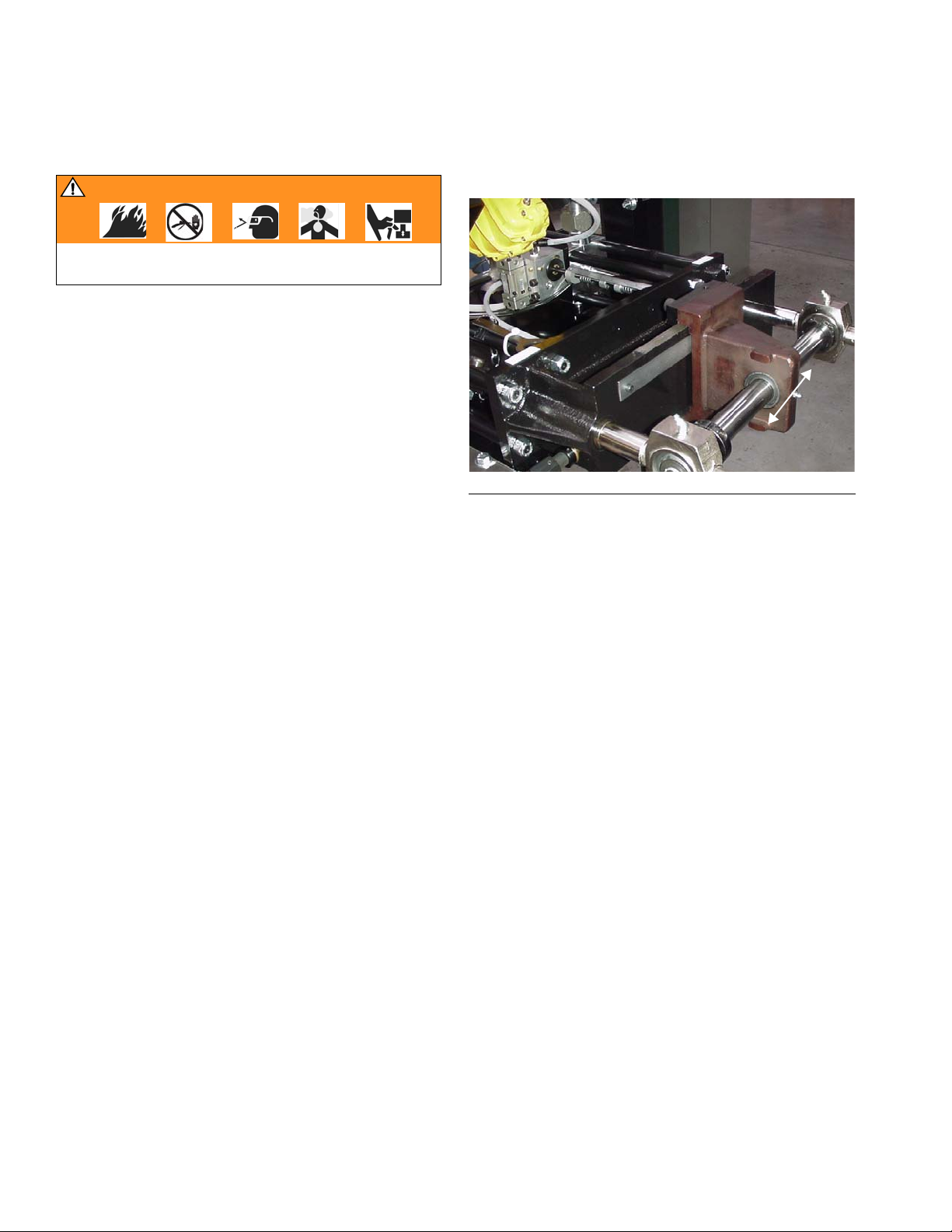
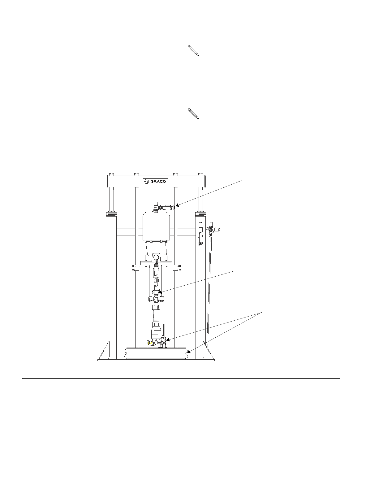
Repair the Cylinder (Fixed Ratio)
• Relieve pressure throughout the 8900 Proportioner assembly. Follow the pressure relief
procedure on page 31.
• Reference numbers shown in parentheses in
Service and Repair procedures refer to references in figures and parts lists.
17
30
116
30
113
F
IG. 29: Fixed Ratio 8900
1. Disconnect hose (17) on cylinder end manifold, FIG.
29.
2. Remove guard tube (116).
10, 11
8. Remove packing nut (103) from opposite cylinder
end cap (106) and remove throat packings and
glands (110, 111, 112).
9. Remove piston assembly (106, 107) from rods (101,
102).
10. Replace V packings and glands on both ends with
new ones and reassemble in reverse order of disassembly.
11. Replace cylinder end o-rings (109) on each cylinder
end cap. Apply grease to each to help hold o-ring
into end cap.
12. Push piston assembly through cylinder block (113).
Use grease generously during reassembly.
13. Replace o-rings (114) on each packing nut and
screw, then screw packing nut back into cylinder
end caps. Hand tighten until firmly seated on packings, then wrench tighten 1/4 turn.
14. Push cylinder assembly back together.
15. Complete reassembly of the cylinder in reverse
order of disassembly.
Use threadlocker (118) when reassembling rods
(101, 102). Torque to 55 ft-lbs (74.25 N•m).
3. Loosen and remove 4 locknuts (30).
4. Loosen nut (10) on coupling (11) and disconnect
pump rod from coupling.
If the entire cylinder needs to be removed and serviced at another location, loosen and remove
screws (49). Then loosen union (9) to remove the
cylinder assembly from unit. See page 49.
5. Pull on cylinder block (113), F
come apart.
6. Remove rod and piston assembly from cylinder.
7. Remove packing nut (115) from cylinder block (113)
and remove throat packings and glands (110, 111,
112).
309790ZAA 43
IG. 31. Cylinder should
F
IG. 30: Variable Ratio 8900
Page 44

Service and Repair
17
17
30
10
5
9
11
TI2761A
104
112
110
109
111
114
102103
106107
113
115
101
116
246558
FIG. 31
44 309790ZAA
Page 45

Service and Repair
Replace Air Valve
F
IG. 32
304 305303
1. Unscrew 2 socket head cap screws (311), FIG. 33.
2. Pull complete air valve assembly off cylinder and
connecting rod assembly.
3. Remove retaining ring and plate off end and pull rod
through.
4. Remove retaining ring off appropriate air valve
(303), pull out valve (304) and replace with new
valve.
5. Reassemble in reverse order of disassembly. Make
sure not to remove spacer (305) during disassembly. This spacer sets correct alignment of valves.
6. Reattach air valve assembly to the 8900 cylinder
block and connecting rod assembly.
311
FIG. 33
309790ZAA 45
Page 46

Disassemble Fluid Valve
Disassemble Fluid Valve
F
IG. 34
1. Relieve pressure and turn off feed supply units.
Close air valve.
4. Pull off end cap (413).
5. Pull out ball passage (411) with backup ring (409),
packing o-ring (410), and bushing (408).
6. Remove packing assemblies consisting of seal
(402), o-ring (403), bushing (404), o-rings (406,
407), and connector (405).
7. 4-way valve must be installed so that flow paths
marked on shaft (see illustration below) are 90° out
of phase with each other. Stamped indicators on
shaft end of valves show material flow paths.The
8900 Proportioner will not cycle if the valves are not
in proper phase with each other.
2. Remove valve assembly from 8900 cylinder. Take
off hose (17), union (9), fitting in (5), fitting out (5).
See F
IG. 31.
3. Remove 4 socket head cap screws (415, F
Enlarged detail of
flow path marking
IG. 35.
When reassembling, apply grease to all o-rings and
bearings.
403
402
408
409
410
411
407
405
406
404
415
IG. 35
F
46 309790ZAA
413
Page 47

Disassemble Fluid Valve
309790ZAA 47
Page 48

Parts
Parts
8900 Proportioner, Fixed Ratio
Item 7 Item 14
Part Number
570367
570369
570366
246558
Fixed
Ratio
Assembly
No.
Quantity
C24145
1:1 570371 2
1:1 24C972 2
2:1 570372 1 1
2.5:1 570373 1 1
4:1 570374 1 1
5:1 570375 1 1
9:1 246557 1 1
10:1 570376 1 1
Ref.
No. Part No. Description Qty.
1 C24016 ARM, trip 1
3 187877 TUBE, gauge 2
4 102814 GAUGE, fluid pressure 4
5 624545 T-FITTING; 3/4 npt(m) x 1/4 npt(f) 4
6 157785 UNION, swivel; 3/4 nps x 3/4 npt 4
7 CYLINDER; see table above; see
page 52
8 C19411 CONNECTOR; 3/8 npt x 3/8 tube 1
9 C24042 UNION; includes 9a 2
9a* 105802 • O-RING; fluoroelastomer 2
10 110343 SCREW; 1/2-13 UNC x 1.75 in. 1
11 C23016 COUPLING 1
12 C24013 SPACER 4
13 C24053 COUPLING 1
14 CYLINDER; see table above; see
page 52
15 16E304 COUPLING 1
17 552272 HOSE; 3/4 npt, 4000 psi (28 MPa,
276 bar)
19 100214 LOCKWASHER 4
20 C19829 SCREW; 5/16-18 x 2.5 in. 4
21 111303 NUT; hex 4
22 C24052 BRACKET, valve mounting 2
23 109212 SCREW; 3/8-24 x 3/4 in. 8
24 16E287 ACTUATOR, pneumatic 1
25 C24029 VALVE, 4-way 2
26 C24014 VALVE, limit 1
27 120753 ELBOW, 90°; 1/4 npt x 3/8 in. tube 1
570367
570366
Ref.
No. Part No. Description Qty.
28 590385 TUBE, nylon; 0.375 OD; 6 ft *
30 101926 LOCKNUT; 1/2-20 NF 8
31 C29034 WRENCH, spanner 1
32 156172 FITTING, swivel; 3/4 nps x 3/4 npt 3
38 C03190 RING 2
39 C23269 CHAIN 1
40 C24140 MANIFOLD, lube 1
41 949666 AIR CONTROL; see page 53 1
42 C30021 U-BOLT; 3/8-16 UNC 2
43 237112 VALVE, relief 1
44 113344 UNION, swivel; 1/2-14 npt x 3/4
npsm
45 113187 CONNECTOR, tube, 1/2 OD x
1/2 npt
47 061134 HOSE, nylon; 1/2 in. OD, 1.4 MPa,
(14 bar, 200 psi), 6’
48 105209 SCREW; 10-32 UNF x 7/8 in. 2
49 100101 SCREW; 3/8-16 UNC x 1 in. 10
50 100131 NUT; 3/8-16 UNC 6
51 100133 WASHER, lock; 7/16 in. 6
52 965785 BASE 1
57 100840 ELBOW; 1/4-18 npt 1
*EPDM replacement part available in kit 289401.
4
32
1
42
3
5
6
2
26
42
52
1
2
1
1
4
44
5
TI2763A
48 309790ZAA
Page 49

Parts
13
17
57
45, 46, 47
30
2
41
49
43, 44
22
23, 24
22
17
25
19, 20, 21
9
9
7
14
12
TI2761A
10
11
27
28
27
28
8
26
27
49, 50, 51
TI2762
27
40, 48
28
309790ZAA 49
Page 50

Parts
8900 Proportioner, Variable Ratio
Item 1 Item 2
Part Number
570367
570369
570366
570369
Variable
Ratio
1:1 - 4:1 570377 2
2:1 - 8:1 570378 1 1
5:1 - 20:1 570380 1 1
Ref.
No. Part No. Description Qty.
1 CYLINDER; see table above and
2 CYLINDER; see table above and
4 624545 FITTING, TEE 3/4m run X 1/4f 4
6 157785 FITTING, union, swivel 4
7 102814 GAUGE, pressure, fluid 4
8 156172 FITTING, union, swivel 5
9 552272 HOSE, PTFE 3/4-18” 5000 psi npt(m) 2
12 C23016 COUPLING, pair 2
13 C19854 SCREW, cap, socket head 2
14 C24016 ARM, trip 1
15 C24422 ROD, tie 8
16 101926 NUT, locking, metallic 16
17 C23280 8841-4-A, beam assembly 1
18 C24420 SCREW, ratio adjusting 1
19 C24419 PLUNGER 2
20 C29031 BAR, uni 1
21 C29023 ASSEMBLY, fulcrum 1
22 C29037 STOP, unibar 2
23 C19852 SCREW, cap, socket head 2
24 16E287 ACTUATOR, pneumatic 1
25 16E324 COUPLER, long 1
26 C24418 BRACKET, 3/4 valve mounting 2
27 C24029 VALVE, 4-way 2
29 109212 SCREW, cap, socket head 8
30 C19829 SCREW, cap, socket head 4
31 111303 NUT, hex 4
32 100214 WASHER, lock 4
33 C23276 MONITOR, scale 1
34 C19798 SCREW, cap, socket head 2
35 100018 WASHER, lock, spring 3
36 100321 NUT 1
38 C24014 VALVE, limit 1
39* C24042 FITTING, union, assembly 2
40 C24417 STUD 2
41 16E321 COUPLER, 3/4 in. sq x 5/8 in. sq 1
43 100847 FITTING, lubrication 2
44 C24442 PLATE, designation 1
45 C29034 TOOL, spanner wrench 1
Assembly
No.
page 52
page 52
Quantity
570366
Ref.
No. Part No. Description Qty.
46 C23269 CHAIN 1
47 C03190 RING 2
49 100840 ELBOW, street 4
53 C29043 BUSHING, ball 2
54 160327 FITTING, union, adapter, 90 degree 2
55 157191 FITTING, adapter 1
56 237112 VALVE, relief 1
57 156022 ADAPTER 1
58 205439 COUPLING, hose 1
59 061134 HOSE, nylon 6
60 C24140 MANIFOLD, lubrication 1
61 105209 SCREW, cap, socket head 2
62 949666 AIR CONTROL; see page 53 1
63 100004 SCREW, cap, hex head 8
64 100131 NUT, full hex 6
65 100133 WASHER, lock 6
66 965785 BASE, weld mount 8900 VR 1
67 C30021 BOLT, u 2
68 626814 SPACER, .75 od x .45 id x .50 lg alum 8
72 120753 FITTING, elbow, male, 90 degree 2
73 590385 TUBE, 3/8 in. OD nylon 3.6 ft *
74 120389 FITTING, tube 2
75 513754 COLLAR, shaft 1.250 cs split 2
79 113344 UNION, swivel 1
*EPDM replacement part available in kit 289401.
67
66
72, 73, 74
60, 61
62, 63, 64, 65
Top V ie w
50 309790ZAA
Page 51

75
Parts
14
30, 31, 32
43
53, 19
44
27
7, 49
54
12
13
33, 34
4
20
24, 25, 29, 25
38
21
12, 35, 36
26
75
22
23, 35
18
17
15
13
27
54
16
6
7
4
39
40
9
1
570378 and 570380 2
6
55
56
55
570377 1
54
16
9
57
58
59
309790ZAA 51
Page 52

Parts
Cylinder Assemblies
(ref. nos. 7 and 14 FR, 1 and 2 VR)
Part No. 246558
Model 246557 only
Part No. 570366
Models 570373 and 570374 only
Part No. 570367
Models 570372, 570375, and 570377 only
Part No. 570369
Models 570371 and 570376 only
Part No. C24145
Models 570371,570372, 570374, 246557,and 570376
Ref.
No. Part No. Description Qty.
101 C24054 SHAFT, piston, outer 1
102 C24055 SHAFT, piston, inner 1
103 C24022 NUT, packing 1
104 C24026 BLOCK, cylinder, inside 1
105 15C180 CYLINDER, 111; 246558 only 1
C23171 CYLINDER, 250; 570366 only
C23200 CYLINDER, 500; 570367 only
C23137 CYLINDER, 100; 570369 only
C23136 CYLINDER; 1000; C24145 only
Ref.
No. Part No. Description Qty.
106 15C181 SPACER; 246558 only 1
C23431 SPACER, 570366 only
C23460 SPACER, 570367 only
C23398 SPACER; 570369 only
C05031 SPACER; C24145 only
107 15C182 PACKING, cup; 246558 only 2
C23318 PACKING, cup; 570366 only
C23350 PACKING, cup; 570367 only
C23282 PACKING, cup; 570369 only
C05032 PACKING, cup; C24145 only
108 15C183 RING, backup; 246558 only 2
C23547 RING, backup; 570366 only
C23515 RING, backup; 570369 only
C05029 RING, backup; C24145 only
C23574 RING, backup; 570367 only
109* C20278 O-RING; fluoroelastomer 2
110 C21002 V-PACKING; PTFE 10
111 C36244 GLAND, male 2
112 C36246 GLAND, female 2
113 C24023 BLOCK, cylinder, outside 1
114* 188554 O-RING, fluoroelastomer 2
115 C57617 NUT, packing 1
116 C57618 TUBE, guard 1
117 179788 LABEL, warning 1
118 SEALANT, thread lock 1
*EPDM replacement part available in kit 289402
104 105
114
110
112
109 110111 112
111
118
102103
106107108
109
113
114
115 116 117
105
101
C24145
106107108
52 309790ZAA
Page 53

Parts
Limit Valve
(ref. no. 26 FR, 38 VR)
Part No. C24014
Ref.
No. Part No. Description Qty.
301 C20439 RING, retaining ext 4
302 C24008 WASHER 2
303 C20407 RING, retainer 2
304 C22064 VALVE 2
305 C24007 SPACER 1
306 C24051 MANIFOLD 1
307 100079 WASHER, lock, spring 2
302
301
303 304 305 306
Ref.
No. Part No. Description Qty.
308 C19977 SCREW, cap 2
309 C24012 VALVE, 4-way 1
310 C20852 FITTING, plug, 10-32 5
311 C19835 SCREW, cap socket head 2
312 C24017 ROD, trip, valve 1
313 C24009 SPRING, compression 2
314 C20068 PIN, spring 2
315 C24018 COLLAR, stop 2
316 C24019 INDICATOR, scale 1
317 C19146 SCREW, mach, slotted round head 2
318 C24020 COLLAR, clamp 1
319 C19264 PLUG, pipe plug 1/4 in. 3
320 C24016 ARM, trip 1
319 319
307
308
309
310
311
312
313
314
315
320
316
318
317
309790ZAA 53
Page 54

Parts
Air Control
(ref. no. 41 FR, 62 VR)
Part No. 949666
Ref.
No. Part No. Description Qty.
201 626086 BRACKET 1
202 624225 AIR MANIFOLD 1
203 157191 ADAPTER; 3
204 206197 AIR REGULATOR; 1/2 x 3/4 npt 2
205 100840 ELBOW; 1/4-18 npt 2
206 160430 GAUGE, air pressure 2
207 1554701 UNION, 90° swivel; 1/2-14 npsm x
1/4-14 npt
208 105170 SCREW; 1/4-20 UNC x 2 in. 3
209 100015 NUT; 1/4-20 UNC 5
210 100016 WASHER, lock 5
211 110225 VALVE, 2-way, vented; 1/2-14 npt 2
208
221
226
209
210
Ref.
No. Part No. Description Qty.
212 103475 TEE; 1/2 npt 1
213 100122 NIPPLE; 1/2-14 npt 2
214 214848 LUBRICATOR, air line 1
215 106149 FILTER, air; 1/2 npt 1
216 172124 NIPPLE; 1/2-14 x 3/8-18 npt 1
219▲ 551206 WARNING LABEL 1
220▲ 551207 INSTRUCTION LABEL 1
221 158990 AIR MANIFOLD 1
222 158491 NIPPLE; 1/2-14 npt 1
223 155495 UNION, 90° swivel; 1/4 npsm x 3/8
npt
224 162453 NIPPLE; 1/4 npsm x 1/4 npt 2
225 101748 PLUG; 3/8-18 npt 2
3
226 100361 PLUG; 1/2-14 npt 1
227 C19411 CONNECTOR; 3/8 tube x 3/8 npt 1
228 106285 U-BOLT; 1/4-20 UNC 2
229 C19394 ELBOW, 90°; 3/8 tube x 3/8 npt 1
2
225
223
229
202
227
201
223
222
203
(behind)
206
204
205
207
220
203
211
224
213
212
213
214
219
216
225
215
222
210
228
211
207
210
228
54 309790ZAA
Page 55

Parts
4-Way Valve
(ref. no. 25 FR, 27 VR)
Part No. C24029
Ref.
No. Part No. Description Qty.
401 C24030 BODY, valve 1
402 C24031 SEAL 4
403* C24036 PACKING, o-ring 4
404 C24033 BUSHING 4
405 C24034 FITTING, connector 4
406* C24035 PACKING, o-ring 4
407* C24032 PACKING, o-ring 4
Ref.
No. Part No. Description Qty.
408 C24037 BUSHING 2
409 C24038 RING, backup 4
410* 103611 PACKING, o-ring 2
411 C07068 BALL, passage 1
412* C24040 PACKING, o-ring 1
413 C24041 CAP, end 1
414 100133 WASHER, lock 4
415 C19839 SCREW, cap, socket head 4
*EPDM replacement part available in kit 289401.
401
402
403
404
405
406
407
414
415
408
409
410
409
411
409
410
409
408
412
413
405406407
309790ZAA 55
Page 56

Parts
Pump Feed Module Selection for Component A or Component B
20:1 President on 5 Gallon Ram
(See Graco Manuals 308026 and 306838)
Module No. 965571
Ref.
No. Part No. Description Qty.
4 237207 PUMP, President, 20:1 1
13 222812 PLATE, wiper, 5 gallon 1
22 102556 RIVET, blind 4
24 156823 UNION, swivel 1
27 184147 SHIELD, 5 gallon ram 1
35 113269 VALVE, ball, vented, .500 1
36 155865 UNION, adapter 1
37 237569 WIRE, assy, 25 ft 1
42 156971 NIPPLE, short 1
43 104984 TEE, pipe 1
44 113286 VALVE, safety 1
45 160701 ELBOW, street 1
47 237562 SUPPORT, pump 1
48 113208 FITTING, tube 2
49 113896 VALVE, control 1
51 104765 PLUG, pipe headless 1
52 110318 REGULATOR, air, 1/4 in.npt 1
53 110319 GAUGE, pressure, air, 1/8 in. npt 1
54 160107 NUT, cap 1
Ref.
No. Part No. Description Qty.
55 101533 WASHER, spring lock 1
56 190265 SPACER 1
57 238925 PISTON, ram, 5 gallon 1
58 166552 CAP, cylinder 1
59 206726 BASE, and cylinder 1
63 054123 TUBE, nylon 3.7 ft *
65 190256 CLAMP, support 2
66 100680 SCREW, cap, hex head 4
67 101566 NUT, lock 4
68 100023 WASHER, flat 4
70 114320 FITTING, connector, 1/8 npt(f) 1
71 115901 TRIM, edge, protection 2
72 160327 UNION, adapter, 90° 2
73 235497 VALVE, check 1
74 100896 FITTING, bushing, pipe 2
75 H45010 HOSE, fluid; nylon; 1/2 in. (13 mm)
ID; 1/2 npsm(fbe); 10 ft (3.05 m)
long
76 214656 HOSE, coupled, 61209, 10 ft 1
77 109126 HOSE coupled, 10 ft 1
79 155470 UNION, swivel, 90° 1
80 158491 FITTING, nipple 2
1
56 309790ZAA
Page 57

Parts
49
48
63
53
45
77
24
52
51
54
55
4
76, 36
35
56
67
42
5
79
80
43
44
47
57
37
68
59
72, 73, 74, 80, 75
22
66
60
48
71
65
65
13
70
06537
309790ZAA 57
Page 58

Parts
34:1 Senator on 5 Gallon Ram
(See Graco Manuals 308026 and 306838)
Module No. 965597
Ref.
No. Part No. Description Qty.
1 222769 PUMP, senator (4.5 cm) 1
2 100468 SCREW, cap, hex head 4
3 100133 WASHER, lock 4
4 222812 PLATE, wiper, 5 gallon 1
7 101154 PIN, driv-lok 1
10 102556 RIVET, blind 4
12 107144 SCREW, cap, hex head 1
15 184150 SPACER, rod, elevator 1
17 184147 SHIELD, 5 gallon ram 1
22 206726 BASE, and cylinder 1
23 101533 WASHER, spring lock 1
24 166552 CAP, cylinder 1
25 113208 FITTING, tube 2
26 113896 VALVE, control 1
29 160107 NUT, cap 1
30 054123 TUBE, nylon 3.7 ft *
34 110318 REGULATOR, air, 1/4 in. npt 1
Ref.
No. Part No. Description Qty.
35 110319 GAUGE, pressure, air, 1/8 in. npt 1
36 104765 PLUG, pipe, headless 1
37 155541 UNION, swivel, 90° 1
38 238925 PISTON, ram, 5 gal. 1
39 166533 SUPPORT, pump 1
40 110225 VALVE, ball, vented 1
45 237569 WIRE, assy, 25 in. 1
46 180916 MANIFOLD, adapter 1
47 114003 VALVE, safety 1
50 114320 FITTING, connector, 1/8 npt(f) 1
52 160327 UNION, adapter, 90° 3
53 115901 TRIM, edge, protection 2
55 235497 VALVE, check 1
56 157191 FITTING, bushing, pipe 1
57 215238 HOSE, coupled, 61220 1
58 214656 HOSE, coupled, 61209, 10 in. 1
59 109126 HOSE, coupled, 10 in. 1
60 156684 UNION, adapter, swivel 1
58 309790ZAA
Page 59

58
Parts
40
26
25
35
53
34
59
22
15
37
36
23,29
30
50
39
60
47
46
52
1
2
3
52
55
4
55
30
53
25
30
52
10
51
57
05687x
309790ZAA 59
Page 60

Parts
23:1 Monark on 5 Gallon Ram
(See Graco Manuals 308026 and 306838)
Module No. 570142
Ref.
No. Part No. Description Qty.
1 184147 SHIELD, 5 gallon ram (not shown) 1
2 206994 FLUID, TSL 8 oz bottle (not shown) 1
4 222782 PUMP, Monark 1
11 222812 PLATE, wiper, 5 gallon 1
19 156823 UNION, swivel 1
25 155470 UNION, swivel, 90° 1
27 113269 VALVE, ball, vented .500 1
28 155865 UNION, adapter 1
29 237569 WIRE, assy, 25 ft 1
34 156971 NIPPLE, short 1
35 104984 TEE, pipe 1
36 113286 VALVE, safety 1
37 160701 ELBOW, street 1
41 238925 PISTON, ram, 5 gallon 1
42 237562 SUPPORT, pump 1
43 160107 NUT, cap 1
44 101533 WASHER, spring lock 1
45 190265 SPACER 1
47 054123 TUBE, nylon 3.7 ft *
49 110319 GAUGE, pressure, air, 1/8 in. npt 1
Ref.
No. Part No. Description Qty.
50 110318 REGULATOR, air, 1/4 in. npt 1
51 104765 PLUG, pipe, headless 1
52 113896 VALVE, control 1
53 166552 CAP, cylinder 1
54 206726 BASE, and cylinder 1
55 113208 FITTING, tube 2
58 190256 CLAMP, support 2
59 100680 SCREW, cap, hex head 4
60 101566 NUT, lock 4
61 159239 FITTING, nipple, pipe, reducing 1
62 100023 WASHER, flat 4
64 114320 FITTING, connector 1/8 npt(f) 1
65 115901 TRIM, edge, protection 2
66 100896 FITTING, bushing, pipe 3
67 160327 UNION, adapter, 90° 2
68 235497 VALVE, check 1
69 H45010 HOSE, fluid; nylon; 1/2 in. (13 mm)
ID; 1/2 npsm(fbe); 10 ft (3.05 m)
long
70 214656 HOSE, coupled, 61209, 10 ft 1
71 109126 HOSE, coupled, 10 ft 1
73 158491 FITTING, nipple 2
1
60 309790ZAA
Page 61

70
Parts
55
52
47
49
37
50
71
19
47
67
47
41
53
43
51
45
34
35
36
44
69
73
66
25
42
68
28
61
60
27
4
58
62
59
29
55
54
66
67
65
48
47
11
64
05689C
309790ZAA 61
Page 62

Parts
20:1 President on 55 Gallon Ram
(See Graco Manuals 306934 and 308027)
Module No. 570114
Ref.
No. Part No. Description Qty.
1 215335 BASE, ram 1
2 222768 PUMP, President (4.5 cm) 1
3 276025 CLAMP 4
5 206537 CLAMP, drum 1
7 184140 PLATE, mounting 1
9 237569 WIRE, assy, 25 ft 1
10 104984 TEE, pipe 1
11 113286 VALVE, safety 1
12 156971 NIPPLE, short 1
16 102637 SCREW, cap 4
18 100101 SCREW, cap, hex head 4
19 100122 NIPPLE, close 1
20 100133 WASHER, lock 4
22 100672 SCREW, set 4
23 100132 WASHER, flat 4
24 100464 SCREW, lag 4
25 101533 WASHER, spring lock 4
26 101535 NUT, full hex 4
28 189559 CAP, end 2
29 160701 ELBOW, street 1
31 157416 UNION, swivel, 90° 1
32 158979 FITTING, nipple, pipe, reducing 1
36 110319 GAUGE, pressure, air, 1/8 in. npt 1
37 155541 UNION, swivel, 90° 1
38 110318 REGULATOR, air, 1/4 in. npt 1
Ref.
No. Part No. Description Qty.
40 158256 UNION, swivel 1
41 113269 VALVE, ball, vented, .500 1
45 161822 PLATE, mounting 2
46 054123 TUBE, nylon 3.6 ft *
47 111162 FITTING, elbow 1
48 167652 ROD, tie ram 2
49 238928 PISTON, 55 gallon ram 2
50 114363 VALVE, ball, fluid 1
51 167646 BEAM, ram 1
52 166552 CAP, cylinder 2
55 238929 PLATE, 55 gallon ram 1
56 109495 PACKING, o-ring 1
58 208048 HOSE, coupled 61089 1
64 100403 PLUG, pipe 1
69 113896 VALVE, control 1
75 100270 SCREW, cap, hex head 2
76 100016 WASHER, lock 2
77 114243 VALVE, check 1
78 156849 UNION, adapter, 90° 1
79 113915 FITTING, union 1
80 158212 BUSHING 1
81 235497 VALVE, check 1
82 160327 UNION, adapter 90 2
83 215238 HOSE, coupled, 61220 1
84 214651 HOSE, coupled, 61209, 17 ft 1
85 109126 HOSE, coupled, 72 in. 1
87 184037 FITTING, outlet (6 cm) 1
62 309790ZAA
Page 63

6
36
37
Parts
85
54
25,26
53
51
49
52
29
1
12
10
69
2
52
46
58
80
9
82
48
20,18
84
7
40
1
22
45
41
83
22
58
13
78
21
77
16
81
82
3
56
50
32
55
0717E
309790ZAA 63
Page 64

Parts
34:1 Senator on 55 Gallon Ram
(See Graco Manual 308027)
Module No. 965572
Ref.
No. Part No. Description Qty.
3 235497 VALVE, check 1
4 160327 UNION, adapter, 90° 2
5 215238 HOSE, coupled, 61220 1
6 214651 HOSE, coupled, 61209, 17 ft 1
7 109126 HOSE, coupled, 10 ft 1
9 222769 PUMP, Senator (4.5 cm) 1
10 241253 RAM, pneumatic, EPDM, 55 gallon 1
11 276025 CLAMP 4
12 102637 SCREW, cap 4
15 113269 VALVE, ball, vented, .500 1
Ref.
No. Part No. Description Qty.
20 109495 PACKING, o-ring 1
21 111803 SCREW, cap, hex head 4
22 100133 WASHER, lock 4
23 158979 FITTING, nipple, pipe, reducing 1
25 114363 VALVE, ball 1
30 158256 SWIVEL, union assembly 1
31 100896 FITTING, bushing, pipe 1
34 206537 CLAMP, drum 1
35 155541 UNION, swivel 1
36 158212 BUSHING 1
6
36
30
15
31
7
21
22
9
10
12
11
4
35
5
4
3
20
0717E
64 309790ZAA
Page 65

Parts
31:1 Bulldog on 55 Gallon Ram
Module No. 570141
Ref.
No. Part No. Description Qty.
2 237261 PUMP, Bulldog, 31:1 1
3 235497 VALVE, check 1
4 160327 UNION, adapter, 90° 2
5 215238 HOSE, coupled, 61220 1
6 214651 HOSE, coupled, 61209, 17 ft 1
7 109126 HOSE, coupled, 10 ft 1
8 158212 BUSHING 1
15 158555 NIPPLE, reducing 1
17 241253 RAM, pneumatic, EPDM, 55 gallon 1
Ref.
No. Part No. Description Qty.
20 C20487 FITTING, nipple, hex 1
26 113332 VALVE, ball, vented, .750 1
28 155541 UNION, swivel, 90° 1
29 276025 CLAMP 4
30 102637 SCREW, cap 4
31 109495 PACKING, o-ring 1
32 100101 SCREW, cap, hex head 4
33 100133 WASHER, lock 4
37 237569 WIRE, assy, 25 ft 1
39 100505 FITTING, bushing, pipe 1
40 158979 FITTING, nipple, pipe, reducing 1
41 114363 VALVE, ball 1
37
26
20
7
6
8
17
29
30
28
4
5
4
15
3
31
9348C
309790ZAA 65
Page 66

Parts
20:1 Senator on 55 Gallon Drum
Module No. 570309
Ref.
No. Part No. Description Qty.
1 570308 PUMP, 20:1 Senator Dura-Flo 750 1
2 207408 ELEVATOR, stationary 1
3 237579 KIT, repair 1
6 514944 VALVE, needle sst 1/2 MF 6000 1
7 159842 ADAPTER 1
8 100380 BUSHING, pipe 1
9 501764 FITTING, elbow 90°
1 in. npt(f) x 1 in. n
10 237309 COVER, drum 1
11 208536 COUPLER, line, air 1
12 158491 FITTING, needle 1
13 237578 SUPPORT, cover assy, sst 1
14 215239 HOSE, coupled 61220 1
22 160327 UNION, adapter, 90° 2
23 160032 NIPPLE 2
Ref.
No. Part No. Description Qty.
24 102644 VALVE, ball 2
25 157785 UNION, swivel 1
26 214656 HOSE, coupled 61209, 10 ft 1
28 102471 SCREW, cap hex head 3
29 102021 NUT, lock 3
31 205349 HOSE, coupled 61120, 15 ft 1
32 162449 FITTING, nipple, reducing 2
33 157785 FITTING, union, swivel 1
34 180916 FITTING, tee 3/4(m) run x 1/4(f)
branch
35 214037 VALVE, ball 3
36 109126 HOSE, coupled, 10 ft 1
1
38 187614 NUT, jam 1
39 159446 GASKET, vellumoid 1
40 15C321 PLATE, cover 1
41 100896 FITTING, bushing, pipe 1
42 15C322 RETAINER, siphon tube 1
43 190999 NUT, retainer 1
44 238161 TUBE, siphon, hd agitator 1
45 113218 VALVE, ball, vented, .750 1
1
24
23
22
33
34
14
25
35
24
23
31
22
11
26
10
41
45
1
2,3
9
12
6
7
32
8
36
44
31
43
28
29
44
Detail A
13
42
40
39
38
See Detail A
10
66 309790ZAA
Page 67

9:1 DynaMite on 1 Gallon Can Ram
Module No. 570249
3
Ref.
No. Part No. Description Qty.
1 235871 PUMP, extruder, sst, 190 1
2 217298 BRACKET, mounting 1
3 514518 HOSE, coupled 3/16 in. x 3 ft 1
4 109125 HOSE, coupled 72 in. 1
5 224908 INDUCTOR, assy, 1 gal. 1
6 156823 UNION, swivel 2
7 156971 NIPPLE, short 2
Parts
Ref.
No. Part No. Description Qty.
8 C24332 BOLT, “U” 2
9 100615 BUSHING, hex steel 1
10 101885 SCREW, cap sch 2
11 102040 NUT, lock, hex 2
12 100086 WASHER, plain 1
13 155541 UNION, swivel, 90° 1
14 100206 BUSHING, pipe 1
7
7
3
5
9
1
6
14
4
13
10,11,12
2
8
8
309790ZAA 67
Page 68

Parts
10 Gallon Press Tank with 15:1 Booster
Module No. 570037
Ref.
No. Part No. Description Qty.
2 101946 PIN, cotter, sst 1
3 102325 ELBOW, 90° 1
5 156082 PACKING, o-ring 1
6 156823 UNION, swivel 1
7 157785 UNION, swivel 2
8 217296 FRAME, pump 1
9 167682 ROD, tie 3
10 207352 MOTOR, air, pres 1
11 207370 ROD, connecting 1
12 215930 PUMP, displ, recip 1
13 221170 HOSE, coupled, 061260, 3 ft 1
14 236150 TANK, high pressure 10 gallon 1
10
30
32
33
21,22,23,24,25
2,5,11,26
Ref.
No. Part No. Description Qty.
15 236662 AGITATOR, heavy duty, 10 gallon 1
16 236677 KIT, repair 1
17 501603 VALVE, check 1/2 in. npt mbe sst tf 1
18 512484 VALVE, ball, sst 1
19 620198 PLATE, mounting 1
21 100101 SCREW, cap, hex head 4
22 100133 WASHER, lock 4
23 100131 NUT, full hex 4
24 100016 WASHER, lock 2
25 100022 SCREW, cap, hex head 2
26 150707 PLATE, designation 1
27 H45010 HOSE, fluid; nylon; 1/2 in. (13 mm)
ID; 1/2 npsm(fbe); 10 ft (3.05 m)
long
28 100896 FITTING, bushing, pipe 1
29 160327 UNION, adapter, 90° 1
30 214656 HOSE, coupled, 61209, 10 ft 1
31 109126 HOSE, coupled, 10 ft 1
32 158491 FITTING, nipple 3
33 107142 VALVE, ball, vented 1
31
15
6
9
8, 19
1
28
29
68 309790ZAA
32
27
32
18
17
12
7
14
3
13
16
Page 69

10:1 President 5 Gallon Pail Cover
Module No. 570264
Parts
Ref.
No. Part No. Description Qty.
1 903295 PUMP, 10:1 President, sst 1
3 100035 SCREW, machine, panhead 1
4 206755 CHAIN 1
5 165096 PLUG 1
25
27
25
3
4
5
6
19
13
8
23
See
Detail A
Ref.
No. Part No. Description Qty.
6 165516 PACKING, o-ring 1
7 101962 SCREW, set sch 2
8 100220 SCREW, thumb 3
21
20
1
28
30
11
29
21
22
12
14
15,16
10
9
7
Detail A
309790ZAA 69
24
Page 70

Parts
Mix Kit Selection
Cartridge Fill Medium Viscosity Wide Ratio
Module No. 570248
Ref.
No. Part No. Description Qty.
4 626748 BRACKET, mount disp valv C24342 1
5 552204 ACTUATOR, air, 8900 metered shot 1
6 C30021 BOLT, u 1
10 504327 HOSE, nylon 3/4 in. id 4
11 504621 COUPLING, hose 4
12 166590 ELBOW, street 2
13 160327 UNION, adapter, 90° 2
14 175013 NIPPLE, pipe 1
15 512442 HOSE, bulk 1/2 in. nylon 3500 psi 8
16 503917 COUPLING, hose 1/2 ft npt(m) x
1/2, 3903
17 105281 UNION, swivel, 90° 1
18 512616 HOSE, PTFE 1/4 x 18 in. 1/4 npsm 1
19 500517 FITTING, tee 3/4 in. npt 1
20 158683 FITTING, elbow 3/4 in. npt 4
24 100896 FITTING, bushing, pipe 5
25 155470 UNION, swivel, 90° 1
26 156684 UNION, adapter, 2
27 100840 ELBOW, street 2
32 156971 NIPPLE, short 4
33 626758 MANIFOLD, block 8900 meter, shot 1
34 626757 BLOCK, check 8900 metered shot 1
35 C26088 VALVE, cone extension 1
36 C26086 STOP, cone, assembly 1
37 103374 SCREW, machine, rdh 4
38 105192 SCREW, cap, hex head 1
40 C24017 ROD, trip, valve 1
41 C20068 PIN, spring 2
42 C24018 COLLAR, stop 2
43 C24020 COLLAR, clamp 1
44 120753 FITTING, elbow, male, 90° 4
45 513066 TUBE, 3/8 ft OD nylon 3
46 C12509 TUBE, nylon 20
Ref.
No. Part No. Description Qty.
47 597151 FITTING, elbow 6
48 552211 VALVE, pulse pneumatic 2
49 593538 VALVE, shuttle 1/8 npt(f) 1
50 503028 VALVE, air, push-pull 1
51 104631 KIT, accessory 1
52 100730 BUSHING 2
53 104984 TEE, pipe 2
54 C19391 FITTING, elbow 1/4 npt(m) x 1/4 od
56 512420 FITTING, cross steel 3/8 npt 1
8
57 100195 NIPPLE, pipe 1
58 103656 FITTING, pipe, hex 2
59 599433 FITTING, elbow, male 1
60 501014 ACTUATOR, air 1/8 npt(f) 2
63 114372 MIXER, static, 1/2 npt 2
64 158581 COUPLING, hex 2
65 948081 MIXER, tri-core 1/2(m) x 1/2(f) 1
66 159153 UNION, swivel 1
67 690270 ADAPTER, luer lock 1/4 in. npt 2
68 112012 NOZZLE, needle 2
69 112019 NOZZLE, needle 2
70 205324 HOSE, coupled, 61120, 1 ft 1
71 164672 ADAPTER 2
73 159239 FITTING, nipple, pipe, reducing 1
74 552208 VALVE, ball 3-way 1
75 100206 BUSHING, pipe 2
76 552205 MIXER, pipe, sst 1/4-4.2 in. 12 el 2
77 626760 MANIFOLD, ratio check 8900 shot 1
79 102646 VALVE, ball 1
80 156877 NIPPLE, long 1
81 112013 NOZZLE, needle 2
82 112014 NOZZLE, needle 2
83 112015 NOZZLE, needle 2
84 112020 NOZZLE, needle 2
85 112021 NOZZLE, needle 2
86 112022 NOZZLE, needle 2
87 162449 FITTING, nipple, reducing 2
88 100403 PLUG, pipe 2
90 158491 FITTING, nipple 1
tube
4
70 309790ZAA
Page 71

Parts
47 (2)
V1 front
V2 rear
27
76
75
74
24
87
32
65
32
31
70
18
71
64
12
17
13
12
15,16
15,16
10,11
88 (2)
14
24
19
4,37
26
V1
5
V2
80
73
7
33
24
20
87
63
64
24
25
79
34,35,36,38
68,81,82,83
90
67
34
77
67
69,84,85,86
13,24
43
44
44
45
54
46
41
45
42
59
47
52
40
56
57
51
54
46
60
52
46
See Detail C
47
46
58
50
60
49
53
32
46
47
58
47,48
44
54
Detail C
To bottom front
To bottom rear
46
309790ZAA 71
Page 72

Parts
Cartridge Fill High Viscosity Wide Ratio
Module No. 570318
Ref.
No. Part No. Description Qty.
1 552204 ACTUATOR, air, 8900 metered shot 1
2 626748 BRACKET, mount disp valv C24342 1
3 103374 SCREW, machine, rdh 4
4 100896 FITTING, bushing, pipe 1
5 156877 NIPPLE, long 1
6 105192 SCREW, cap, hex head 1
7 626757 BLOCK, check 8900 metered shot 1
8 626758 MANIFOLD, block 8900 meter shot 1
9 166590 ELBOW, street 1
10 513375 MIXER, pipe sst 3/4-16.4 in. 2 el 2
11 100349 FITTING, elbow 3
12 160032 NIPPLE 1
13 552208 VALVE, ball 3-way 1
14 100206 BUSHING, pipe 2
15 552205 MIXER, pipe sst 1/4-4.2 in. 24 el 2
16 100840 ELBOW, street 4
17 157350 ADAPTER, 3/8 npt x 1/4 npt 2
18 205324 HOSE, coupled, 61120, 1 ft 1
19 162449 FITTING, nipple, reducing 1
20 100040 PLUG, pipe 1
21 155699 ELBOW, street 1
22 159239 FITTING, nipple, pipe, reducing 1
23 102646 VAVLE, ball 1
24 158491 FITTING, nipple, 1/2 npt 1
25 C26088 VALVE, cone extension 1
26 C26086 STOP, cone assembly 1
27 151249 NIPPLE, pipe 1
28 112698 ELBOW, male, swivel 1
Ref.
No. Part No. Description Qty.
29 C12509 TUBE, nylon 30
30 503028 VALVE, air, push-pull 1
31 157191 FITTING, adapter 4
32 596832 FITTING, tee, tube 1
33 501014 ACTUATOR, air 1/8 npt(f) 2
34 103656 FITTING, pipe, hex 1
35 593538 VALVE, shuttle 1/8 npt(f) 1
36 552211 VALVE, pulse, pneumatic 2
37 C19391 FITTING, elbow 1/4 npt(m) x 1/4 od
tube
38 104631 VALVE. foot 1
40 626760 MANIFOLD, ratio check 8900 shot 1
42 H55033 HOSE, bulk 1/2 in. nylon 5600 psi 6
47 100133 WASHER, lock 2
48 100131 NUT, full hex 2
50 104172 FITTING, tube 2
51 512231 CONNECTOR, 1/4 od x 1/8 in.
npt(f)
54 156971 NIPPLE, short 5
55 233415 KIT, accessory, ratio check 1
58 157785 UNION, swivel 1
60 160327 UNION, adapter, 90° 2
61 166466 TEE, pipe, female 1
63 104984 TEE, pipe 2
64 120753 FITTING, elbow, male, 90° 2
65 100003 SCREW, cap, hex head 2
66 100176 BUSHING, hex 1
68 512616 HOSE, coupled 61120, 1.5 ft 1
69 100615 BUSHING, hex 1
5
2
72 309790ZAA
Page 73

Parts
4
61
58
60
64
63
54
Detail C
42
37
24 23
22
69
61
See Detail C
65
42
17
18
11
31
10
11
12
See Detail A
42
68
See Detail C
59
58
2,3
2, 3
1
42
31
6
4
5
7
21
26
20
8
16
15
25
66
29
37
37
51
36
33
35
36
51
32
34
30
27
29
29
33
50
1
38
37
29
29
50
28
6
1
40
54
55
This view rotated 90° for clarity
1918141391416 15
Detail A
309790ZAA 73
Page 74

Parts
Brush Grade High Viscosity Wide Ratio
Module No. 570358
Ref.
No. Part No. Description Qty.
1 159841 ADAPTER 3
2 114112 FITTING, connector, female 1
3 100030 BUSHING 1
4 626748 BRACKET, mount disp valv C24342 1
5 552204 ACTUATOR, air 8900 metered shot 1
6 C30021 BOLT, u 2
7 155699 ELBOW, street 1
8 100615 BUSHING, hex steel 1
9 159801 UNION, swivel, 90° 1
10 504327 HOSE, nylon 3/4 in. id 4
11 504621 COUPLING, hose 4
12 166590 ELBOW, street 2
13 160327 UNION, 2
14 175013 NIPPLE, pipe 1
15 512442 HOSE, bulk 1/2 in. nylon 3500 psi 8
16 503917 COUPLINE, hose, 1/2 npt(m) x 1/2,
3903
17 105281 UNION, swivel 45° 1
18 512616 HOSE, PTFE 1/4 x 18 ft 1/4 npsm 1
19 500517 FITTING, tee 3/4 in. npt 1
20 158683 FITTING, elbow, 90° 5
24 100896 FITTING, bushing, pipe 5
25 155470 UNION, swivel, 90° 1
26 156684 UNION, adapter 2
27 100840 ELBOW, street 4
31 512912 MUFFLER, polyethylene 1/2 npt 2
32 156971 NIPPLE, short 5
33 626758 MANIFOLD, block 8900 meter shot 1
34 626757 BLOCK, check 8900 metered shot 1
35 C26088 VALVE, cone extension 1
36 C26086 STOP, cone, assembly 1
37 133374 SCREW, machine, rdh 4
38 105192 SCREW, cap, hex head 1
40 C24017 ROD, trip, valve 1
41 C20068 PIN, spring 2
42 C24018 COLLAR, stop 2
43 C24020 COLLAR, clamp 1
44 120753 FITTING, elbow, male, 90° 6
45 513066 TUBE, 3/8 in. OD nylon 6
46 C12509 TUBE, nylon 20
47 597151 FITTING, elbow 11
48 552211 VALVE, pulse pneumatic 2
49 593538 VALVE, shuttle 1/8 npt(f) 2
50 503028 VALVE, air, push-pull 1
51 212099 KIT, accessory 1
52 100730 BUSHING 2
53 104984 TEE, pipe 2
54 C19391 FITTING, elbow 1/4 npt(m) x 1/4 od
tube
56 512420 FITTING, cross steel 3/8 npt(f) 1
57 100195 NIPPLE, pipe 1
Ref.
No. Part No. Description Qty.
58 103656 FITTING, pipe, hex 4
59 599433 FITTING, elbow, male 1
60 501014 ACTUATOR, air 1/8 npt(f) 3
63 114372 MIXER, static, 1/2 npt 2
54 158581 COUPLING, hex 2
65 948081 MIXER, tri-core 1/2(m) x 1/2(f) 1
66 159153 UNION, swivel 1
67 690270 ADAPTER, luer lock 1/4 in. npt 2
68 112012 NOZZLE, needle 2
69 112019 NOZZLE, needle 2
70 205324 HOSE, coupled, 61120, 1 ft 1
71 164672 ADAPTER 2
72 162449 FITTING, nipple, reducing 1
73 159239 FITTING, nipple, pipe, reducing 1
74 552208 VALVE, ball, 3-way 1
75 100206 BUSHING, pipe 3
76 552205 MIXER, pipe sst 1/4-4.2 in. 12 el 2
77 626760 MANIFOLD, ratio check 8900 shot 1
79 102646 VALVE, ball 1
80 156877 NIPPLE, long 1
82 100175 COUPLING, pipe 2
83 511351 MIXER, static 2
84 108233 VALVE, needle 1
8
85 156823 UNION, swivel 1
86 965766 VALVE, 1k-ul, machine mount 1
90 101353 NIPPLE, pipe 1
91 157416 UNION, swivel, 90° 1
92 158491 FITTING, nipple 1
93 501459 VALVE, toggle, air 1
94 110460 FITTING, el male swivel,
95 598140 FITTING, elbow 5/32t x 1/8 in.
96 510220 VALVE, air 4-way spring 1/4 npt 1
97 104165 FITTING, tube 2
98 164815 FITTING, adapter, tee 1
99 503279 FITTING, union straight 1/8 in. mxf sw1
100 112013 NOZZLE, needle 1
101 112014 NOZZLE, needle 2
102 112015 NOZZLE, needle 2
103 112020 NOZZLE, needle 2
104 112021 NOZZLE, needle 2
105 112022 NOZZLE, needle 2
5
10-32x5/32
npt(m)
1
1
74 309790ZAA
Page 75

Parts
27
82
32
84
47
85
86
82
27
83
63
9
8
7
75
32
31
70
64
18
71
12
20
17
65
13
12
24
15,16
10,11
5
33
4,37
26
91
90
92
7, 73
25
79
34,35,36,38
24
67
68
15,16
69
14
24
19
13,24
34
77
67
53
32
43
44
44
45
54
54
46
41
42
59
47
52
56
57
46
60
52
46
54
51
47
46
58
58
50
60
46
49
47
47,48
99
49
58
98
95
46
47
94
1
46
44
60
54
45
2
3
93
44
96
46
47
40
45
44
309790ZAA 75
Page 76

Parts
MD2 20 ft Automatic
(See Graco Manual 312185)
Wide Ratio Module No. 24H258
Close Ratio Module No. 24H259
Ref.
No. Part No. Description Qty.
1 255182 VALVE, MD2, 1:1, hard seats
(24H258)
255180 VALVE, MD2, 10:1, hard (24H259) 1
2 15K688 NUT, retainer, ratio check 2
3 LC0079 MIXER, static, 3/8 x 24 50
4 157350 ADAPTER, 3/8 npt x 1/4 npt 1
5 122969 FITTING, elbow, 1/4 npt x SAE 06
(9/16-18 thread)
8 H52525 HOSE, fluid; nylon; 1/2 in. (13 mm)
ID; 3/8 npsm(fbe); 25 ft (7.6 m) long
9 503536 FITTING, nipple, reducing, mod. 1
10 207946 SWIVEL, straight 1
11 552026 HOSE, PTFE/sst-10 hp 20 ft 1
12 16G003 FITTING, adapter 2
Ref.
No. Part No. Description Qty.
13 617467 BUSHING, hex reducing 3/4 x 12 1
1
14 160327 UNION, adapter, 90° 2
15 189018 SWIVEL, 5800 psi 1
16 598140 FITTING, elbow 5/32T x 1/8 in.
npt(m)
17 514607 TUBE, nylon 2.5mm id red 60
18 552071 SLEEVE, protective 25
2
19 156971 NIPPLE, short, 1/4-18 npt 2
21 947937 VALVE, injector #40 1/4 npt 1
1
23 155570 SWIVEL, union 1
24 C19008 FITTING, adapter, swivel 1
16
12
13
14
17
4
14
18
9
11
12
10
4
5
2
8
3
21
1
5
23
19
19
15
24
8
ti16738a
76 309790ZAA
Page 77

MD2 20 ft Hand Gun
Wide Ratio Module No. 24H260
Close Ratio Module No. 24H261
Ref.
No. Part No. Description Qty.
1 255445 VALVE, MD2, 10:1, hard seats,
gun, air (24H260)
255442 VALVE, MD2, 1:1, hard seats, gun,
air (24H261)
2 15K688 NUT, retainer, ratio check 2
3 LC0080 MIXER, static, 3/8 x 36 50
5 122969 FITTING, elbow, 1/4 npt x SAE 06
(9/16-18 thread)
6 501867 VALVE, check 2
7 205324 HOSE, coupled, 61120, 1 ft 1
8 H52525 HOSE, fluid nylon; 1/4 in. (6.4 mm)
ID; 1/4 npsm(fbe); 25 ft (7.6 m) long
Ref.
No. Part No. Description Qty.
9 157350 ADAPTER, 3/8 npt x 1/4 npt 1
1
10 207946 SWIVEL, straight 1
11 H45010 HOSE, coupled; 1/2 in. (13 mm) ID;
1
12 158491 FITTING, nipple 3
13 617467 BUSHING, hex reducing 3/4 x 12 1
14 160327 UNION, adapter, 90° 2
2
15 503536 FITTING, nipple, reducing, mod. 1
16 598140 FITTING, elbow 5/32t x 1/8 in.
17 514607 TUBE, nylon 2.5mm id red 30
1
18 552071 SLEEVE, protective 25
19 189018 SWIVEL, 5800 psi 2
1/2-14 npsm; 50 ft (15.2 m) long
npt(m)
Parts
2
2
2
3
1
5
6
19
8
5
6
19
7
9
10
12
18
11
12
11
12
13
14
17
8
15
14
16
ti16739a
309790ZAA 77
Page 78

Parts
MD2 15 ft Hand Gun Wide Ratio Moisture Lock
Module No. 24H243
Ref.
No. Part No. Description Qty.
1 255445 VALVE, MD2, 10:1, hard seats,
gun, air
2 189018 SWIVEL, 5800 psi 1
4 162453 NIPPLE, (1/4 nps(m) x 1/4 npt) 4
5 122969 FITTING, elbow, 1/4 npt x SAE 06
(9/16-18 thread)
6 501684 VALVE, check 1
7 235905 HOSE, coupled, 2.5 ft 1
8 514428 HOSE, 1/4 in. PTFE x 10 ft 2
9 162024 COUPLING 1
10 161490 COUPLING, reducing 1
11 512247 HOSE, 5/8 PTFE 7.5 ft 3/4 npt(m) 2
Ref.
No. Part No. Description Qty.
12 156172 FITTING, union, swivel 1
1
13 214925 SWIVEL, hose 2
14 160327 UNION, adapter, 90° 1
15 503536 FITTING, nipple, reducing, mod. 2
16 598140 FITTING, elbow 5/32t x 1/8 in.
2
17 514607 TUBE, nylon 2.5mm id red 15
18 552071 SLEEVE, protective 1
19 LC0057 MIXER, shroud, 1/4-24 1
20 155570 UNION, swivel 1
21 947937 VALVE, injector #40 1/4 in. not 1
22 100730 BUSHING 1
9
7
npt(m)
5
4
13
6
1
32
19
14
16
22
11
12
14
15
18
10
11
8
4
17
8
16
2
5
4
20
21
4
ti16737a
78 309790ZAA
Page 79

High Volume Static Mix Manifold
Module No. 570391
Parts
Ref.
No. Part No. Description Qty.
1 157785 UNION, swivel 2
2 512151 VALVE, ball 2
3 175013 NIPPLE, pipe 4
4 235497 VALVE, check 2
5 160327 UNION, adapter,
90° 2
6 100615 BUSHING, hex steel 1
2
1
3
4
Ref.
No. Part No. Description Qty.
7 501392 FITTING, cross 3/4 in. npt cs 2000
psi
8 100896 FITTING, bushing, pipe 1
9 156823 UNION, swivel 1
10 214037 VALVE, ball 1
11 204938 HOSE, coupled, 61120, 25 ft 1
3
5
6
1
12
7
8
9
10
1
2
3
4
3
5
TI3261A
309790ZAA 79
Page 80

Parts
High Volume Static Mix Kit with Pump Pilots
Module No. 570263
Ref.
No. Part No. Description Qty.
1 504704 FITTING, nipple, hex 1
2 512152 VALVE, ball 2000 psi 1 in. npt(f) 1
3 514058 MIXER, pipe 1 in. x 12 3
4 158383 FITTING, union, adapter, straight 2
5 500946 HOSE, 1 in. mbe 1
6 502766 FITTING, cross 1 in. npt(f) sst 1
7 160327 UNION, adapter
90° 2
8 175013 NIPPLE, pipe 4
9 235497 VALVE, check 2
10 157785 UNION, swivel 2
11 100615 BUSHING, hex steel 1
12 156823 UNION, swivel 1
13 214037 VALVE, ball 1
14 204938 HOSE, coupled, 61120, 25 ft 1
Ref.
No. Part No. Description Qty.
15 158586 FITTING, bushing 3
16 597151 FITTING, elbow 3
18 C12509 TUBE, nylon 80
20 104632 VALVE, piloted 2
21 512912 MUFFLER, polyethylene 1/2 npt 2
22 158491 FITTING, nipple 2
23 C20344 FITTING, tee 1/8 brass 1
26 104631 VALVE, foot 1
27 522071 SLEEVE, protective; 2.1 ft 1
28 C19391 FITTING, elbow 1/4 npt x 1/4 od
tube
30 100474 COUPLING; pipe 1
32 512151 VALVE, ball 2
33 215238 HOSE, coupled 61220 2
34 241358 KIT, accessory 1
2
14
34
898321033
715
33 101132 8 9 8
63 3034 5 4 3 2
15
12
7
13
16
18
26
28
28
20
18
22
16
18
21
18
17
23 17 16
18
2022
21
1
80 309790ZAA
Page 81

Stanchion
Module No. 570071
Ref.
No. Part No. Description Qty.
1 167636 BASE, ram 1
2 167639 BRACKET, cylinder 4
3 176629 CYLINDER, ram 1
4 166552 CAP, cylinder 1
Parts
4
3
2
1
309790ZAA 81
Page 82

Parts
Boom Assembly
Module No. 246589
Ref.
No. Part No. Description Qty.
1 947039 FRAME, boom, swivel, 55 gal 1
2 158383 FTIING, union, adapter, straight 1
3 157262 WASHER, plain 4
4 158555 NIPPLE, reducing 2
5 156971 NIPPLE, short 2
6 155495 UNION, swivel,
90° 1
7 156175 FITTING, union, swivel 2
8 552231 HOSE, PTFE 1/4 x 12 ft 3000 psi 1
9 500946 HOSE, 1 in. mbe 1
See Detail A
5
18
20
Detail C
See Detail B
17
4
Ref.
No. Part No. Description Qty.
10 622070 BRACKET, boom 1
11 166590 ELBOW, street 2
13 103473 STRAP, tie, wire 3
14 570071 BASE, stancion mounting 1
15 606937 FITTING, bulkhead 1
16 100056 NUT, jam hex 1
17 202966 FITTING, union, adapter 1
18 100896 FITTING, bushing, pipe 1
19 160032 NIPPLE 1
20 166999 FITTING, elbow, street
13
10
15
16
11
3
7
11
19
2
4
6
5
9
Detail A
8
Detail B
1
See Detail C
14
8
9
82 309790ZAA
Page 83

Parts
309790ZAA 83
Page 84

Technical Data
Technical Data
Maximum system working pressure . . . . . . . . . . . . . . . . . 2000 psi (13.8 MPa, 138 bar)
Maximum air input pressure . . . . . . . . . . . . . . . . . . . . . . . 100 psi (0.7 MPa, 7 bar)
Main air inlet size (8900 Proportioner) . . . . . . . . . . . . . . . 3/4 npsm(f)
8900 Proportioner outlet size
Component A Pump. . . . . . . . . . . . . . . . . . . . . . . . . . 3/4 npsm(f)
Component B Pump. . . . . . . . . . . . . . . . . . . . . . . . . . 3/4 npsm(f)
8900 Proportioner inlet size
Component A Pump. . . . . . . . . . . . . . . . . . . . . . . . . . 3/4 npsm(f)
Component B Pump. . . . . . . . . . . . . . . . . . . . . . . . . . 3/4 npsm(f)
8900 Proportioner wetted parts Carbon steel, stainless steel, zinc, black oxide, PTFE,
fluoroelastomer, electroless nickel, aluminum, nylon
• Refer to pump Output Charts on pages 15-17 for ratio adjustment and displacement pump part number
information.
• For additional wetted parts information and technical data, refer to your separate component manuals.
Accessories
570264 President 10:1 mounted on a 5 gallon (19 liter) pail. Used for solvent flush of mix kit assembly.
Repair Kits for A and B Metering Cylinders
Cup
Size Meter Repair Kit
#1000 C24166 or 289402 C05032 C23136 C23041
#500 C24166 or 289402 C23350 C23200 C23087
#250 C24166 or 289402 C23318 C23171 C23067
#111 C24166 or 289402 15C181 15C180
#100 C24166 or 289402 C22282 C23137 C23042
Cylinder Repair Kits Cross Reference
289402 Repair Kit
EDPM 8900 Cylinder
15R212 188554 2 PACKING, o-ring
15R213 C20278 2 PACKING, o-ring
C21002 C21002 10 PACKING, vee
C36244 C36244 2 GLAND, male
C36246 C36246 2 GLAND, female
(Order 2)
C24166
Repair Kit Qty. Description
Ratio
Cylinder Ratio Kit*
84 309790ZAA
Page 85

Repair Kits for All Proportioners
For Part Number Repair Kit Replacement Parts
Actuator 16E287 C24047
4-Way Valve, 3/16 in. C24039 C07067 or 289401 C07069 Trunion 3/16 in. inside port
4-Way Valve, 5/8 in. C24029 C07067 or 289401 C07068 Trunion 5/8 in. inside port.
4-Way Valve Repair Kits Cross Reference
289401 Repair Kit
EDPM 8900 Cylinder
C07067
Repair Kit
Qty. Description
15R207 C24032 4 PACKING, o-ring
15R208 C24035 4 PACKING, o-ring
15R209 C24036 4 PACKING, o-ring
15R210 C24040 1 PACKING, o-ring
15R211 103611 2 PACKING, o-ring
15R214* 2 PACKING, o-ring
C24031 C24031 4 SEAL
C24037 C24037 2 BUSHING
C24038 C24038 4 RING, backup
* This part is equivalent to 105802
Technical Data
309790ZAA 85
Page 86

Graco Standard Warranty
Graco warrants all equipment referenced in this document which is manufactured by Graco and bearing its name to be free from defects in
material and workmanship on the date of sale to the original purchaser for use. With the exception of any special, extended, or limited warranty
published by Graco, Graco will, for a period of twelve months from the date of sale, repair or replace any part of the equipment determined by
Graco to be defective. This warranty applies only when the equipment is installed, operated and maintained in accordance with Graco’s written
recommendations.
This warranty does not cover, and Graco shall not be liable for general wear and tear, or any malfunction, damage or wear caused by faulty
installation, misapplication, abrasion, corrosion, inadequate or improper maintenance, negligence, accident, tampering, or substitution of
non-Graco component parts. Nor shall Graco be liable for malfunction, damage or wear caused by the incompatibility of Graco equipment with
structures, accessories, equipment or materials not supplied by Graco, or the improper design, manufacture, installation, operation or
maintenance of structures, accessories, equipment or materials not supplied by Graco.
This warranty is conditioned upon the prepaid return of the equipment claimed to be defective to an authorized Graco distributor for verification of
the claimed defect. If the claimed defect is verified, Graco will repair or replace free of charge any defective parts. The equipment will be returned
to the original purchaser transportation prepaid. If inspection of the equipment does not disclose any defect in material or workmanship, repairs will
be made at a reasonable charge, which charges may include the costs of parts, labor, and transportation.
THIS WARRANTY IS EXCLUSIVE, AND IS IN LIEU OF ANY OTHER WARRANTIES, EXPRESS OR IMPLIED, INCLUDING BUT NOT LIMITED
TO WARRANTY OF MERCHANTABILITY OR WARRANTY OF FITNESS FOR A PARTICULAR PURPOSE.
Graco’s sole obligation and buyer’s sole remedy for any breach of warranty shall be as set forth above. The buyer agrees that no other remedy
(including, but not limited to, incidental or consequential damages for lost profits, lost sales, injury to person or property, or any other incidental or
consequential loss) shall be available. Any action for breach of warranty must be brought within two (2) years of the date of sale.
GRACO MAKES NO WARRANTY, AND DISCLAIMS ALL IMPLIED WARRANTIES OF MERCHANTABILITY AND FITNESS FOR A
PARTICULAR PURPOSE, IN CONNECTION WITH ACCESSORIES, EQUIPMENT, MATERIALS OR COMPONENTS SOLD BUT NOT
MANUFACTURED BY GRACO. These items sold, but not manufactured by Graco (such as electric motors, switches, hose, etc.), are subject to
the warranty, if any, of their manufacturer. Graco will provide purchaser with reasonable assistance in making any claim for breach of these
warranties.
In no event will Graco be liable for indirect, incidental, special or consequential damages resulting from Graco supplying equipment hereunder, or
the furnishing, performance, or use of any products or other goods sold hereto, whether due to a breach of contract, breach of warranty, the
negligence of Graco, or otherwise.
FOR GRACO CANADA CUSTOMERS
The Parties acknowledge that they have required that the present document, as well as all documents, notices and legal proceedings entered into,
given or instituted pursuant hereto or relating directly or indirectly hereto, be drawn up in English. Les parties reconnaissent avoir convenu que la
rédaction du présente document sera en Anglais, ainsi que tous documents, avis et procédures judiciaires exécutés, donnés ou intentés, à la suite
de ou en rapport, directement ou indirectement, avec les procédures concernées.
Graco Information
For the latest information about Graco products, visit www.graco.com.
TO PLACE AN ORDER, contact your Graco distributor or call to identify the nearest distributor.
Phone: 612-623-6921 or Toll Free: 1-800-328-0211 Fax: 612-378-3505
All written and visual data contained in this document reflects the latest product information available at the time of publication.
Graco reserves the right to make changes at any time without notice.
Original instructions. This manual contains English. MM 309790
Graco Headquarters: Minneapolis
International Offices: Belgium, China, Japan, Korea
GRACO INC. P.O. BOX 1441 MINNEAPOLIS, MN 55440-1441
Copyright 2003, Graco Inc. is registered to ISO 9001
www.graco.com
Revised 07/2011
 Loading...