

Page 1
Instructions
Stainless Steel Air
Motor Conversion Kits
Conversion Kit 246450
For 1040 Pumps
Conversion Kit 246451
For 1590 Pumps
Conversion Kit 246452
For 2150 Pumps
309643B
Model 246450 Model 246522
Graco Inc. P.O. Box 1441 Minneapolis, MN 55440-1441
Copyright 2002, Graco Inc. is registered to I.S. EN ISO 9001
Model 246451
Page 2
Installation
Installation
Pressure Relief Procedure
WARNING
PRESSURIZED EQUIPMENT HAZARD
The equipment stays pressurized until pressure is
manually relieved. To reduce the risk of serious injury
from pressurized fluid, accidental spray from the gun
or splashing fluid, follow this procedure whenever you:
• Are instructed to relieve pressure
• Stop pumping
• Check, clean, or service any system equipment
• Install or clean fluid nozzles
1. Shut off the air to the pump
2. Open the dispensing valve, if used
3. Open the fluid drain valve to relieve all fluid pressure, having a container ready to catch the drainage
Installation Tools Required
• Torque wrench
• 10 mm socket wrench (1040)
• 13 mm socket wrench (1590 & 2150)
• 15 mm socket wrench (metal fluid section)
• adjustable wrench (plastic fluid section)
• 19 mm open end wrench
• O-ring pick
List of Parts in Kit
• Stainless steel air motor, with stainless steel air
covers
Small PTFE o-ring - used with center shaft, Qty 2
•
• Large PTFE o-ring - used with seats if applicable
Q
ty 4
,
Record Pump Information
Before you install the new stainless steel conversion kit,
record the information from the existing pump in the box
below. Refer to this information when you need to purchase repair kits or file a warranty claim.
PART NO. SERIES MADE IN
MAX
GPM-
/MIN
Plate No.
290-045
Rev. C
MAX FLUID & AIR PSI-barWEIGHT LB - kg
• Thread locking compound (blue) - tube
• Lithium-based Grease - tube
2 309643B
Page 3
Metal Fluid Section Pumps
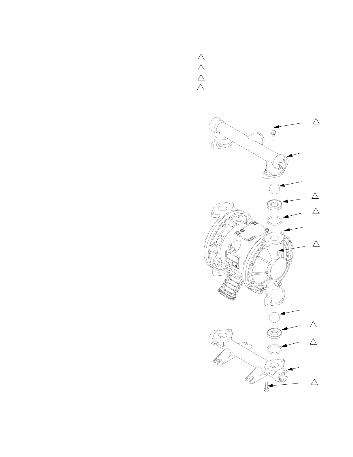
Disassembly of Inlet and Outlet Manifolds
1. Relieve the pressure, see page 2. Disconnect all
hoses.
2. Remove the pump from its mounting.
Installation
Apply medium-strength (blue) Loctite or equivalent to
1
the threads, and torque to 120-150 in-lb (14-17 N.m).
2
Arrow (A) must point toward outlet manifold (103).
3
Beveled seating surface must face the ball (301).
4
Not used on some models.
3. Remove the bolts (106) holding the outlet manifold
(103) to the fluid covers (101). See F
IG
. 1.
4. Remove the o-rings (202, not used on some models), seats (201), and balls (301) from manifold
(103).
5. Turn the pump over and remove the inlet manifold
(102). Remove the o-rings (202, not used on some
models), seats (201), and balls (301) from fluid covers (101).
1040 Model Shown
106
103
301
201
202
101
A
1
3
4
2
301
201
3
202
4
102
106
1
F
. 1
IG
309643B 3
Page 4
Installation
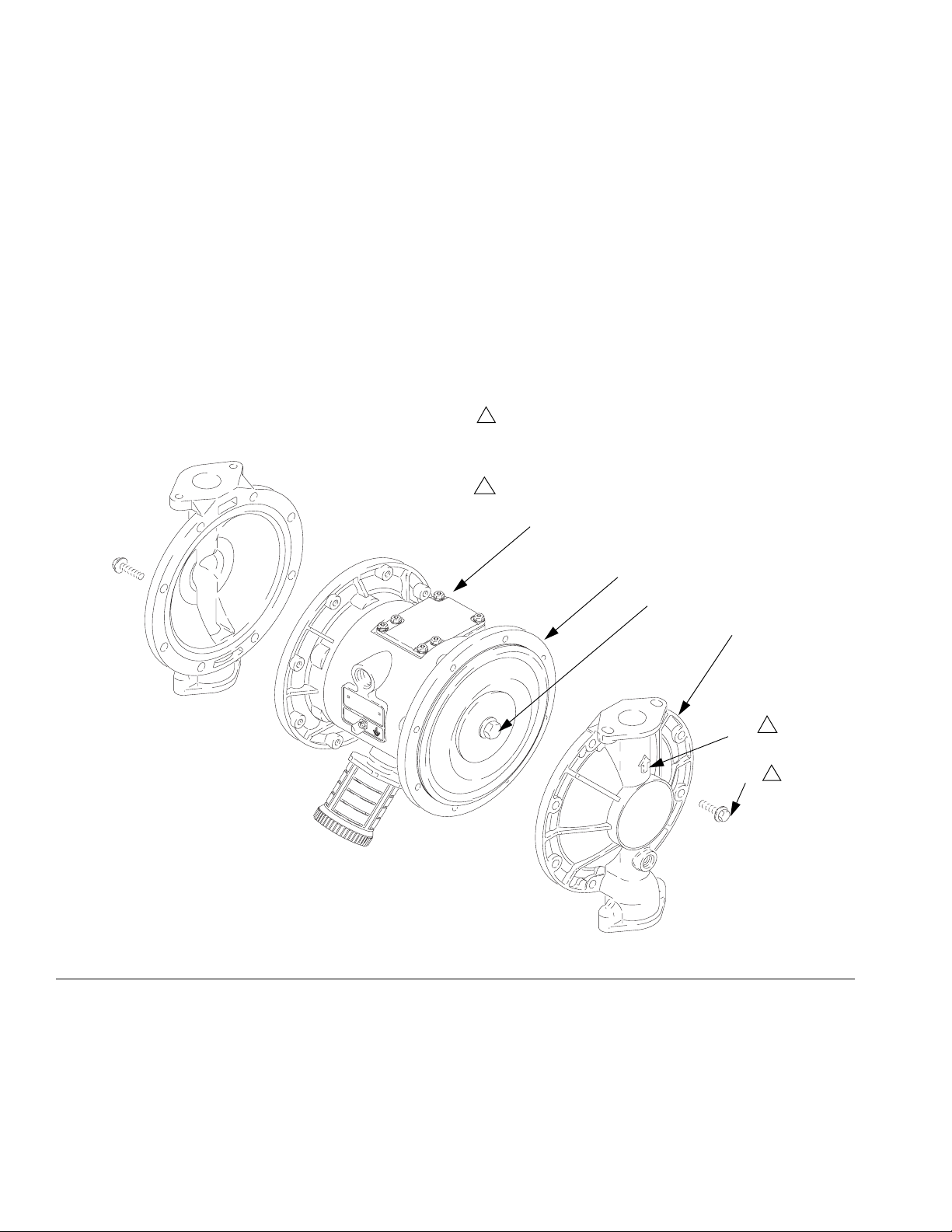
Disassembly of Fluid Covers
1. Remove the screws (106) holding the fluid covers
(101) to the air covers (23). Pull the fluid covers
(101) off the pump. See F
2. Loosen but do not remove the diaphragm shaft bolts
(107) on both ends.
IG
. 2.
3. Unscrew one bolt from diaphragm shaft (24) and
remove the o-ring (108), fluid side diaphragm plate
(105), PTFE diaphragm (403, used on PTFE mod-
els only), diaphragm (401), and air side diaphragm
plate (104). See F
IG
. 3
4. Pull the other diaphragm assembly and the diaphragm shaft (24) out of the center housing (1).
Hold the shaft flats with a open end wrench, and
remove the bolt (107) from the shaft. Disassemble
the remaining diaphragm assembly.
5. Clean and check all parts for wear or damage.
Replace parts as needed.
.
Apply medium-strength (blue) Loctite or equivalent to
1
the threads, and torque:
1040 models -120-150 in-lb (14-17 N.m.)
1590/2150 models - 190-220 in-lb (22-25 N.m.)
Arrow (A) must point toward air valve (B).
2
B
23
FIG. 2
107
101
A
106
2
1
4 309643B
Page 5

Installation
.
1
24
4
104
2
401
3
Cutaway View, with Diaphragms in Place
4
24
104
105
2
2
107
5
19
402
1
403
3
6
1
Cutaway View, with Diaphragms Removed
401
3
FIG. 3
403
3
6
105
2
108
107
5
1
24
4
1
Lips face out of housing (1).
2
Rounded side faces diaphragm (401).
3
Air Side must face center housing (1).
4
Grease.
5
Apply medium-strength (blue) Loctite® or
equivalent. Torque to 20-25 ft-lb (27-34 N.m)
at 100 rpm maximum.
6
Used on pumps with PTFE diaphragms
only.
309643B 5
Page 6

Installation
Reassembly of Fluid Covers
1. Install the diaphragm assembly on one end of the
shaft as follows:
a. Install new o-ring (108), provided with kit, on the
shaft bolt (107).
b. Install the fluid side diaphragm plate (105) on
the bolt so the rounded side faces the diaphragm (401).
c. On PTFE models only, install the PTFE dia-
phragm (403) with the side marked AIR SIDE
facing the center housing (1).
d. Install the diaphragm (401) on the bolt with the
side marked AIR SIDE facing the center housing (1).
e. Install the air side diaphragm plate (104) so the
rounded side faces the diaphragm (401). This
plate is used on all models, and is stamped with
its part number.
2. Grease the length and ends of diaphragm shaft
(24), and slide it through the new Stainless Steel
Plus housing (1).
3. Assemble the other diaphragm assembly to the
shaft as explained in step 1.
4. Hold one shaft bolt (107) with a wrench and torque
the other bolt to 20-25 ft-lb (27-34 N.m) at 100 rpm
maximum.
5. Align the fluid covers (101) and the center housing
(1) so the arrows (A) on the covers face the same
direction as the air valve (B). Apply
medium-strength (blue) Loctite or equivalent to the
threads of the screws (106). Secure the covers with
the screws handtight. See F
6. Torque the screws oppositely and evenly to:
1040 models -120-150 in-lb (14-17 N.m.)
1590/2150 models - 190-220 in-lb (22-25 N.m.)
IG
. 2.
Reassembly of the Inlet and Outlet
Manifolds
1. Reassemble in reverse order, following all notes in
IG
F
. 1.
f. Apply medium-strength (blue) Loctite or equiva-
lent to the bolt (107) threads. Screw the bolt into
the shaft (24) hand tight.
g. Inspect the wrench flats on the shaft (24) for
burrs that could damage the air motor seals
(402). Use a file to remove any burrs.
2. If o-rings (202) are used, replace with new ones to
assure the pump will seal properly. Be sure the ball
checks and manifolds are assembled exactly as
shown. The arrows (A) on the fluid covers(101)
must point toward the outlet manifold (103).
6 309643B
Page 7

Plastic Fluid Section Pumps
Disassembly of Inlet and Outlet Manifolds
1. Relieve the pressure, page 2. Disconnect all
hoses.
2. Remove the pump from its mounting.
3. Remove the bolts (106) holding the outlet manifold
(103) to the fluid covers (101). See F
4. Remove the o-rings (202, not used on some models), seats (201), and balls (301) from manifold
(103).
5. Turn the pump over and remove the inlet manifold
(102). Remove the o-rings (202, not used on some
models), seats (201), and balls (301) from fluid covers (101).
IG
. 4.
Installation
Torque to 80 to 90 in-lb (9 to 10 N.m)
1
Arrow (A) must point toward outlet manifold (103).
2
3
Not used on some models.
4
Beveled seating surface must face the ball (301).
106
1
103
301
201
202
301
201
202
4
A
4
3
3
2
101
102
112
1
F
. 4
IG
309643B 7
Page 8

Installation
Disassembly of Fluid Covers
1. Remove the screws (106) and (112) holding the fluid
covers (101) to the air covers (23). Pull the fluid covers (101) off the pump. See F
2. Unscrew one outer plate (105) from diaphragm
shaft (24), diaphragm (401), and air side diaphragm
plate (104). See F
112
1
IG
. 6.
IG
. 5.
3. Pull the other diaphragm assembly and the diaphragm shaft (24) out of the center housing (1).
Hold the shaft flats with a open end wrench, and
remove the other outer plate (105) from the shaft.
Disassemble the remaining diaphragm assembly.
4. Clean and check all parts for wear or damage.
Replace parts as needed.
You must torque the eight long screws (106) first,
1
then short screws (112). Torque the screws, (106)
first, then (112) oppositely and evenly to:
1040 models -100-150 in-lb (11-17 N.m.)
1590/2150 models - 190-220 in-lb (22-25 N.m.
Arrow (A) must point toward air valve (B).
2
B
23
113
101
A
106
2
1
F
. 5
IG
8 309643B
Page 9

Installation
19
402
1
105
2
403
3
1
24
4
104
2
401
3
6
1
24
4
104
2
401
3
403
6
3
5
105
1
24
4
Lips face out of housing (1).
1
Rounded side faces diaphragm (401).
2
Air Side must face center housing (1).
3
Grease.
4
5
Apply medium-strength (blue) Loctite® or
equivalent. Torque to 20-25 ft-lb (27-34 N.m)
at 100 rpm maximum.
6
Used on pumps with PTFE diaphragms
only.
. 6
F
IG
309643B 9
Page 10

Installation
Reassembly of Fluid Covers
1. Inspect the wrench flats on the shaft (24) for burrs
that could damage the air motor seals (402). Use a
file to remove any burrs.
2. Grease the length and ends of diaphragm shaft
(24), and slide it through the new Stainless Steel
Plus housing (1).
3. Assemble the inner diaphragm plates (104), dia-
phragms (401), PTFE diaphragms (403, if present),
and outer diaphragm plates (105) exactly as shown
in Fig. 6. These parts must be assembled correctly.
4. Apply medium-strength (blue Loctite or equivalent to
the threads of the fluid-side plate (105). Hold one of
the outer plates (105) with a wrench, and torque the
other outer plate to 20-25 ft-lb (27-34 N.m.) at 100
rpm maximum. Do not over-torque.
5. Align the fluid covers (101) and the center housing
(1) so the arrows (A) on the covers face the same
direction as the air valve (B). Apply
medium-strength (blue) Loctite or equivalent to the
threads of the screws (106) and (112). Place the
bolt caps (113) on the longer screws (106). Secure
the covers with the screws handtight. See F
6. Torque the screws, (106) first, then (112) oppositely
and evenly to:
1040 models -100-150 in-lb (11-17 N.m.)
1590/2150 models - 190-220 in-lb (22-25 N.m.)
IG
. 2.
Reassembly of the Inlet and Outlet
Manifolds
1. Reassemble in reverse order, following all notes in
IG
F
. 4.
2. If o-rings (202) are used, replace with new ones to
assure the pump will seal properly. Be sure the ball
checks and manifolds are assembled exactly as
shown. The arrows (A) on the fluid (101) must point
toward the outlet manifold (103).
10 309643B
Page 11

Installation
309643B 11
Page 12

Graco Standard Warranties
Graco Standard Husky Pump Warranty
Graco warrants all equipment manufactured by Graco and bearing its name to be free from defects in material and workmanship on the date of
sale by an authorized Graco distributor to the original purchaser for use. With the exception of any special, extended, or limited warranty published
by Graco, Graco will, for a period of five years from the date of sale, repair or replace any part of the equipment determined by Graco to be
defective. This warranty applies only when the equipment is installed, operated and maintained in accordance with Graco's written
recommendations.
This warranty does not cover, and Graco shall not be liable for general wear and tear, or any malfunction, damage or wear caused by faulty
installation, misapplication, abrasion, corrosion, inadequate or improper maintenance, negligence, accident, tampering, or substitution of
non-Graco component parts. Nor shall Graco be liable for malfunction, damage or wear caused by the incompatibility of Graco equipment with
structures, accessories, equipment or materials not supplied by Graco, or the improper design, manufacture, installation, operation or maintenance
of structures, accessories, equipment or materials not supplied by Graco.
This warranty is conditioned upon the prepaid return of the equipment claimed to be defective to an authorized Graco distributor for verification of
the claimed defect. If the claimed defect is verified, Graco will repair or replace free of charge any defective parts. The equipment will be returned
to the original purchaser transportation prepaid. If inspection of the equipment does not disclose any defect in material or workmanship, repairs
will be made at a reasonable charge, which charges may include the costs of parts, labor, and transportation.
THIS WARRANTY IS EXCLUSIVE, AND IS IN LIEU OF ANY OTHER WARRANTIES, EXPRESS OR IMPLIED, INCLUDING BUT NOT LIMITED
TO WARRANTY OF MERCHANTABILITY OR WARRANTY OF FITNESS FOR A PARTICULAR PURPOSE.
Graco's sole obligation and buyer's sole remedy for any breach of warranty shall be as set forth above. The buyer agrees that no other remedy
(including, but not limited to, incidental or consequential damages for lost profits, lost sales, injury to person or property, or any other incidental or
consequential loss) shall be available. Any action for breach of warranty must be brought within six years of the date of sale.
Graco makes no warranty, and disclaims all implied warranties of merchantability and fitness for a particular purpose in connection with
accessories, equipment, materials or components sold but not manufactured by Graco. These items sold, but not manufactured by Graco (such
as electric motors, switches, hose, etc.), are subject to the warranty, if any, of their manufacturer. Graco will provide purchaser with reasonable
assistance in making any claim for breach of these warranties.
In no event will Graco be liable for indirect, incidental, special or consequential damages resulting from Graco supplying equipment hereunder, or
the furnishing, performance, or use of any products or other goods sold hereto, whether due to a breach of contract, breach of warranty, the
negligence of Graco, or otherwise.
FOR GRACO CANADA CUSTOMERS
The parties acknowledge that they have required that the present document, as well as all documents, notices and legal proceedings entered into,
given or instituted pursuant hereto or relating directly or indirectly hereto, be drawn up in English. Les parties reconnaissent avoir convenu que la
rédaction du présente document sera en Anglais, ainsi que tous documents, avis et procédures judiciaires exécutés, donnés ou intentés à la suite
de ou en rapport, directement ou indirectement, avec les procedures concernées.
Extended Product Warranty
Graco warrants all Husky 205, 307, 515, 716, 1040, 1590, 2150, and 3275 air valve center sections to be free from defects in material and
workmanship for a period of fifteen years from date installed in service by the original purchaser. Normal wear of items such as packings or seals
are not considered to be defects in material and workmanship.
Five yearsGraco will provide parts and labor. Six to Fifteen yearsGraco will replace defective parts only.
Graco Information
TO PLACE AN ORDER, contact your Graco distributor, or call this number to identify the distributor closest to you:
1-800-367-4023 Toll Free; 612-623-6921; 612-378-3505 Fax
All written and visual data contained in this document reflects the latest product information available at the time of publication.
Graco reserves the right to make changes at any time without notice.
Sales Offices: Minneapolis, Detroit
International Offices: Belgium Korea, Hong Kong, Japan
GRACO INC. P.O. BOX 1441 MINNEAPOLIS, MN 55440-1441
www.graco.com
Printed in USA 309643A 10/2002
 Loading...