

Page 1
INSTRUCTIONS-PARTS LIST
308–807
This manual contains important
warnings and information.
READ AND KEEP FOR REFERENCE.
INSTRUCTIONS
First choice when
quality counts.t
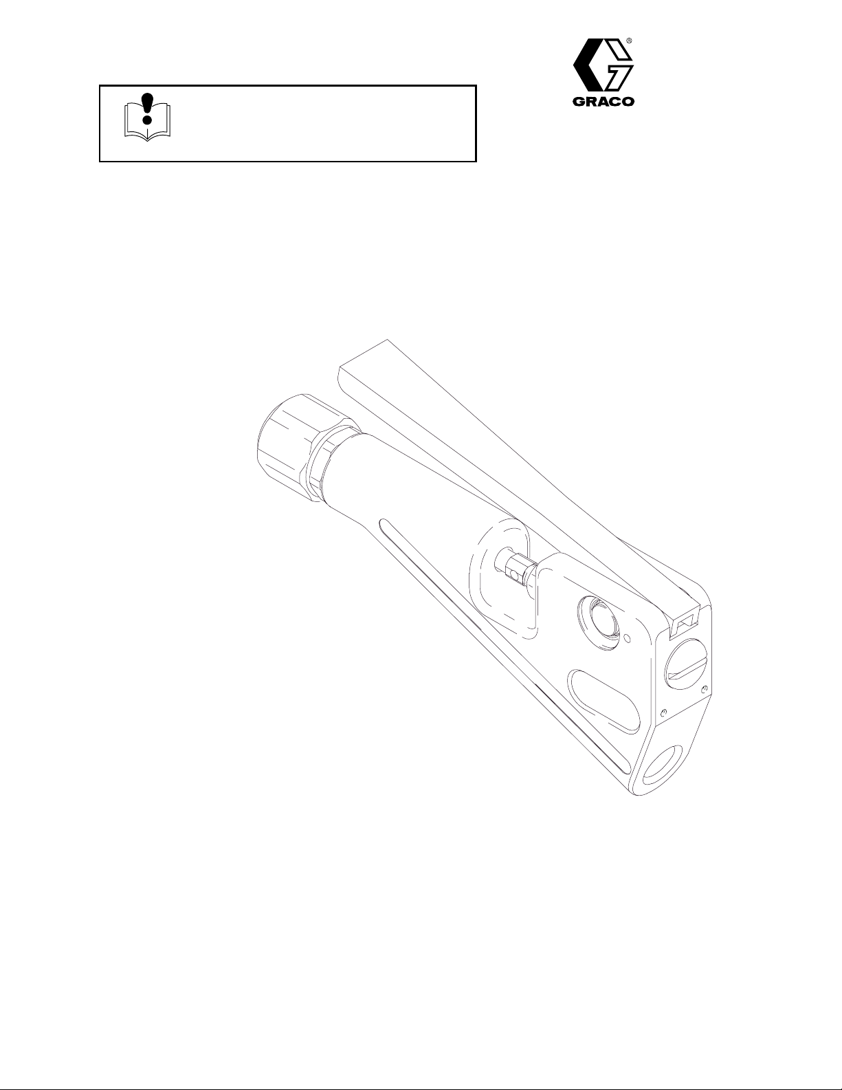
Ultra-Litet In-Line Flow Gun
3400 psi (23.4 MPa, 234 bar) Maximum Working Pressure
Model 240–199
With Ball End Needle
Model 240–200
With Tapered Needle
Rev. B
Supersedes A
GRACO INC. P.O. BOX 1441 MINNEAPOLIS, MN 55440–1441
Graco Inc. is registered to I.S. EN ISO 9001
7903A
Page 2
Table of Contents
Symbols
Warnings 2. . . . . . . . . . . . . . . . . . . . . . . . . . . . . . . . . . . . . .
Installation 4. . . . . . . . . . . . . . . . . . . . . . . . . . . . . . . . . . . . .
Operation 5. . . . . . . . . . . . . . . . . . . . . . . . . . . . . . . . . . . . .
Service 6. . . . . . . . . . . . . . . . . . . . . . . . . . . . . . . . . . . . . . .
Parts 7. . . . . . . . . . . . . . . . . . . . . . . . . . . . . . . . . . . . . . . . .
Technical Data 8. . . . . . . . . . . . . . . . . . . . . . . . . . . . . . . . .
Warranty 12. . . . . . . . . . . . . . . . . . . . . . . . . . . . . . . . . . . . .
Graco Phone Numbers 12. . . . . . . . . . . . . . . . . . . . . . . . .
WARNING
INJECTION HAZARD
Spray from the gun, hose leaks, or ruptured components can inject fluid into your body and cause an
extremely serious injury, including the need for amputation. Splashing fluid in the eyes or on the skin
can also cause a serious injury.
Warning Symbol
WARNING
This symbol alerts you to the possibility of serious
injury or death if you do not follow the corresponding
instructions.
Caution Symbol
CAUTION
This symbol alerts you to the possibility of damage to
or destruction of equipment if you do not follow the corresponding instructions.
D Fluid injected into the skin might look like just a cut, but it is a serious injury. Get immediate medi-
cal attention.
D Do not point the gun at anyone or at any part of the body.
D Do not put your hand or fingers over the gun nozzle.
D Do not stop or deflect leaks with your hand, body, glove or rag.
D Do not “blow back” fluid; this is not an air spray system.
D Be sure the gun trigger safety operates before dispensing.
D Lock the gun trigger safety when you stop dispensing.
D Follow the Pressure Relief Procedure on page 5 if the gun nozzle clogs and before cleaning,
checking or servicing the equipment.
D Tighten all fluid connections before operating the equipment.
D Check the hoses, tubes, and couplings daily. Replace worn, damaged, or loose parts immediately.
Permanently coupled hoses cannot be repaired; replace the entire hose.
TOXIC FLUID HAZARD
Hazardous fluid or toxic fumes can cause serious injury or death if splashed in the eyes or on the skin,
inhaled, or swallowed.
D Know the specific hazards of the fluid you are using.
D Store hazardous fluid in an approved container. Dispose of hazardous fluid according to all local,
D Always wear protective eyewear, gloves, clothing and respirator as recommended by the fluid and
2 308-807
state and national guidelines.
solvent manufacturer.
Page 3
WARNING
EQUIPMENT MISUSE HAZARD
Equipment misuse can cause the equipment to rupture or malfunction and result in serious injury.
D This equipment is for professional use only.
D Read all instruction manuals, tags, and labels before operating the equipment.
D Use the equipment only for its intended purpose. If you are uncertain about usage, call your Graco
distributor.
D Do not alter or modify this equipment. Use only genuine Graco parts and accessories.
D Check equipment daily. Repair or replace worn or damaged parts immediately.
D Do not exceed the maximum working pressure of the lowest rated system component. This equip-
ment has a 3400 psi (23.4 MPa, 234 bar) maximum working pressure.
D Route hoses away from traffic areas, sharp edges, moving parts, and hot surfaces. Do not expose
Graco hoses to temperatures above 66_C (150_F) or below –40_C (–40_F).
D Do not use the hoses to pull the equipment.
D Use only Graco approved hoses. Do not remove hose spring guards, which help protect the hose
from rupture caused by kinks or bends near the couplings.
D Use fluids or solvents that are compatible with the equipment wetted parts. See the Technical
Data section of all the equipment manuals. Read the fluid and solvent manufacturer’s warnings.
D Never use 1.1.1–trichloroethane, methylene chloride, other halogenated hydrocarbon solvents or
fluids containing such solvents in pressurized aluminum equipment. Such use could result in a
chemical reaction, with the possibility of explosion.
D Comply with all applicable local, state, and national fire, electrical, and safety regulations.
FIRE AND EXPLOSION HAZARD
Improper grounding, poor ventilation, open flames or sparks can cause a hazardous condition and result in a fire or explosion and serious injury.
D Ground the equipment. Refer to Grounding on page 4.
D If there is any static sparking or you feel an electric shock while using this equipment, stop dis-
pensing immediately. Do not use the equipment until you identify and correct the problem.
D Provide fresh air ventilation to avoid the buildup of flammable fumes from solvents or the fluid
being dispensed.
D Keep the dispense area free of debris, including solvent, rags, and gasoline.
D Before operating this equipment, electrically disconnect all equipment in the dispense area.
D Before operating this equipment, extinguish all open flames or pilot lights in the dispense area.
D Do not smoke in the dispense area.
D Do not turn on or off any light switch in the dispense area while dispensing or while operating if
fumes are present.
D Do not operate a gasoline engine in the dispense area.
3308-807
Page 4
Installation
Grounding
WARNING
FIRE AND EXPLOSION HAZARD
Before operating the pump, ground the
system as explained below. Also read
the section FIRE AND EXPLOSION
HAZARD on page 3.
1. Pump: use a ground wire and clamp as shown in
your separate pump manual.
2. Fluid hoses: use only electrically conductive fluid
hoses with a maximum of 500 feet (150 m) combined hose length to ensure grounding continuity.
Check the electrical resistance of your fluid hoses
at least once a week. If your hose does not have a
tag on it which specifies the maximum electrical
resistance, contact the hose supplier or manufacturer for the maximum resistance limits. If the hose
resistance exceeds the recommended limits,
replace it immediately.
3. Air compressors and hydraulic power supplies:
ground the equipment according to the manufacturer’s recommendations.
4. Flow gun: ground through connection to a properly
grounded fluid hose and pump.
5. Fluid supply container: Ground according to your
local code.
6. Flammable liquids in the dispensing area: must be
kept in approved, grounded containers. Do not
store more than the quantity needed for one shift.
7. Solvent pails used when flushing: follow your local
code. Use only metal pails, which are conductive,
placed on a grounded surface. Do not place the
pail on a nonconductive surface, such as paper or
cardboard, which interrupts the grounding continuity.
8. To maintain grounding continuity when flushing or
relieving pressure, hold a metal part of the gun
firmly to the side of a grounded metal pail, then
trigger the gun.
4 308-807
Page 5

Operation
Pressure Relief Procedure
WARNING
INJECTION HAZARD
The system pressure must be manually
relieved to prevent the system from
starting or dispensing accidentally. Fluid
under high pressure can be injected through the
skin and cause serious injury. To reduce the risk of
an injury from injection, splashing fluid, or moving
parts, follow the Pressure Relief Procedure
whenever you:
D are instructed to relieve the pressure,
D stop dispensing,
D check or service any of the system equipment,
D or install or clean the nozzle.
1. Fully release the gun trigger. Press the red button
to lock the trigger safety. See Fig. 1.
2. Shut off the fluid supply pump.
3. Hold a metal part of the gun firmly to the side of a
grounded metal pail. Press the silver button to
unlock the trigger safety. Trigger the gun to relieve
pressure.
4. Open the pump drain valve to help relieve pressure in the pump, hose, and gun. Triggering the
gun to relieve pressure may not be sufficient. Have
a container ready to catch the drainage.
5. Leave the drain valve open until you are ready to
dispense again.
Flow Rate Adjustment
WARNING
To reduce the risk of serious injury, whenever the
gun is not in use, press the red button to lock the
trigger safety. See Fig. 1.
7901
Trigger Safety
Locked
Fig. 1
To dispense material, unlock the trigger safety, then
fully squeeze the trigger. Flow begins with the slightest
pressure and continues until the trigger is released.
NOTE: A minimum of 1 pint (0.5 liters) of material
must be dispensed from the gun to remove all air from
the system. If the air is not completely removed, slow
shutoff may occur.
Adjust the pump to the minimum speed necessary to
deliver the material at a satisfactory rate, or adjust the
fluid/mastic regulator.
Lubrication and Care
Trigger Safety
Unlocked
6. Fully release the gun trigger and lock the trigger
safety.
Keep the gun clean, and oil the exposed portion of the
needle with a light, high grade machine oil daily.
5308-807
Page 6

Service
NOTE: Repair kits are available. See page 7 for the
kits for your gun model. For the best results, use all
the new parts in the kit. Kit parts are marked with an
asterisk, for example (2*).
NOTE: See the Parts Drawing on page 7 when
disassembling and reassembling the gun.
Disassembly
WARNING
To reduce the risk of serious injury whenever you
are instructed to relieve pressure, always follow the
Pressure Relief Procedure on page 5.
1. Relieve the pressure.
2. Disconnect the gun from the hose.
3. Unscrew the nozzle nut (11) and nozzle (not
shown) from the seat (5*).
4. Unlock the trigger safety. See Fig. 1.
5. Depress the trigger (3) and remove the seat (5*)
from the gun.
CAUTION
Failure to depress the trigger while removing the seat
may damage the needle.
6. Loosen the hexnut (12) on the needle (2*) while
holding the adjustment screw (A) with a screwdriver.
7. Unscrew the needle (2*) by turning the adjustment
screw (A) until the needle is unthreaded.
Reassembly
1. Apply grease to the needle (2*) o-rings.
2. Put the needle (2*) in the gun, screwing the hexnut
(12) on the needle as it is going in.
3. Start threading the adjustment screw (A) until it
engages the threads of the needle (2). Continue
threading until the trigger (3) raises 1/2 in. (13
mm).
4. Grease the threads of the seat (5*) and the gasket
(10*)
5. Press the trigger (3) and install the gasket (10*)
and seat (5*).
6. Lift the trigger (3) and lock the trigger safety.
7. Trigger adjustment:
a. Turn the adjustment screw (A) clockwise until
the trigger (3) travels as far up as possible.
b. Turn the adjustment screw (A) counterclock-
wise until the trigger (3) stops falling, then turn
an additional 1/8 turn.
c. Tighten the hexnut (12) against the adjustment
screw (A). Hold the adjustment screw (A) to
prevent it from turning. Torque the hexnut to
18–22 in-lb (2.03–2.46 NSm).
d. Test the trigger safety (B) to ensure that it
operates properly. If the trigger safety does not
operate properly, loosen the hexnut (12) and
return to step 7a.
8. Remove the hexnut (12) and remove the needle
(2*) through the front of the gun.
6 308-807
8. Screw the nozzle nut (11) and nozzle (not shown)
back onto the front of the gun.
Page 7

11
Parts
5
2
1
Grease the needle o-rings.
1
2
T orque to 18–22 in-lb (2.03–2.46 NSm).
Models 240–199 and 240–200
Ref
No. Part No. Description Qty
1 240–208 BODY, Flow Gun 1
2* 240–201 NEEDLE, 3/16 ball
Model 240–199 only 1
240–202 NEEDLE, tapered
Model 240–200 only 1
3114–330 TRIGGER 1
5* 240–204 SEA T, 3/16 ball
Model 240–199 only 1
240–205 SEA T, tapered needle
Model 240–200 only 1
6 192–989 SCREW, pivot 1
10* 168–845 GASKET, copper 1
11 188–253 NUT, nozzle 1
12 114–357 NUT, hex 1
* Included in repair kit. Keep these parts on hand to reduce
down-time.
10
1
Repair Kits
Kit No. and
Description
240–206
For Model
240–199
240–207
For Model
240–200
3
12
2
B
Includes:
Ref. No. Part No. Description
2
5
10
2
5
10
240–201
240–204
168–845
240–202
240–205
168–845
NEEDLE, 3/16 ball
SEAT
GASKET
NEEDLE, tapered
SEAT
GASKET
6
A
7904A
7308-807
Page 8

Technical Data
Category Data
Maximum working pressure 3400 psi (23.4 MPa, 234 bar)
Maximum temperature 120_ F (49_ C)
Flow rate at 2000 psi (14 MPa, 138 bar)* Model 240–199: 158 oz/min (4.5 kg/min)
Model 240–200: 154 oz/min (4.4 kg/min)
Outlet port size 1/4 npt(f) and flange
Inlet port size 1/4 npt(f)
Dry weight Model 240–199: 11.6 oz (325 gm)
Model 240–200: 11.6 oz (325 gm)
Length 5.9 in (15.0 cm)
Width 2.6 in (6.6 cm)
Thickness 0.85 in (2.16 cm)
Pressure vessel material Aluminum
Pressure vessel ID 0.25 in (6.4 mm)
Gun seat diameter Model 240–199: 0.125 in (3.2 mm)
Model 240–200: 0.203 in (5.2 mm)
Needle seat type Model 240–199: Carbide ball
Model 240–200: 7_ Tapered carbide
Inlet/outlet angle 20_
Trigger force – breakaway @ 1000 psi
(7 MPa, 69 bar)
Trigger force – breakaway @ 2000 psi
(14 MPa, 138 bar)
Trigger force – sustaining Model 240–199: 3.2 lb (1.45 kg)
Wetted parts Aluminum, stainless steel, carbide, polyethylene, CV75r
Model 240–199: 1.6 lb (0.73 kg)
Model 240–200: 3.8 lb (1.72 kg)
Model 240–199: 2.2 lb (1.0 kg)
Model 240–200: 7.3 lb (3.31 kg)
Model 240–200: 2.8 lb (1.27 kg)
CV75r is a registered trademark of the International Seal Co., Inc.
* Flow rates were measured using PVC sealer dispensed through a 1/8 in. diameter orifice nozzle and z-swivel con-
nected to inlet. Actual flow rates will vary depending on material type, fluid pressure, nozzle size, and system configuration.
8 308-807
Page 9

Notes
9308-807
Page 10

Notes
10 308-807
Page 11

Notes
11308-807
Page 12

Graco Standard Warranty
Graco warrants all equipment manufactured by Graco and bearing its name to be free from defects in material and workmanship on the
date of sale by an authorized Graco distributor to the original purchaser for use. With the exception of any special, extended, or limited
warranty published by Graco, Graco will, for a period of twelve months from the date of sale, repair or replace any part of the equipment
determined by Graco to be defective. This warranty applies only when the equipment is installed, operated and maintained in accordance with Graco’s written recommendations.
This warranty does not cover, and Graco shall not be liable for general wear and tear, or any malfunction, damage or wear caused by
faulty installation, misapplication, abrasion, corrosion, inadequate or improper maintenance, negligence, accident, tampering, or substitution of non–Graco component parts. Nor shall Graco be liable for malfunction, damage or wear caused by the incompatibility of
Graco equipment with structures, accessories, equipment or materials not supplied by Graco, or the improper design, manufacture,
installation, operation or maintenance of structures, accessories, equipment or materials not supplied by Graco.
This warranty is conditioned upon the prepaid return of the equipment claimed to be defective to an authorized Graco distributor for
verification of the claimed defect. If the claimed defect is verified, Graco will repair or replace free of charge any defective parts. The
equipment will be returned to the original purchaser transportation prepaid. If inspection of the equipment does not disclose any defect
in material or workmanship, repairs will be made at a reasonable charge, which charges may include the costs of parts, labor, and
transportation.
THIS WARRANTY IS EXCLUSIVE, AND IS IN LIEU OF ANY OTHER W ARRANTIES, EXPRESS OR IMPLIED, INCLUDING BUT
NOT LIMITED TO WARRANTY OF MERCHANTABILITY OR W ARRANTY OF FITNESS FOR A PARTICULAR PURPOSE.
Graco’s sole obligation and buyer’s sole remedy for any breach of warranty shall be as set forth above. The buyer agrees that no other
remedy (including, but not limited to, incidental or consequential damages for lost profits, lost sales, injury to person or property , or any
other incidental or consequential loss) shall be available. Any action for breach of warranty must be brought within two (2) years of the
date of sale.
Graco makes no warranty, and disclaims all implied warranties of merchantability and fitness for a particular purpose in connection
with accessories, equipment, materials or components sold but not manufactured by Graco. These items sold, but not manufactured
by Graco (such as electric motors, switches, hose, etc.), are subject to the warranty, if any, of their manufacturer . Graco will provide
purchaser with reasonable assistance in making any claim for breach of these warranties.
In no event will Graco be liable for indirect, incidental, special or consequential damages resulting from Graco supplying equipment
hereunder, or the furnishing, performance, or use of any products or other goods sold hereto, whether due to a breach of contract,
breach of warranty , the negligence of Graco, or otherwise.
FOR GRACO CANADA CUSTOMERS
The parties acknowledge that they have required that the present document, as well as all documents, notices and legal proceedings
entered into, given or instituted pursuant hereto or relating directly or indirectly hereto, be drawn up in English. Les parties reconnaissent avoir convenu que la rédaction du présente document sera en Anglais, ainsi que tous documents, avis et procédures judiciaires
exécutés, donnés ou intentés à la suite de ou en rapport, directement ou indirectement, avec les procedures concernées.
Graco Phone Number
TO PLACE AN ORDER, contact your Graco distributor, or call this number to identify the distributor closest to you:
1–800–367–4023 T oll Free
All written and visual data contained in this document reflects the latest product information available at the time of publication.
Graco reserves the right to make changes at any time without notice.
Foreign Offices: Belgium, Canada, England, Korea, France, Germany , Hong Kong, Japan
Sales Offices: Minneapolis, Detroit, Los Angeles
GRACO INC. P.O. BOX 1441 MINNEAPOLIS, MN 55440–1441
http://www.graco.com
e1998–1997 Graco Inc. 308–807 Rev. B April 1998 PRINTED IN U.S.A.
12 308-807
Page 13

3X8–807
Rev. C
Supersedes Rev. B
Parts Change Notice
Some parts in Rev. B of manual 308–807 have changed but have not yet been changed in the
instruction manual. Please note the changes below and mark them in your manual or keep this
sheet with your manual.
Series
Letter
Assembly No.
All Models B 114–330 3 Trigger Replaced by Part No. 194–983 Trigger
Change
Other Changes
Page 1: Add: For use with fluids of viscosity less than 150,000 cps.
Before the Service Section: Add the following Troubleshooting Chart:
Part That
Changed
Ref
No. Part Description Description of Change
PROBLEM CAUSE SOLUTION
When using a small orifice wand
(approximately .040 in. diameter),
1/4 to 3/4 in. of material continues
to flow from the outlet of the
wand immediately after releasing
the trigger.
Popping, snapping, spitting, gaps,
or irregularities in the material
stream as it flows from the wand.
Gun does not shutoff completely. Needle is not fully seating. Readjust the trigger as described in
Air is trapped in the wand. Purge all air from the wand.
Helpful Tip: To verify that air is
trapped in the wand, trigger the gun,
then quickly shut off the material supply, relieve pressure in the gun, and
promptly remove the gun from the
supply hose. Then, without triggering
the gun, lay it on a bench and observe if material continues to flow
very slowly from the outlet of the
wand (approximately 0.1 in. per minute from a .050 in. orifice). If this occurs, there is air trapped in the wand.
Air in the material. Dispense material from the gun/wand
until the popping, snapping, and spitting has stopped and the bead/extrusion is smooth and uninterrupted.
steps 6 and 7 under Reassembly, on
page 6 of your manual.
All written and visual data contained in this document reflects the latest product information available at the
time of publication. Graco reserves the right to make changes at any time without notice.
July 8, 1999
13308-807
 Loading...