

Page 1
INSTRUCTIONS-PARTS LIST
Parts
307882
This manual contains important
warnings and information.
READ AND KEEP FOR REFERENCE.
INSTRUCTIONS
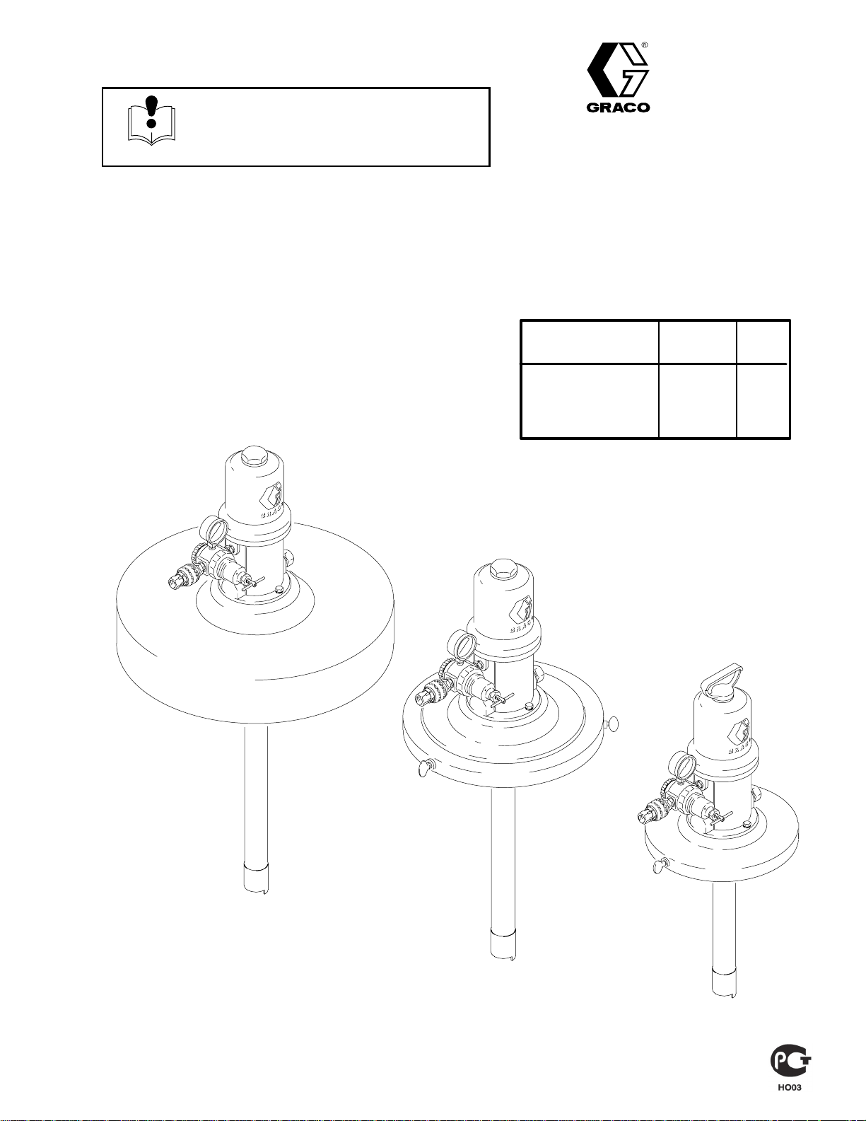
15:1 Ratio Fire-Ball
LUBRICATION PUMPS
2750 psi (18.9 MPa, 189 bar) Maximum Working Pressure
MODEL 220171
Rev. F
First choice when
quality counts.t
Dispense
Model No. Size Kit Cover
222078 35 lb X X
220170 120 lb X X
220171 400 lb X X
MODEL 220170
TI1018
MODEL 222078
TI1016
TI1014
GRACO INC. P.O. BOX 1441 MINNEAPOLIS, MN 55440–1441
ECOPYRIGHT 1988, GRACO INC.
Graco Inc. is registered to I.S. EN ISO 9001
Page 2
Table of Contents
Warnings 3. . . . . . . . . . . . . . . . . . . . . . . . . . . . . . . . . . . . . .
Setup 5. . . . . . . . . . . . . . . . . . . . . . . . . . . . . . . . . . . . . . . . .
Operation 7. . . . . . . . . . . . . . . . . . . . . . . . . . . . . . . . . . . . .
Parts
Model 222078 8. . . . . . . . . . . . . . . . . . . . . . . . . . . . . . . . .
Dispense Kit 222080 8. . . . . . . . . . . . . . . . . . . . . . . . . . . .
Model 220170 9. . . . . . . . . . . . . . . . . . . . . . . . . . . . . . . . .
Dispense Kit 222081 9. . . . . . . . . . . . . . . . . . . . . . . . . . . .
Model 220171 10. . . . . . . . . . . . . . . . . . . . . . . . . . . . . . . .
Graco Warranty 12. . . . . . . . . . . . . . . . . . . . . . . . . . . . . . .
Graco Phone Number 12. . . . . . . . . . . . . . . . . . . . . . . . . .
WARNING
FIRE AND EXPLOSION HAZARD
These systems are designed to be used
ONLY in pumping non-corrosive and
non-abrasive lubricants and greases.
Any other use of the system can cause
unsafe operating conditions and result in
component rupture, fire or explosion
which can cause serious bodily injury, including
fluid injection.
2 307882
Page 3
Symbols
Warning Symbol
WARNING
This symbol alerts you to the possibility of serious
injury or death if you do not follow the instructions.
WARNING
EQUIPMENT MISUSE HAZARD
Equipment misuse can cause the equipment to rupture or malfunction and result in serious injury.
INSTRUCTIONS
D This equipment is for professional use only.
D Read all instruction manuals, tags, and labels before you operate the equipment.
D Use the equipment only for its intended purpose. If you are not sure, call your Graco distributor.
D Do not alter or modify this equipment. Use only Graco parts and accessories.
D Check equipment daily. Repair or replace worn or damaged parts immediately.
D Do not exceed the maximum working pressure stated on the equipment or in the Technical Data
section for your equipment. Do not exceed the maximum working pressure of the lowest rated
component in your system.
Caution Symbol
CAUTION
This symbol alerts you to the possibility of damage to
or destruction of equipment if you do not follow the
instructions.
D Use fluids and solvents that are compatible with the equipment wetted parts. See the Technical
Data section of all equipment manuals. Read the fluid and solvent manufacturer’s warnings.
D Wear hearing protection when you operate this equipment.
D Comply with all applicable local, state, and national fire, electrical, and safety regulations.
MOVING PARTS HAZARD
Moving parts, such as the priming piston and ram plate, can pinch or amputate your fingers.
D Keep clear of all moving parts when you start or operate the pump.
D Keep hands and fingers away from the priming piston during operation and whenever the pump is
charged with air.
D Keep your hands away from the ram plate and the lip of the drum while the ram is operating.
D Before you service the equipment, follow the Pressure Relief Procedure on page 7 to prevent
the equipment from starting unexpectedly.
TOXIC FLUID HAZARD
Hazardous fluid or toxic fumes can cause serious injury or death if splashed in the eyes or on the skin,
inhaled, or swallowed.
D Know the specific hazards of the fluid you are using.
D Store hazardous fluid in an approved container. Dispose of hazardous fluid according to all local,
state, and national guidelines.
D Always wear protective eyewear, gloves, clothing, and respirator as recommended by the fluid and
solvent manufacturer.
307882 3
Page 4
WARNING
INJECTION HAZARD
Spray from the spray gun/dispense valve, leaks, or ruptured components can inject fluid into your
body and cause extremely serious injury, including the need for amputation. Fluid splashed in the eyes
or on the skin can also cause serious injury.
D Fluid injected into the skin might look like just a cut, but it is a serious injury. Get immediate
medical attention.
D Do not point the gun/valve at anyone or at any part of the body.
D Do not put your hand or fingers over the spray tip/nozzle.
D Do not stop or deflect leaks with your hand, body, glove or rag.
D Do not “blow back” fluid; this is not an air spray system.
D Always have the tip guard and the trigger guard on the gun when spraying.
D Check the gun diffuser operation weekly. See the gun manual.
D Be sure the gun/valve trigger safety operates before you spray/dispense.
D Lock the gun/valve trigger safety when you stop spraying/dispensing.
D Follow the Pressure Relief Procedure on page 7 if the spray tip/nozzle clogs and before you
clean, check, or service the equipment.
D Tighten all fluid connections before you operate the equipment.
D Check the hoses, tubes, and couplings daily. Replace worn or damaged parts immediately. Do not
repair high pressure couplings; you must replace the entire hose.
D Fluid hoses must have spring guards on both ends to help protect them from rupture caused by
kinks or bends near the couplings.
FIRE AND EXPLOSION HAZARD
Improper grounding, poor ventilation, open flames, or sparks can cause a hazardous condition and
result in a fire or explosion and serious injury.
D Ground the equipment and the object being sprayed or dispensed to. See Grounding on page 5.
D If there is any static sparking or you feel an electric shock while using this equipment, stop
spraying/dispensing immediately. Do not use the equipment until you identify and correct the
problem.
D Provide fresh air ventilation to avoid the buildup of flammable fumes from solvents or the fluid
being sprayed/dispensed to.
D Keep the spray/dispense area free of debris, including solvent, rags, and gasoline.
D Electrically disconnect all equipment in the spray/dispense area.
D Extinguish all open flames or pilot lights in the spray/dispense area.
D Do not smoke in the spray/dispense area.
D Do not turn on or off any light switch in the spray/dispense area while operating or if fumes are
present.
D Do not operate a gasoline engine in the spray/dispense area.
United States Government safety standards have been adopted under the Occupational Safety and Health Act.
You should consult these standards––particularly General Standards, Part 1910, and Construction Standards, Part
1926.
4 307882
Page 5

Setup
Grounding
To reduce the risk of static sparking, ground the pump.
Check your local electrical code for detailed grounding
instructions for your area and type of equipment.
D Any pails used when flushing: Use only metal,
grounded pails when flushing. Make firm metal-tometal contact between a metal part of the dispensing valve and the pail. Use the lowest possible
pressure.
D Pump: Use ground wire and clamp as shown in
Fig. 1.
D Air and fluid hoses: Use only grounded hoses.
D Air compressor: Follow manufacturer’s recommen-
dations.
D Dispensing valve: Obtain grounding through con-
nection to a properly grounded fluid hose and
pump.
D Fluid supply container: Follow your local code.
D Object being lubricated: Follow your local code.
D To maintain grounding continuity when flushing or
relieving pressure, always hold a metal part of the
dispensing valve firmly to the side of a metal pail,
and then open the dispensing valve.
To ground the pump, loosen the grounding lug
locknut (W) and washer (X). Insert one end of a
12 ga (1.5 mm@) minimum ground wire (Y) into
the slot in the lug (Z), and tighten the locknut
securely. Connect the other end of the wire to a
true earth ground. See Fig. 1. To order a
ground wire and clamp, order Part No. 222011.
Z
Y
X
W
02464
Fig. 1
307882 5
Page 6

103
102
104
105
106
101
Setup
1
KEY
A Pump Ground Wire
B Main Air Supply Line
C Air Filter
D Air Line Lubricator
E Pump Runaway Valve
F Bleed-type Master Air Valve
101 Hose
102 Dispense Valve
103 Quick-disconnect Coupler
104 Quick-disconnect Nipple
105 Regulator
106 Nipple
107 Z-swivel
Detail A
B
107
TI1015
3
Fig 2
For All Models
Assemble the air and fluid lines as shown in Fig 2.
For Model 222078
Secure pump to cover (3) with the screws and lockwashers provided. Position the assembly on an
opened 35 lb pail. Tighten the thumbscrews firmly.
For Model 220170
Secure cover (3) to opened fluid container with the
thumbscrews provided. Insert the pump through the hole
in the cover and lower it into the container. It is not necessary to bolt the pump to the cover.
For Model 220171
Set cover (3) on open drum. Thumbscrews are not required. Insert the pump through the hole in the cover and
lower it into the drum. It is not necessary to bolt the pump
to the cover.
Air Line Accessories
Install the air line accessories in the order shown in
Fig 2. Detail A.
F
C
1. Install a bleed-type master air valve (F) to isolate the
accessories for service.
2. Install an air line filter (C) to remove harmful dirt and
contaminants from your compressed air supply.
3. Install an air line lubricator (D) for automatic air motor
lubrication.
4. Install a pump runaway valve (E) to shut off the air to
the pump if the pump accelerates beyond the preadjusted setting. A pump which runs too fast can be
seriously damaged.
5. Attach the quick disconnect coupler (103) to the air
supply hose.
E
105
D
103
A
CAUTION
Avoid hanging the air accessories directly on the pump
air inlet. The fittings are not strong enough to support
the accessories and may cause one or more to break.
If accessories must be installed directly on the pump,
provide a bracket on which to mount the accessories.
6 307882
Page 7

Operation
Pressure Relief Procedure
WARNING
INJECTION HAZARD
To reduce the risk of serious bodily
injury, including fluid injection, injury from
moving parts, or splashing in the eyes or
on the skin, always follow this procedure whenever
you shut off the pump, when checking or servicing
any part of the system, when installing or changing
dispensing devices, and whenever you stop dispensing.
1. Close the pump air regulator.
2. Close the pump’s bleed-type master air valve (re-
quired in the system).
3. Hold a metal part of the gun or valve firmly to a
grounded metal waste container and trigger to relieve the fluid pressure.
If you suspect that the dispensing valve is clogged, or
that pressure has not been fully relieved after following
the steps above, very slowly loosen the dispensing
valve coupler or hose end coupling to relieve pressure
gradually, then loosen completely. Then clear the clog.
Startup – Single or Multiple Pump Systems
1. Close the air regulators and bleed-type master air
valves to all but one pump.
2. Open the master air valve from the compressor.
3. For the pump which is connected, trigger the dispensing valve into a grounded metal waste container, making firm metal-to-metal contact between
the container and valve. Open the bleed-type master
air valve and open the pump air regulator slowly, just
until the pump is running. When the pump is primed
and all air has been pushed out of the lines, release
the trigger.
4. If you have more than one pump, repeat this procedure for each pump.
NOTE: When the pump is primed, and with sufficient air
supplied, the pump starts when the dispensing valve is
opened and shuts off when it is closed.
5. Set the air pressure to each pump at the lowest pressure needed to get the desired results. Use the regulator to adjust pump speed and pressure.
CAUTION
Never allow the pump to run dry of the fluid
being pumped. A dry pump quickly accelerates
to a high speed and could possibly damage
itself. If the pump accelerates quickly, stop it
immediately, and check the fluid supply. If the
supply container is empty and air has been
pumped into the lines, prime the pump and lines
with fluid, or flush it and leave it filled with a
compatible solvent. Be sure to eliminate all air
from the fluid system.
WARNING
The maximum working pressure of each pump in
your system may not be the same. To reduce the risk
of overpressurizing any part of your system, be sure
you know the maximum working pressure rating of
each pump and its connected components. Never
exceed the maximum working pressure of the lowest
rated component connected to a particular pump.
To determine the fluid output pressure using the air
regulator reading, multiply the ratio of the pump by
the air pressure shown on the regulator gauge. For
example:
10 (:1) ratio x 100 psi air =
1000 psi fluid output
[10:(1) ratio x 7 bar air = 70 bar fluid output]
Limit the air to the pump so that no air line or fluid line
component or accessory is overpressurized.
NOTE: A pump runaway valve (E) can be installed on the
air line to automatically shut off the pump if it starts to run
too fast.
7. Read and follow the instructions supplied with each
component in your system.
8. To shut off system, always relieve the pressure .
WARNING
INJECTION HAZARD
To reduce the risk of serious injury
whenever you are instructed to relieve
pressure, always follow the Pressure
Relief Procedure at left.
307882 7
Page 8

Parts
Model 222078
35 lb Pail Size
Ref
No. Part No. Description Qty
1 206405 PUMP, 15:1 Ratio Fire-Ball;
See 306531 for parts 1
2 222080 DISPENSE KIT; See parts at right 1
3 222058 COVER 1
106
105
104
Model 222080
Dispense Kit
Ref
No. Part No. Description Qty
101 109165 HOSE; 3/8” ID, cpld 1/4 npt (mbe),
15 ft (4.5 m) 1
102 242056 VALVE, dispense 1
103 110198 COUPLER, quick-disconnect; 3/8 npt(f) 1
104 169971 NIPPLE, quick-disconnect 1
105 110234 REGULATOR, air 1
106 156849 NIPPLE, 3/8 npt 1
107 202577 Z-SWIVEL 1
1
103
102
101
107
8 307882
TI1015
3
Page 9

Parts
Model 220170
120 lb Drum Size
Ref
No. Part No. Description Qty
1 206699 PUMP, 15:1 Ratio Fire-Ball;
See 306531 for parts 1
2 222081 DISPENSE KIT; See parts at right 1
3 204574 COVER; See 306345 for parts 1
1
106
105
104
103
Model 222081
Dispense Kit
Ref
No. Part No. Description Qty
101 109167 HOSE; 3/8” ID, cpld 1/4 npt (mbe),
25 ft (7.6 m) 1
102 242056 VALVE, dispense 1
103 110198 COUPLER, quick-disconnect; 3/8 npt(f) 1
104 169971 NIPPLE, quick-disconnect 1
105 110234 REGULATOR, air 1
106 156849 NIPPLE, 3/8 npt 1
107 202577 Z-SWIVEL 1
101
102
107
TI1017
3
307882 9
Page 10

Parts
Model 220171
400 lb Drum Size
Ref
No. Part No. Description Qty
1 206700 PUMP, 15:1 Ratio Fire-Ball;
See 306531 for parts 1
2 222081 DISPENSE KIT; See parts at right 1
3 200326 COVER 1
1
106
105
104
103
Model 222081
Dispense Kit
Ref
No. Part No. Description Qty
101 109167 HOSE; 3/8” ID, cpld 1/4 npt (mbe),
25 ft (7.6 m) 1
102 242056 VALVE, dispense 1
103 110198 COUPLER, quick-disconnect; 3/8 npt(f) 1
104 169971 NIPPLE, quick-disconnect 1
105 110234 REGULATOR, air 1
106 156849 NIPPLE, 3/8 npt 1
107 202577 Z-SWIVEL 1
101
102
107
3
TI1019
10 307882
Page 11

Notes
307882 11
Page 12

The Graco Standard Warranty
Graco warrants all equipment manufactured by Graco and bearing its name to be free from defects in material and workmanship on the
date of sale by an authorized Graco distributor to the original purchaser for use. With the exception of any special, extended, or limited
warranty published by Graco, Graco will, for a period of twelve months from the date of sale, repair or replace any part of the equipment
determined by Graco to be defective. This warranty applies only when the equipment is installed, operated and maintained in accordance with Graco’s written recommendations.
This warranty does not cover, and Graco shall not be liable for general wear and tear, or any malfunction, damage or wear caused by
faulty installation, misapplication, abrasion, corrosion, inadequate or improper maintenance, negligence, accident, tampering, or substitution of non-Graco component parts. Nor shall Graco be liable for malfunction, damage or wear caused by the incompatibility of
Graco equipment with structures, accessories, equipment or materials not supplied by Graco, or the improper design, manufacture,
installation, operation or maintenance of structures, accessories, equipment or materials not supplied by Graco.
This warranty is conditioned upon the prepaid return of the equipment claimed to be defective to an authorized Graco distributor for
verification of the claimed defect. If the claimed defect is verified, Graco will repair or replace free of charge any defective parts. The
equipment will be returned to the original purchaser transportation prepaid. If inspection of the equipment does not disclose any defect
in material or workmanship, repairs will be made at a reasonable charge, which charges may include the costs of parts, labor, and
transportation.
THIS WARRANTY IS EXCLUSIVE, AND IS IN LIEU OF ANY OTHER WARRANTIES, EXPRESS OR IMPLIED, INCLUDING BUT
NOT LIMITED TO WARRANTY OF MERCHANTABILITY OR WARRANTY OF FITNESS FOR A PARTICULAR PURPOSE.
Graco’s sole obligation and buyer’s sole remedy for any breach of warranty shall be as set forth above. The buyer agrees that no other
remedy (including, but not limited to, incidental or consequential damages for lost profits, lost sales, injury to person or property, or any
other incidental or consequential loss) shall be available. Any action for breach of warranty must be brought within two (2) years of the
date of sale.
Graco makes no warranty, and disclaims all implied warranties of merchantability and fitness for a particular purpose in connection
with accessories, equipment, materials or components sold but not manufactured by Graco. These items sold, but not manufactured
by Graco (such as electric motors, switches, hose, etc.), are subject to the warranty, if any, of their manufacturer. Graco will provide
purchaser with reasonable assistance in making any claim for breach of these warranties.
In no event will Graco be liable for indirect, incidental, special or consequential damages resulting from Graco supplying equipment
hereunder, or the furnishing, performance, or use of any products or other goods sold hereto, whether due to a breach of contract,
breach of warranty, the negligence of Graco, or otherwise.
FOR GRACO CANADA CUSTOMERS
The parties acknowledge that they have required that the present document, as well as all documents, notices and legal proceedings
entered into, given or instituted pursuant hereto or relating directly or indirectly hereto, be drawn up in English. Les parties reconnaissent avoir convenu que la rédaction du présente document sera en Anglais, ainsi que tous documents, avis et procédures judiciaires
exécutés, donnés ou intentés à la suite de ou en rapport, directement ou indirectement, avec les procedures concernées.
Graco Phone Number
TO PLACE AN ORDER, contact your Graco distributor, or call this number to identify the distributor closest to you:
1–800–533–9655 Toll Free
612–623–6928
612–378–3590 Fax
All written and visual data contained in this document reflects the latest product information available at the time of publication.
Graco reserves the right to make changes at any time without notice.
International Offices: Belgium, Korea, Hong Kong, Japan
Sales Offices: Minneapolis, Detroit
GRACO INC. P.O. BOX 1441 MINNEAPOLIS, MN 55440–1441
www.graco.com
PRINTED IN USA 307882 June 1988, Revised February 2001
12 307882
 Loading...