

Page 1
Instructions–Parts List
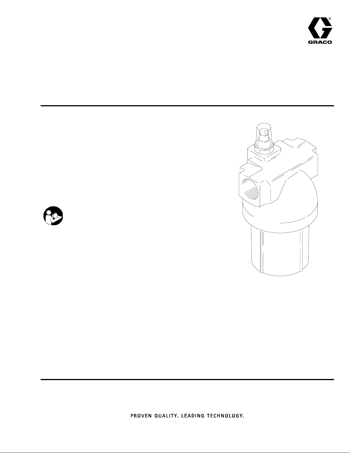
LOW PRESSURE, MEDIUM VOLUME
“red alert” Filters
Filters fluids and indicates when filter requires cleaning.
300 psi (21 bar) Maximum Working Pressure
6 gpm (22 liter/min) Flow Capacity
36 sq. in. (230 cm2) Filtering Area
Model No. 213057, 30 mesh (590 micron) element
Model No. 213058, 60 mesh (250 micron) element
Model No. 213059, 100 mesh (149 micron) element
Model No. 213060, 150 mesh (95 micron) element
Model No. 213061, 200 mesh (74 micron) element
Model No. 214001, without element
Important Safety Instructions
Read all warnings and instructions in this manual.
Save these instructions.
307282G
03708
Page 2
Installation
To clean or service the filter without shutting down the
system, install a dual filter or a filter bypass system as
explained below.
The numbers and letters in parentheses refer to Figs.
1, 2, and 3 and the Parts Drawing. Accessories and
Technical Data are on the front page.
NOTE: Allow 3 in. (76 mm) minimum clearance below
the filter for easy removal of the bowl (9).
Fluid Drain Valve (required in all systems)
WARNING
A fluid drain valve is required in the base of each
fluid filter. Use this drain valve to relieve fluid pressure in the filter, to reduce the risk of serious injury,
including fluid injection and splashing in the eyes or
on the skin.
Remove the 1/4 npt plug from the bottom of the filter
and install an adapter and drain valve (A,B). See
Fig. 1.
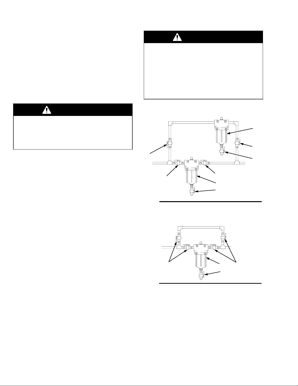
Dual Filter System
This setup enables you to redirect the fluid to another
filter while one filter is cleaned or serviced.
Install two filters as shown in Fig. 1. Install four suitable shutoff valves (D), one at each filter and outlet, to
redirect the fluid and isolate the filter not in use.
WARNING
To reduce the risk of component rupture and
serious bodily injury, do not exceed 300 psi (21
bar) Maximum Working Pressure, or the maximum
working pressure of the lowest rated component or
accessory in your system.
Be sure all components and accessories are rated
to withstand the maximum working pressure of
your pump.
D
D
Fig. 1
D
9
A,B
9
D
A,
B
03709
Filter Bypass System
This setup enables you to redirect the fluid through
pipes which bypass the filter while cleaning or servicing the filter.
Install the filter and bypass pipes as shown in Fig. 2.
Install four suitable shutoff valves (D), one each at the
filter inlet, the filter outlet, the bypass pipe inlet, and
the bypass pipe outlet. These valves redirect the fluid
and isolate the filter while cleaning and servicing.
Fig. 2
DD9
A,B
03710
2 307282
Page 3

Service
CAUTION
If the filter will not be used for a while, thoroughly
clean all the parts in solvent and blow them dry
before the paint dries and clogs the filter. To help
prevent damaging the parts, do not clean them with
a wire brush or sharp object.
Holding the bowl with a wrench to keep it from turning,
screw the drain plug (10) out. After the fluid has
drained out, remove the bowl, element and spring.
Replace immediately with the spare bowl, element and
spring to keep the paint from drying on the housing (3)
and other parts. Install the element with the dome end
up. Lubricate the threads of the bowl before screwing it
into the housing. Tighten it securely.
Indicator
The indicator provides gradual warning of a dirty
element. When the indicator shows 3/4 red, clean the
element. If not cleaned promptly, the filter bypass valve
opens and fluid will not be filtered.
Replace the indicator assembly (1) if the indicator is
not working correctly (it is always red or never red).
See Fig. 3.
To convert to a CV75 o-ring for special applications/
fluid compatibility, unscrew the indicator (1), remove
the existing o-ring (1a), and replace with 551981 o-ring
(must be ordered separately).
Bypass Valve
The valve opens when a dirty element causes the
filter’s outlet pressure to drop 15 psi (1 bar) below the
inlet pressure. This keeps the system pressure steady
and prevents the element from collapsing.
Replace the bypass valve (2) if it is damaged or worn.
Valve O-Ring
Clean the bowl, element and spring you removed with
a compatible solvent before the paint dries. Do not use
a wire brush or sharp object to clean. Store until
needed.
NOTE: Clean the filter element (7) with a small paint
brush. Blow out lodged particles with air, and inspect
for damage. Replace if ruptured.
3/4” npt(f) Inlet and outlet
1
2
1/4 npt(f) drain port
1
1a
2
1
3
6
The o-ring seals the bowl (9) to the housing (3). If material
leaks around the bowl, replace the o-ring (6).
Remove the bowl and o-ring. Clean the parts in a
compatible solvent. Be careful not to damage the
o-ring or sealing surfaces of the bowl and housing.
Before assembling, lubricate the parts with No. 2
grease.
Bowl, Element and Spring
To reduce downtime, keep a spare bowl (9), element
(7) and spring (8) on hand. Before removing the bowl,
direct the fluid through the bypass pipes or shut down
the system. Relieve fluid pressure by opening the drain
valve (B).
03707
Fig. 3
7
8
9
10
2
3307282
Page 4

Parts
Model No. 213057 to 213061
Includes items 1 to 10.
Model No. 214001
Includes items 1 to 6, 8 to 10;
Order the filter element separately from
those listed under Ref. No. 7.
Ref.
No. Part No. Description Qty.
1 104125 INDICATOR, filter (includes 1a) 1
1a O-RING, fluoroelastomer 1
See Accessories for CV75 o-ring
2 104440 VALVE, bypass 1
3n 172699 HOUSING, filter 1
6n 103209 O-RING, fluoroelastomer 1
See Accessories for PTFE o-ring
7n 108106 ELEMENT, filter,
30 mesh (590 micron
(for Model 213057 only) 1
108107 ELEMENT, filter,
60 mesh (250 micron)
(for Model 213058 only) 1
108108 ELEMENT, filter
100 mesh (149 micron)
(for Model 213059 only) 1
108109 ELEMENT, filter,
150 mesh (95 micron)
(for Model 213060 only) 1
108110 ELEMENT, filter,
200 mesh (74 micron)
(for Model 213061 only) 1
8n 102859 SPRING, element 1
9n 172725 BOWL, filter 1
10 100509 PLUG, pipe; 1/4 npt 1
n Keep these spare parts on hand to reduce downtime.
,
3/4” npt(f) Inlet and outlet
1
2
1/4 npt(f) drain port
1
1a
2
1
3
6
7
8
9
2
10
03707
4 307282
Page 5

Accessories
CV75 Indicator O-Ring 116768
For use with materials not compatible with the standard fluoroelastomer indicator o-ring
PTFE Housing O-Ring 102857
For use with materials not compatible with the standard fluoroelastomer o-ring
Drain Valve 208392
500 psi (34) Maximum Working Pressure
1/4 npt(m) x 3/8 npt(f). PTFE seal.
For relieving fluid pressure in the filter.
Technical Data
Maximum Working Pressure 300 psi (22 bar). . . . . . . .
Flow Capacity 6 gpm (22 liters/min). . . . . . . . . . . . . . . . .
Filter Area 36 sq. in. (232 cm2). . . . . . . . . . . . . . . . . . . . .
Wetted Parts Anodized Aluminum,R;. . . . . . . . . . . . . .
300 Series Stainless Steel,
PTFE, Plated Steel
Dimensions 4” (100 mm) width. . . . . . . . . . . . . . . . . . . . .
3.75” (95 mm) depth
8.75” (220 mm) height
Weight 3 lb (1.4 kg). . . . . . . . . . . . . . . . . . . . . . . . . . . . . .
5307282
Page 6

The Graco Standard Warranty
Graco warrants all equipment manufactured by Graco and bearing its name to be free from defects in material and workmanship on the
date of sale to the original purchaser for use. With the exception of any special, extended, or limited warranty published by Graco,
Graco will, for a period of twelve months from the date of sale, repair or replace any part of the equipment determined by Graco to be
defective. This warranty applies only when the equipment is installed, operated and maintained in accordance with Graco’s written
recommendations.
This warranty does not cover, and Graco shall not be liable for general wear and tear, or any malfunction, damage or wear caused by
faulty installation, misapplication, abrasion, corrosion, inadequate or improper maintenance, negligence, accident, tampering, or substitution of non–Graco component parts. Nor shall Graco be liable for malfunction, damage or wear caused by the incompatibility of
Graco equipment with structures, accessories, equipment or materials not supplied by Graco, or the improper design, manufacture,
installation, operation or maintenance of structures, accessories, equipment or materials not supplied by Graco.
This warranty is conditioned upon the prepaid return of the equipment claimed to be defective to an authorized Graco distributor for
verification of the claimed defect. If the claimed defect is verified, Graco will repair or replace free of charge any defective parts. The
equipment will be returned to the original purchaser transportation prepaid. If inspection of the equipment does not disclose any defect
in material or workmanship, repairs will be made at a reasonable charge, which charges may include the costs of parts, labor, and
transportation.
THIS WARRANTY IS EXCLUSIVE, AND IS IN LIEU OF ANY OTHER WARRANTIES, EXPRESS OR IMPLIED, INCLUDING BUT
NOT LIMITED TO WARRANTY OF MERCHANTABILITY OR WARRANTY OF FITNESS FOR A PARTICULAR PURPOSE.
Graco’s sole obligation and buyer’s sole remedy for any breach of warranty shall be as set forth above. The buyer agrees that no other
remedy (including, but not limited to, incidental or consequential damages for lost profits, lost sales, injury to person or property, or any
other incidental or consequential loss) shall be available. Any action for breach of warranty must be brought within two (2) years of the
date of sale.
Graco makes no warranty, and disclaims all implied warranties of merchantability and fitness for a particular purpose in connection
with accessories, equipment, materials or components sold but not manufactured by Graco. These items sold, but not manufactured
by Graco (such as electric motors, switches, hose, etc.), are subject to the warranty, if any, of their manufacturer. Graco will provide
purchaser with reasonable assistance in making any claim for breach of these warranties.
In no event will Graco be liable for indirect, incidental, special or consequential damages resulting from Graco supplying equipment
hereunder, or the furnishing, performance, or use of any products or other goods sold hereto, whether due to a breach of contract,
breach of warranty, the negligence of Graco, or otherwise.
FOR GRACO CANADA CUSTOMERS
The parties acknowledge that they have required that the present document, as well as all documents, notices and legal proceedings
entered into, given or instituted pursuant hereto or relating directly or indirectly hereto, be drawn up in English. Les parties reconnaissent avoir convenu que la rédaction du présente document sera en Anglais, ainsi que tous documents, avis et procédures judiciaires
exécutés, donnés ou intentés à la suite de ou en rapport, directement ou indirectement, avec les procedures concernées.
Graco Phone Number
TO PLACE AN ORDER, contact your Graco distributor, or call one of the following numbers
to identify the distributor closest to you:
1–800–328–0211 Toll Free
612–623–6921
612–378–3505 Fax
All written and visual data contained in this document reflects the latest product information available at the time of publication.
Graco reserves the right to make changes at any time without notice.
6 307282
This manual contains English. MM 307282
Graco Headquarters: Minneapolis
International Offices: Belgium, China, Japan, Korea
GRACO INC. P.O. BOX 1441 MINNEAPOLIS, MN 55440–1441
Copyright 1977, Graco Inc. is registered to ISO 9001
www.graco.com
Revised 2/2009
 Loading...