

Page 1
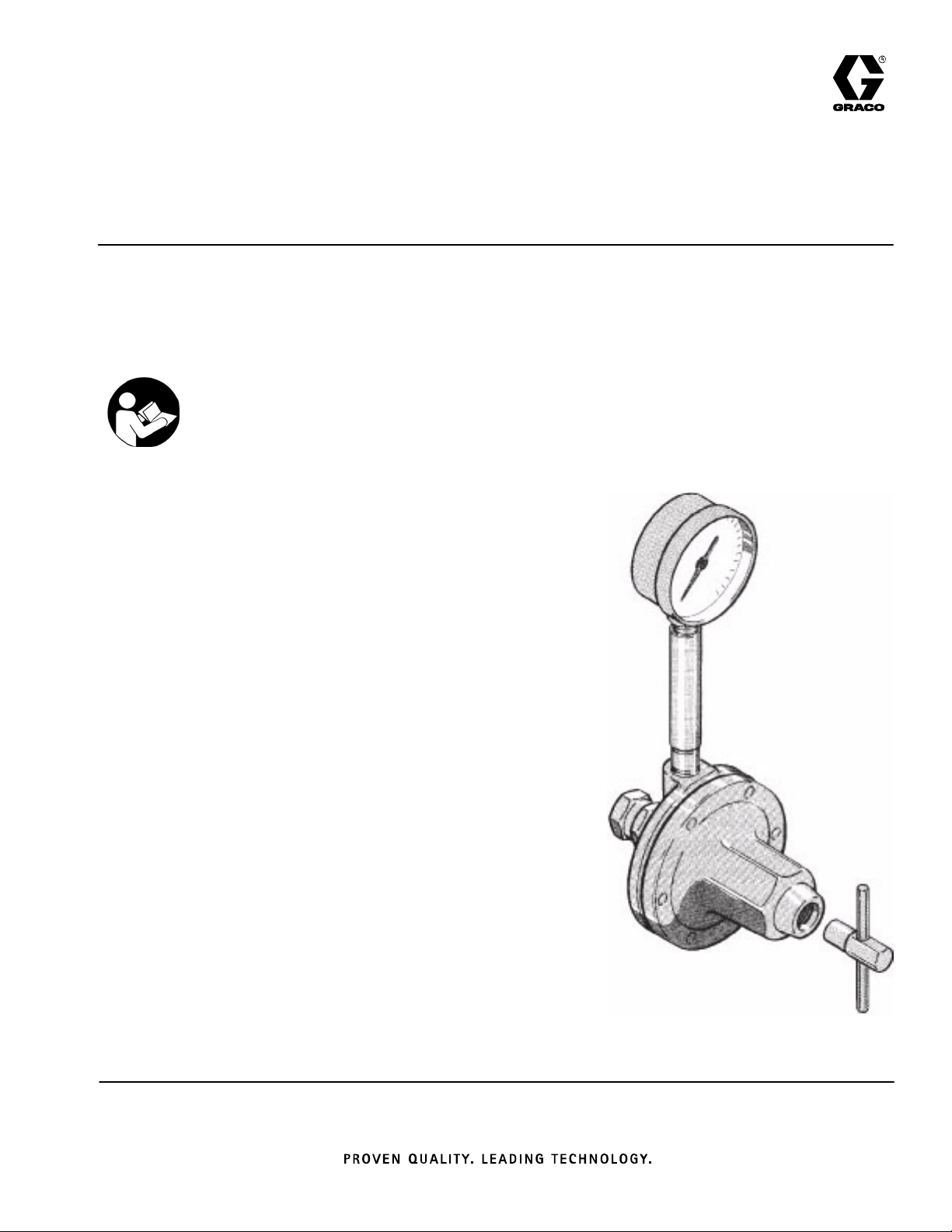
Instructions–Parts List
STAINLESS STEEL, WATERBASE COMPATIBLE
Fluid Pressure Regulators
Used to regulate fluid pressure in low pressure systems only.
Fluid Flow up to 3 GPM (11 liters/min)
Important Safety Instructions
Read all warnings and instructions in this manual.
Save these instructions.
See page 2 for Table of Contents. See page 3 for
List of Models.
307212ZAC
EN
Page 2

Table of Contents
Models 3. . . . . . . . . . . . . . . . . . . . . . . . . . . . . . . . . . . . . . . .
Warnings 5. . . . . . . . . . . . . . . . . . . . . . . . . . . . . . . . . . . . . .
Installation 6. . . . . . . . . . . . . . . . . . . . . . . . . . . . . . . . . . . . .
Operation 8. . . . . . . . . . . . . . . . . . . . . . . . . . . . . . . . . . . . .
Troubleshooting 11. . . . . . . . . . . . . . . . . . . . . . . . . . . . . . .
Service 12. . . . . . . . . . . . . . . . . . . . . . . . . . . . . . . . . . . . . .
Parts 16. . . . . . . . . . . . . . . . . . . . . . . . . . . . . . . . . . . . . . . .
Dimensions 21. . . . . . . . . . . . . . . . . . . . . . . . . . . . . . . . . . .
Technical Data 22. . . . . . . . . . . . . . . . . . . . . . . . . . . . . . . .
Performance Charts 23. . . . . . . . . . . . . . . . . . . . . . . . . . .
Warranty 24. . . . . . . . . . . . . . . . . . . . . . . . . . . . . . . . . . . . .
Graco Information 24. . . . . . . . . . . . . . . . . . . . . . . . . . . . .
2 307212
Page 3
Spring Operated Fluid Regulators
Models
Part No. Series Maximum Fluid Inlet
Pressure, psi (kPa, bar)
214895 H 250 (1800, 18) 5–100 (34–700, 0.3–7) No n/a
214706 H 250 (1800, 18) 5–100 (34–700, 0.3–7) Yes (see 0–100 (0–700, 0–7)
24A082 A 250 (1800, 18) 5–100 (34–700, 0.3–7) Yes (see 0–100 (0–700, 0–7)
255374 B 250 (1800, 18) 5–100 (34–700, 0.3–7) Yes (see 0–200 (0–1400, 0–14)
217314 F 250 (1800, 18) 20–160 (140–1100, 1.4–11) Yes 0–300 (0–2100, 0–21)
221118 E 250 (1800, 18) 20–160 (140–1100, 1.4–11) No n/a
ISO pitch thread inlet and outlet. Not compatible with US standard pitch.
Fluid housing coated with PTFE polymer.
Regulated Pressure
Range, psi (kPa, bar)
Gauge Gauge Pressure
Range,
psi (kPa, bar)
below)
below)
below)
These models are and certified.
The fluid supply system’s main line pressures often exceed the pressure range of the gauge supplied
with regulators 214706, 255374, and 24A082. Exposing this gauge to excessive pressure can damage
the gauge, causing inaccurate readings and the needle will not return to zero.
This damage is not covered by the Graco warranty.
Air Operated Fluid Regulators
Part No. Series Maximum
Regulated
Air Pressure,
psi (kPa, bar)
214980 F 30 (210, 2.1) 250 (1800, 18) 0–30 (0–210, 0–2.1) Yes 0–30 (0–210, 0–2.1)
244375 B 100 (700, 7) 250 (1800, 18) 5–100 (34–700, 0.3–7) No n/a
Regulated air pressures from 30–100 psi (210–690 kPa, 2.1–6.9 bar) may be used if a 100 psi rated gauge is
installed.
Maximum Fluid
Inlet Pressure,
psi (kPa, bar)
Regulated Pressure
Range,
psi (kPa, bar)
Gauge Gauge Pressure
Range,
psi (kPa, bar)
3307212
Page 4

Notes
4 307212
Page 5
WARNING
PRESSURIZED EQUIPMENT HAZARD
Spray from the gun, hose leaks, or ruptured components can splash fluid in the eyes or on the skin
and cause serious injury.
Do not stop or deflect fluid leaks with your hand, body, glove, or rag.
Follow the Pressure Relief Procedure on page 8 whenever you: are instructed to relieve the
pressure; stop spraying; clean, check, or service the equipment; and install or clean the fluid
nozzle.
Tighten all the fluid connections before operating the equipment.
Check the hoses, tubes, and couplings daily. Replace worn, damaged, or loose parts immediately.
Permanently coupled hoses cannot be repaired; replace the entire hose.
EQUIPMENT MISUSE HAZARD
INSTRUCTIONS
Equipment misuse can cause the equipment to rupture, malfunction, or start unexpectedly and result
in a serious injury.
This equipment is for professional use only.
Read all the instruction manuals, tags, and labels before operating the equipment.
Use the equipment only for its intended purpose. If you are uncertain about usage, call your Graco
distributor.
Do not alter or modify this equipment. Use only genuine Graco parts and accessories.
Check the equipment daily. Repair or replace worn or damaged parts immediately.
Do not exceed the maximum working pressure of the lowest rated system component.
Use fluids that are compatible with the equipment wetted parts. See the Technical Data section of
all the equipment manuals. Read the fluid manufacturer’s warnings.
Never use 1,1,1–trichloroethane, methylene chloride, other halogenated hydrocarbon solvents, or
fluids containing such solvents in these regulators. In the event that there is a diaphragm failure, a
serious chemical reaction could occur, with the possibility of explosion.
Route the hoses away from traffic areas, sharp edges, moving parts, and hot surfaces. Do not
expose Graco hoses to temperatures above 180F (82C) or below –40F (–40C).
Never kink or over bend the hoses or use the hoses to pull equipment.
Comply with all applicable local, state, and national fire, electrical, and other safety
regulations.
5307212
Page 6
Installation
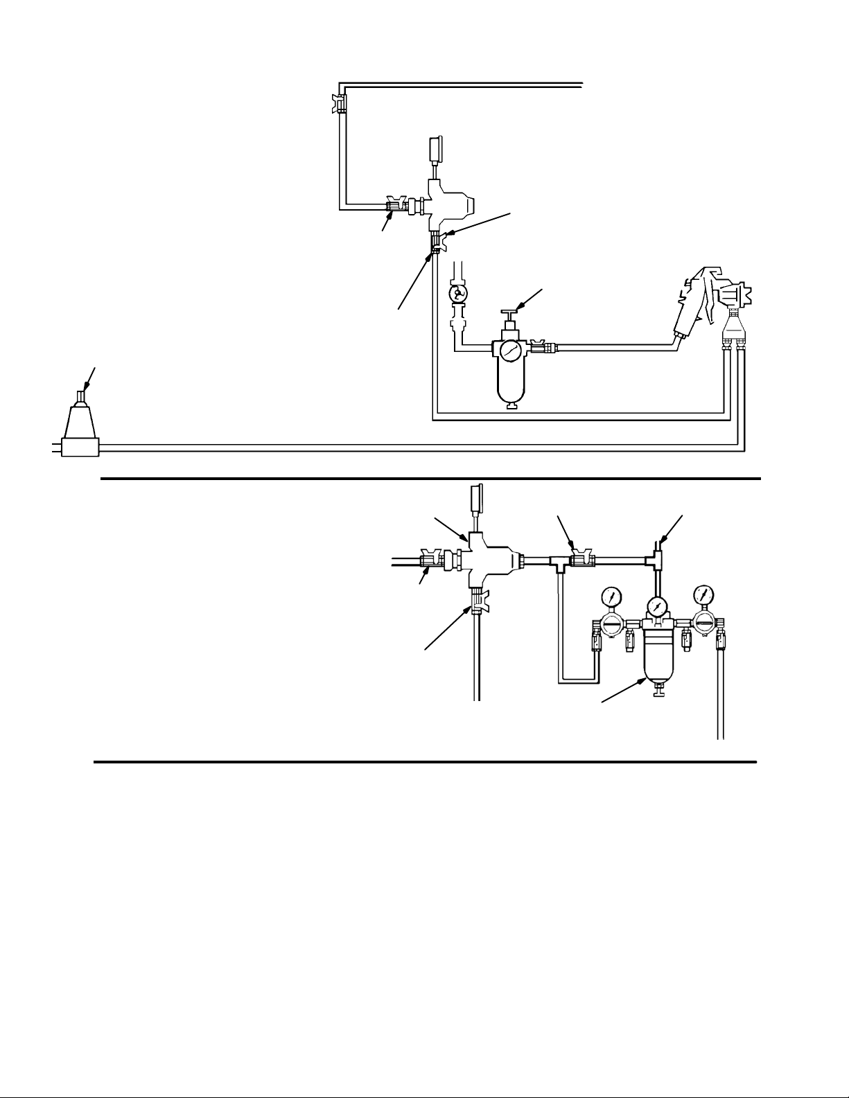
Spring Operated Installation
Models 214895, 214706, 217314,
221118, 255374, and 24A082
BACK
PRESSURE
VALV E
FLUID RETURN
Fig. 1
Pilot Regulator Air Supply Line
Air Operated Installation
Model 214980 shown
INLET BALL VALVE
PIPE NIPPLES
FLUID REGULATOR
FLUID SUPPLY
OUTLET BALL VALVE
AIR FILTER
& REGULATOR
AIR REGULATOR
BYPASS VALVE
AIR SUPPLY
Fig. 2
INLET BALL VALVE
OUTLET BALL VALVE
AIR FILTER
MOISTURE SEPARATOR
& REGULATORS
6 307212
Page 7

Installation
Fluid pressure regulators are used for accurate, positive control of the fluid pressure to spray guns, dispensing valves or atomizing heads.
Regulators installed at circulating line take-offs or
pumps are used to reduce main line pressure and
maintain the desired fluid pressure to the spray gun or
atomizing head.
Before Installing the Fluid Regulator
1. Determine where to locate the regulator.
2. Install a ball valve for the regulator inlet and outlet.
3. Install temporary plumbing between the ball
valves.
4. Thoroughly flush the system to remove metal
chips and other contaminants and to check for
leaks.
Installing the Fluid Regulator
1. Remove the temporary plumbing and install one
regulator for each spray gun. See the Dimension-
al Drawing on page 21 for regulator dimensions.
Mount the regulator in a vertical position, as shown
in Figs. 1 and 2, for the best flow and minimum
pigment settling. The gauge, if used, must be
mounted vertically. If the regulator is mounted
horizontally, an elbow must be used so the gauge
will be vertical.
2. Put sealer on threaded connections, except on the
swiveling end of swivel unions as it interferes with
the swivel action.
3. Flush and test the entire system. Be sure to follow
the flushing procedure on page 8.
7307212
Page 8
Operation
CAUTION
The new system must be cleaned and tested
thoroughly before admitting fluid to the regulator
to avoid contaminants clogging or damaging the
regulator.
Always use the lowest possible air and fluid
pressures for your application. High pressures
cause premature spray nozzle and pump wear.
NOTE: Reference numbers and letters in parentheses
in the text refer to the Figs. and Parts Drawing.
Pressure Relief Procedure
WARNING
PRESSURIZED EQUIPMENT HAZARD
Read warnings, page 5.
1. Shut off the pump.
2. Shut off the pump and relieve fluid pressure in the
system by triggering the gun and opening the back
pressure regulator or other bypass valve.
3. Never exceed the maximum working pressure of
the lowest rated system component. Remove the
gauge if the flushing pressure will exceed the
gauge range.
4. Open the fluid regulator fully.
a. Spring Operated Regulators Only (see Fig. 3).
The regulator can be fully opened in two ways:
Using the male end (B) of the regulator
key (24), turn the socket–head adjustment
screw (19) fully counterclockwise. The
pressure setting will be retained.
Using the female end (A) of the regulator
key (24), turn the adjustment screw (12)
fully clockwise. You will have to reset
pressure after flushing.
2. Close the fluid regulator’s inlet ball valve. Refer to
Figs. 1 and 2.
3. Relieve fluid pressure in the fluid regulator by
triggering the spray gun.
Flushing Procedure
Flush before changing colors, before fluid can dry in
the equipment, at the end of the day, before storing,
and before repairing equipment.
Flush at the lowest pressure possible. Check
connectors for leaks and tighten as necessary.
Flush with a fluid that is compatible with the fluid
being dispensed and the equipment wetted parts.
1. Record the pressure adjustment setting of the fluid
regulator before flushing.
b. Air Operated Regulator Only. The regulator
can be fully opened in two ways:
Close the outlet valve at the air regulator
and open the air regulator bypass valve, to
supply air directly to the fluid regulator; do
not exceed the maximum rated air pressure of the fluid regulator. Pressure setting
of the fluid regulator will be retained using
this method.
Increase the air regulator setting to fully
open the fluid regulator. You will have to
reset the fluid regulator’s pressure setting
after flushing.
5. Supply solvent to the system. Set pump to the
lowest possible pressure, and start pump.
6. Flush until thoroughly clean.
8 307212
Page 9

Operation
7. Adjust the fluid regulator to the desired setting.
a. Spring Operated Regulators Only (see Fig. 3).
The regulator can be adjusted in two ways:
Using the male end (B) of the regulator
key (24), turn the socket–head adjustment
screw (19) fully clockwise. Verify that the
pressure setting has not changed.
Using the female end (A) of the regulator
key (24), turn the adjustment screw (12)
counterclockwise to return to the desired
pressure setting.
b. Air Operated Regulator Only. The regulator
can be adjusted in two ways:
Close the air regulator bypass valve and
open the outlet valve at the air regulator.
Verify that the pressure setting has not
changed.
Adjust the air regulator to return to the
desired fluid pressure setting.
NOTE: If using a fluid pressure gauge, reduce the
regulator pressure before partially relieving pressure in
the gun hose, to ensure a correct gauge reading. Then
increase regulator pressure to the desired setting.
Air Operated Regulator
1. Start the pump and open the fluid regulator’s inlet
ball valve to admit fluid to the regulator. See Fig. 2.
2. Increase the air pressure to obtain the desired fluid
pressure. Adjust for the desired spray pattern.
NOTE: If using a fluid pressure gauge, reduce the
regulator pressure before partially relieving pressure in
the gun hose, to ensure a correct gauge reading. Then
increase regulator pressure to the desired setting.
NOTE: Make sure the air bleed hole in the air line
fitting (29) is not plugged. Refer to page 12.
For the best results, use an air regulator with at least a
2 in. (51 mm) diameter diaphragm to control this fluid
regulator.
Regulating Fluid Pressure
Spring Operated Regulator
1. Close the regulator: engage the female end (A) of
the key (24) with the adjusting screw (12) and turn
it counterclockwise to relieve the spring tension.
See Fig. 3.
2. Start the pump and open the fluid regulator’s inlet
ball valve to admit fluid to the regulator. See Fig. 1.
3. Turn the key (24) clockwise to increase fluid pressure. See Fig. 3. Adjust for the desired spray
pattern.
12
B
A
24
Fig. 3
9307212
Page 10

Notes
10 307212
Page 11

Troubleshooting
WARNING
To reduce the risk of serious injury whenever you
are instructed to relieve pressure, always follow the
Pressure Relief Procedure on page 8.
Before servicing this equipment always make sure to
Relieve the Pressure.
Check all possible remedies in the Troubleshooting
Chart before disassembling the fluid regulator.
Problem
No pressure regulation
Fluid leaks from under cap
Pressure creeps above setting
Pressure drops below setting
Cause Solution
Damaged or clogged air regulator or
line (214980 only)
Damaged diaphragm (22) Replace diaphragm.
Loose cap (7) Tighten screws (1) in sequence
Worn gasket (26) Replace gasket.
Damaged or clogged air regulator or
line (214980 only)
Damaged diaphragm (22) Replace diaphragm.
Seat leaking (16) Replace ball (20), seat, and gasket
Damaged or clogged air regulator or
line (214980 only)
Empty/clogged supply line Fill/flush supply line.
Clogged air spray gun or fluid dis-
pensing valve.
Using regulator beyond its rated flow
capacity, see the Technical Data on
Page 22.
Clear obstruction in line, service regulator if necessary.
shown in Service section.
Clear obstruction in line, service regulator if necessary.
(15).
Clear obstruction in line, service regu-
lator if necessary.
Replace, see gun or valve manual for
service instructions.
Install additional regulators.
11307212
Page 12

Service
Service of the Air Operated Regulators
WARNING
To reduce the risk of serious injury whenever you
are instructed to relieve pressure, always follow the
Pressure Relief Procedure on page 8.
1. Shut off the pump.
2. Close the ball valve at the regulator’s air inlet.
Refer to Fig. 2.
3. Release all the air and fluid pressure in the regulator and disconnect the air and fluid lines.
4. Remove the regulator from the system.
5. Remove the swivel union (23) and spring (40) from
the regulator body.
6. Remove the ball (20), seat (16), and gasket (15).
See Fig. 4.
CAUTION
Use special care when handling the hard carbide ball
(20) and seat (16) to avoid damaging them.
NOTE: Gasket (15) is thin and translucent. Be sure to
remove the gasket.
7. Remove the six cap screws (1) and housing (6).
8. Place diaphragm assembly in a vise, with jaws on
stem housing (18). Remove the retaining screw
(10), jam nut (13) and washer (17) from the stem
housing (18).
9. Remove the diaphragm (22) and gasket (26).
10. Remove the spring (3), valve stem (9), and gasket
(21) from the stem housing (18).
11. Thoroughly clean and inspect all parts. Replace
any parts that appear to be worn or damaged.
12. Place stem housing (18) in a vise. One at a time,
place the gasket (26), diaphragm (22) – white
PTFE side down toward the bottom housing, and
washer (17) on the stem housing (18). Secure
them with the jam nut (13). Torque the jam nut
onto the stem housing to 21–35 ft-lb (28–47 Nm).
13. Install the valve stem (9), spring (3), gasket (21),
and retaining screw (10) in the stem housing (18).
Make sure the tab on the valve stem (9) fits into
the slot on screw (10).
14. Torque the retaining screw into the housing to
21–25 ft-lb (28–34 Nm).
15. Install the assembled parts in the housing (6).
16. On Model 214980, tighten the air line fitting (29)
into the cap (7). Torque to 21–35 ft-lb (28–47
Nm).
17. Install the cap (7). Tighten the six cap screws (1) in
the sequence shown in Fig. 4, Bottom View, and
to the torque noted.
18. Install the gasket (15), valve seat (16), and ball
(20) into the housing (6).
NOTE: Seat may be turned upside down and reused.
19. Screw the swivel union (23), with the o-ring (4)
attached and the spring (40) in place, into the inlet.
Torque to 23–27 ft-lb (31–36 Nm).
12 307212
Page 13

Service
Models 214980 (shown) & 244375
29
1
Air Bleed Hole
10
2
13
1
1
Torque to 21–35 ft-lb (28–47 Nm)
2
Torque to 21–25 ft-lb (28–34 Nm)
3
Torque to 23–27 ft-lb (31–36 Nm)
7
1
17
22
NOTE: Numbers indicate tightening sequence.
Tighten evenly to 7–10 in-lb (0.8–1.1 Nm), then
retorque to 125 in-lb (14 Nm) three times, consecutively, to compensate for diaphragm relaxation.
26
18
BOTTOM VIEW
3
5
2
9
15
16
23
4
20
3
1
6
4
6
Fig. 4
21
3
40
13307212
Page 14

Service
Service of the Spring Operated Regulators
WARNING
To reduce the risk of serious injury whenever you
are instructed to relieve pressure, always follow the
Pressure Relief Procedure on page 8.
1. Shut off the pump.
2. Close the ball valve at the regulator’s fluid inlet.
See Fig. 1.
3. Release all fluid pressure in the regulator and
disconnect the fluid line.
4. Remove the regulator from the system.
5. Remove the swivel union (23) and spring (40) from
the regulator body.
6. Remove the ball (20), valve seat (16), and gasket
(15). See Fig. 5.
CAUTION
Use special care when handling the hard carbide ball
(20) and seat (16) to avoid damaging them.
10. Remove the diaphragm (25) – on Models 217314
and 221118 only, diaphragm (22), and gasket (26).
11. Remove the spring (3), valve stem (9) and gasket
(21) from the stem housing.
12. Thoroughly clean and inspect all parts. Replace
any parts that appear to be worn or damaged.
13. Place stem housing (18) in a vise. One at a time,
place the gasket (26), diaphragm (22) – white
PTFE side down toward bottom housing, diaphragm (25) – on Models 217314 and 221118 only,
and washer (17) on the stem housing (18). Secure
them with the jam nut (13).
NOTE: On Models 217314 and 221118, align the
holes on the diaphragms (25 & 22) before tightening
the jam nut (13).
14. Torque the jam nut (13) onto the stem housing (18)
to 21–35 ft-lb (28–47 Nm).
15. Install the valve stem (9), spring (3), gasket (21)
and retaining screw (10) in the stem housing (18).
Make sure the tab on the valve stem (9) fits into
the slot on screw (10).
16. Torque the retaining screw (10) into the housing to
21–25 ft-lb (28–34 Nm).
NOTE: Gasket (15) is thin and translucent. Be sure to
remove the gasket.
7. Remove the six cap screws (1) and housing (6).
8. Remove the cap (7), adjusting screw (12) and
spring (5).
9. Place diaphragm assembly in a vise, with jaws on
stem housing (18). Remove the stem retaining
screw (10), jam nut (13), and washer (17) from the
stem housing (18).
17. Install the spring, adjusting screw (12) and cap on
the housing (6). Tighten six capscrews (1) in the
sequence shown in Fig. 5, Bottom View, and to
the torque noted.
18. Install the gasket (15), valve seat (16), and ball
(20) into the housing (6).
NOTE: Seat may be turned upside down and reused.
19. Screw the swivel union (23), with the o-ring (4)
attached and the spring (40) in place, into the inlet.
Torque to 23–27 ft-lb (31–36 Nm).
14 307212
Page 15

Models 217314
and 221118
7
1
5
18
9
6
4
20
40
Service
1
12
10
1
21
13
2
25
PET
22
4
17
26
3
15
16
23
3
Torque to 21–25 ft-lb (28–34 Nm)
Torque to 21–35 ft-lb (28–47 Nm)
2
Torque to 23–27 ft-lb (31–36 Nm)
3
PTFE side down toward housing (6)
4
Models 214895, 214706,
255374, and 24A082
12
10
1
NOTE: Numbers indicate tightening sequence. Tighten
evenly to 7–10 in-lb (0.8–1.1 Nm), then retorque
to 125 in-lb (14 Nm) three times, consecutively,
to compensate for diaphragm relaxation.
BOTTOM VIEW
3
1
5
2
4
6
Fig. 5
18
1
21
13
22
2
4
17
26
3
15
9
16
23
3
6
4
20
40
15307212
Page 16

Parts
Model 214895, Series H
Without gauge. Includes items 1–26, 40
Model 214706, Series H
With gauge. Includes items 1–40
14
12
11
*21
*3
*9
19
10
24
13
17
7
22*
26*
18
6
5
*15
*16
*20
1
40*
4*
23
28
Ref
No. Part No. Description Qty.
1 100644 SCREW, soc hd cap;
0.25”–20 x 0.75” 6
3 111736* SPRING, compression 1
4 104319* O-RING, PTFE 1
5 105291 SPRING, compression 1
6 187880 HOUSING; stainless steel 1
7 176135 CAP, regulator 1
9 187851* STEM, valve 1
10 188004 SCREW, retaining 1
11 171855 NUT, adjustment 1
12 176691 SCREW, adjustment 1
13 171858 NUT, jam; special 1
14 176692 WASHER, flat 1
15 171860* GASKET, seat 1
16 112366* SEAT, valve; tungsten carbide 1
15F236 SEAT, valve; tungsten carbide 1
17 171862 WASHER, diaphragm 1
18 187879 HOUSING, stem 1
27
Ref.
No. Part No. Description Qty.
19 176136 SCREW, adjustment 1
20 112365* BALL; tungsten carbide 1
21 171867* GASKET 1
22 171868* DIAPHRAGM; PTFE with nylon
23 235209 UNION, swivel; 3/8 npsm 1
24 215393 KEY, regulator 1
26 172132* GASKET; cellulose fibre 1
27 187874 GAUGE, pressure; stainless steel;
28 187877 TUBE, riser
40 111858* SPRING, compression 1
* Included in Repair Kit 222651.
Included in Repair Kit 249147 (for solvent or thin material).
Model 214706 only
fabric/Buna-N base 1
100 psi (0.7 MPa, 7 bar)
(214706 only) 1
(214706 only) 1
16 307212
Page 17

Parts
Model 255374, Series A
Model 24A082, Series A
ISO pitch thread inlet and outlet
(not compatible with US standard pitch –
fluid housing coated with PTFE based
polymer)
Includes items 1–40
19
14
12
11
10
*21
*3
24
13
17
7
22*
26*
18
6
5
*15
*16
*20
1
40*
4*
23
*9
Ref
No. Part No. Description Qty.
1 100644 SCREW, soc hd cap;
0.25”–20 x 0.75” 6
3 111736* SPRING, compression 1
4 104319* O-RING, PTFE 1
5 105291 SPRING, compression 1
6 195935 HOUSING; stainless steel w/PTFE
coating 3/8–19, ISO female outlet 1
7 176135 CAP, regulator 1
9 187851* STEM, valve 1
10 188004 SCREW, retaining 1
11 171855 NUT, adjustment 1
12 176691 SCREW, adjustment 1
13 171858 NUT, jam; special 1
14 176692 WASHER, flat 1
15 171860* GASKET, seat 1
16 15F236* SEAT, valve; tungsten carbide
(24A082 only) 1
15V292 SEAT, valve; tungsten carbide
(255374 only) 1
17 171862 WASHER, diaphragm 1
27
TI0037
Ref.
No. Part No. Description Qty.
18 187879 HOUSING, stem 1
19 176136 SCREW, adjustment 1
20 112365* BALL; tungsten carbide 1
21 171867* GASKET 1
22 171868 DIAPHRAGM; PTFE with nylon
fabric/Buna-N base 1
23 195934 ADAPTER, inlet; 3/8–19, ISO
male inlet 1
24 215393 KEY, regulator 1
26 172132* GASKET; cellulose fibre 1
27 187873 GAUGE, pressure; stainless steel;
200 psi (1.4 MPa, 14 bar);
(255374 only) 1
187874 GAUGE, pressure; stainless steel;
100 psi (0.7 MPa, 7 bar);
(24A082 only) 1
40 111858* SPRING, compression 1
* Included in Repair Kit 222651.
Included in Repair Kit 273024 (for solvent or thin material).
17307212
Page 18

Parts
Model 217314, Series F
With gauge. Includes items 1–32, 40
Model 221118, Series E
Without gauge. Includes items
1–26, 32–40
14
12
11
*21
*3
*9
19
10
24
13
17
7
25*
22*
26*
18
32
Model
221118 only
39
6
5
*15
*16
*20
40*
1
4*
23
28
Ref
No. Part No. Description Qty.
1 100644 SCREW, soc hd cap;
0.25”–20 x 0.75” 6
3 111736* SPRING, compression 1
4 104319* O-RING, PTFE 1
5 106480 SPRING, compression 1
6 187880 HOUSING; stainless steel 1
7 176135 CAP, regulator 1
9 187851* STEM, valve 1
10 188004 SCREW, retaining 1
11 171855 NUT, adjustment 1
12 176691 SCREW, adjustment 1
13 171858 NUT, jam; special 1
14 176692 WASHER, flat 1
15 171860* GASKET, seat 1
16 112366* SEAT, valve; tungsten carbide 1
15F236 SEAT, valve; tungsten carbide 1
17 171862 WASHER, diaphragm 1
18 187879 HOUSING, stem 1
19 176136 SCREW, adjustment 1
27
Ref.
No. Part No. Description Qty.
20 112365* BALL; tungsten carbide 1
21 171867* GASKET 1
22 180052* DIAPHRAGM; PTFE 1
23 235209 UNION, swivel; 3/8 npsm 1
24 215393 KEY, regulator 1
25 180051* DIAPHRAGM, PET 1
26 172132* GASKET; cellulose fibre 1
27 187876 GAUGE, pressure; stainless steel;
28 187877 TUBE, riser (217314 only) 1
32 235207 ADAPTER, straight union; 3/8 npsm 1
39 111697 PLUG, pipe; 1/4 npt(m);
40 111858* SPRING, compression 1
* Included in Repair Kit 222652.
Included in Repair Kit 249148 (for solvent or thin material).
Model
217314 only
300 psi (2.1 MPa, 21 bar)
(217314 only) 1
(221118 only) 1
18 307212
Page 19

Model 214980 Series F
Includes items 1–40
7
Parts
13
17
22*
26*
18
6
29
10
*21
*3
*9
Ref
No. Part No. Description Qty.
1 100644 SCREW, soc hd cap;
0.25”–20 x 0.75” 6
3 111736* SPRING, compression 1
4 104319* O-RING, PTFE 1
6 187880 HOUSING; stainless steel 1
7 176135 CAP, regulator 1
9 187851* STEM, valve 1
10 188004 SCREW, retaining 1
13 171858 NUT, jam; special 1
15 171860* GASKET, seat 1
16 112366* SEAT, valve; tungsten carbide 1
15F236 SEAT, valve; tungsten carbide 1
17 171862 WASHER, diaphragm 1
18 187879 HOUSING, stem 1
*15
*16
*20
1
40*
4*
28
23
27
Ref.
No. Part No. Description Qty.
20 112365* BALL; tungsten carbide 1
21 171867* GASKET 1
22 171868* DIAPHRAGM; PTFE with
nylon fabric/Buna-N base 1
23 235209 UNION, swivel; 3/8 npsm 1
26 172132* GASKET; cellulose fibre 1
27 187875 GAUGE, pressure; stainless steel;
30 psi (210 kPa, 2.1 bar) 1
28 187877 TUBE, riser 1
29 176463 FITTING, air line 1
40 111858* SPRING, compression 1
* Included in Repair Kit 222651.
Included in Repair Kit 249147 (for solvent or thin material).
19307212
Page 20

Model 244375 Series B
Includes items 1–41
7
29
10
Parts
26*
18
*22
13
17
*21
*3
*9
41
19
*15
*16
*20
6
1
40*
4*
23
TI1697A
Ref
No. Part No. Description Qty.
1 100644 SCREW, soc hd cap;
0.25”–20 x 0.75” 4
3 111736* SPRING, compression 1
4 104319* O-RING, PTFE 1
6 187880 HOUSING; stainless steel 1
7 833166 CAP, regulator 1
9 187851* STEM, valve 1
10 188004 SCREW, retaining 1
13 171858 NUT, jam; special 1
15 171860* GASKET, seat 1
16 112366* SEAT, valve; tungsten carbide 1
15F236 SEAT, valve; tungsten carbide 1
17 171862 WASHER, diaphragm 1
18 187879 HOUSING, stem 1
20 307212
Ref.
No. Part No. Description Qty.
19 197213 STUD, mounting 2
20 112365* BALL; tungsten carbide 1
21 171867* GASKET 1
22 171868* DIAPHRAGM; PTFE with
nylon fabric/Buna-N base 1
23 235209 UNION, swivel; 3/8 npsm 1
26 172132* GASKET; cellulose fibre 1
29 114151 FITTING, air line 1
40 111858* SPRING, compression 1
41 101748 PLUG, pipe 1
* Included in Repair Kit 222651.
Included in Repair Kit 249147 (for solvent or thin material).
Page 21

Dimensions
1.76” (44.7 mm)
1.8” (46 mm)
3/8 npsm female INLET
3.65” (93 mm) DIA.
3/8 npt(f) OUTLET
Model 244375: 3” (76.2 mm)
All Other Models: 4.94” (125.5 mm)
1/4 npt
GAUGE PORT
10.25”
(260 mm)
1/4 npt AIR INLET
(Model 214980 only)
3/8 npsm female ADAPTER OUTLET
(Models 217314 and 221118 only)
21307212
Page 22

Technical Data
Category Data
Maximum Fluid Inlet Pressure 250 psi (1.8 MPa, 18 bar)
Regulated Fluid Pressure Range Models 217314 & 221118: 20–160 psi (0.15–1.1 MPa, 1.5–11 bar)
Models 214706, 214895, 244375, 255374, & 24A082: 5–100 psi
(30–700 kPa, 0.3–7.0 bar)
Model 214980: 0–30 psi (0–210 kPa, 0–2 bar)
Maximum Flow Capacity 3 gpm (11 liters/min) with 70 cps fluid at 200 psi (1.4 MPa, 14 bar)
inbound pressure
Wetted Parts Tungsten Carbide, Acetal Resins, PTFE, 304 & 316 Series Stain-
less Steel, Nylon, PET.
Canadian Registration Number (CRN):
Alberta – 0C04874.52
Ontario – 0C4874.5R1
Models: 214895, 214706, 217314, 221118, and 214980
22 307212
Page 23

Performance Chart
MODELS 217314
and 221118
kPa bar psi
11.1
1110
980
910
840
770
700
620
550
480
410
345
280
210
140
70
10.4
9.8
9.1
8.4
7.7
7.0
6.2
5.5
4.8
4.1
3.4
2.8
2.1
1.4
0.7
1040
gpm
160
250 PSI INLET,
65 CPS
150
140
130
120
110
250 PSI INLET,
600 CPS
250 PSI INLET,
65 CPS
100
90
80
70
100 PSI INLET,
65 CPS
250 PSI INLET,
65 CPS
60
50
40
30
100 PSI INLET,
600 CPS
250 PSI INLET,
600 CPS
20
10
0
012345
MODELS
214706,
214895,
214980,
244375,
255374, and
24A082
liters/min
kPa bar psi
7.0
700
6.2
620
5.5
550
4.8
480
4.1
410
3.4
345
2.8
280
2.1
210
1.4
140
0.7
70
100
90
80
70
60
50
40
30
20
10
3.82 7.62 11.42 15.22 22.10
FLUID FLOW
100 PSI INLET,
600 CPS
100 PSI INLET,
600 CPS
100 PSI INLET,
65 CPS
250 PSI INLET,
600 CPS
100 PSI INLET,
65 CPS
250 PSI INLET,
65 CPS
250 PSI INLET,
600 CPS
250 PSI INLET,
65 CPS
gpm
liters/min
0
012345
3.82 7.62 11.42 15.22 22.10
FLUID FLOW
23307212
Page 24

Graco Standard Warranty
Graco warrants all equipment manufactured by Graco and bearing its name to be free from defects in material and workmanship on the
date of sale to the original purchaser for use. With the exception of any special, extended, or limited warranty published by Graco,
Graco will, for a period of twelve months from the date of sale, repair or replace any part of the equipment determined by Graco to be
defective. This warranty applies only when the equipment is installed, operated and maintained in accordance with Graco’s written
recommendations.
This warranty does not cover, and Graco shall not be liable for general wear and tear, or any malfunction, damage or wear caused by
faulty installation, misapplication, abrasion, corrosion, inadequate or improper maintenance, negligence, accident, tampering, or substitution of non–Graco component parts. Nor shall Graco be liable for malfunction, damage or wear caused by the incompatibility of
Graco equipment with structures, accessories, equipment or materials not supplied by Graco, or the improper design, manufacture,
installation, operation or maintenance of structures, accessories, equipment or materials not supplied by Graco.
This warranty is conditioned upon the prepaid return of the equipment claimed to be defective to an authorized Graco distributor for
verification of the claimed defect. If the claimed defect is verified, Graco will repair or replace free of charge any defective parts. The
equipment will be returned to the original purchaser transportation prepaid. If inspection of the equipment does not disclose any defect
in material or workmanship, repairs will be made at a reasonable charge, which charges may include the costs of parts, labor, and
transportation.
THIS WARRANTY IS EXCLUSIVE, AND IS IN LIEU OF ANY OTHER WARRANTIES, EXPRESS OR IMPLIED, INCLUDING BUT
NOT LIMITED TO WARRANTY OF MERCHANTABILITY OR WARRANTY OF FITNESS FOR A PARTICULAR PURPOSE.
Graco’s sole obligation and buyer’s sole remedy for any breach of warranty shall be as set forth above. The buyer agrees that no other
remedy (including, but not limited to, incidental or consequential damages for lost profits, lost sales, injury to person or property, or any
other incidental or consequential loss) shall be available. Any action for breach of warranty must be brought within two (2) years of the
date of sale.
Graco makes no warranty, and disclaims all implied warranties of merchantability and fitness for a particular purpose in connection
with accessories, equipment, materials or components sold but not manufactured by Graco. These items sold, but not manufactured
by Graco (such as electric motors, switches, hose, etc.), are subject to the warranty, if any, of their manufacturer. Graco will provide
purchaser with reasonable assistance in making any claim for breach of these warranties.
In no event will Graco be liable for indirect, incidental, special or consequential damages resulting from Graco supplying equipment
hereunder, or the furnishing, performance, or use of any products or other goods sold hereto, whether due to a breach of contract,
breach of warranty, the negligence of Graco, or otherwise.
FOR GRACO CANADA CUSTOMERS
The parties acknowledge that they have required that the present document, as well as all documents, notices and legal proceedings
entered into, given or instituted pursuant hereto or relating directly or indirectly hereto, be drawn up in English. Les parties reconnaissent avoir convenu que la rédaction du présente document sera en Anglais, ainsi que tous documents, avis et procédures judiciaires
exécutés, donnés ou intentés à la suite de ou en rapport, directement ou indirectement, avec les procedures concernées.
Graco Information
For the latest information about Graco products, visit www.graco.com. For patent information, see www.graco.com/
patents.
TO PLACE AN ORDER, contact your Graco distributor or call to identify the distributor closest to you:
Phone: 612–623–6921 or Toll Free: 1–800–328–0211 Fax: 612–378–3505
All written and visual data contained in this document reflects the latest product information available at the time of publication.
Graco reserves the right to make changes at any time without notice.
Original instructions. This manual contains English. MM 307212
24 307212
International Offices: Belgium, China, Japan, Korea
Graco Headquarters: Minneapolis
GRACO INC. AND SUBSIDIARIES S P.O. BOX 1441 S MINNEAPOLIS MN 55440–1441 S USA
Copyright 1975, Graco Inc. All Graco manufacturing locations are registered to ISO 9001.
www.graco.com
Revised October 2013
 Loading...