

Page 1
Instructions - Parts
Fluid Controls and
307016T
Fittings
Part No. 223627, 208085, 223621, 208082, 223622, 223623, 223624, 208250,
214019, 223626, and 210097
200 psi (1.4 MPa, 14 bar) Maximum Inbound Fluid Pressure
Part No. 223625 and 223628
300 psi (2.1 MPa, 21 bar) Maximum Inbound Fluid Pressure
See page 2 for model information
EN
Important Safety Instructions
Read all warnings and instructions in this
manual. Save these instructions.
ti02286a
Page 2
Contents
Warnings . . . . . . . . . . . . . . . . . . . . . . . . . . . . . . . . . 3
Installation . . . . . . . . . . . . . . . . . . . . . . . . . . . . . . . . 4
Operation . . . . . . . . . . . . . . . . . . . . . . . . . . . . . . . . . 4
Service . . . . . . . . . . . . . . . . . . . . . . . . . . . . . . . . . . . 4
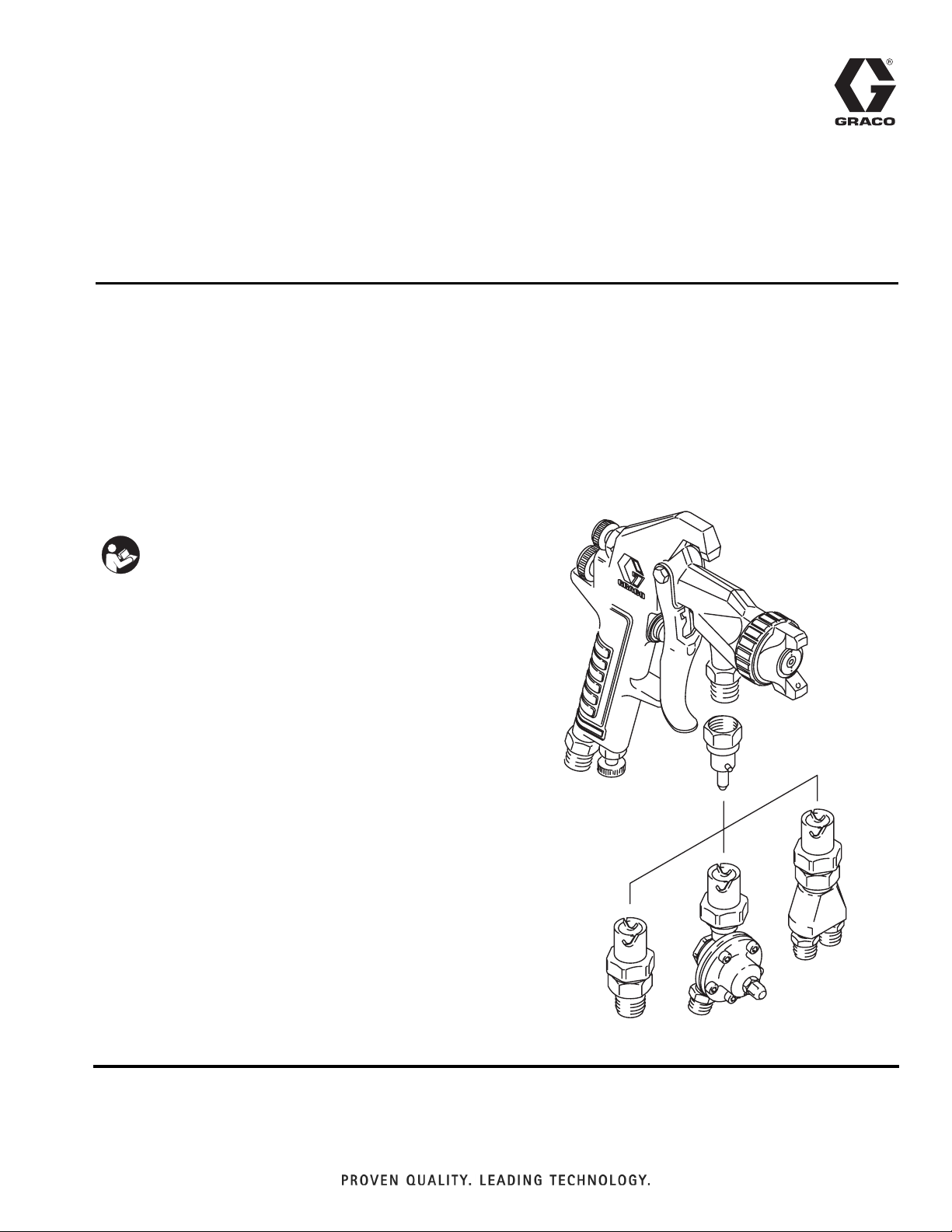
Models
Twist Lock Slip Ring Union Adapter Twist Lock
Coupler Stems
3/8 npsm
Models
Gun Mounted Fluid
Regulators
1/4 npsm inlet &
return ports
5 to 35 psi (0.5 to 2.5 bar)
Regulated Pressure
223627*
1.0 oz
Parts . . . . . . . . . . . . . . . . . . . . . . . . . . . . . . . . . . . . . 5
Accessories . . . . . . . . . . . . . . . . . . . . . . . . . . . . . . 10
Graco Standard Warranty . . . . . . . . . . . . . . . . . . . 12
208085*
1.5 oz
223628*
1.3 oz
Straight Adapters
Circulating Adapters
1/4 npsm inlet & return ports
* Stainless Steel Models
Models
3/8 npsm inlet
Models 223624* 208250 223625*
Models
223621*
7.0 oz
214019
223626*
208082*
7.5 oz
223622*
7.0 oz
223623*
7.3 oz
210097
2 307016T
Page 3

Warnings
Warnings
The following warnings are for the setup, use, grounding, maintenance, and repair of this equipment. The exclamation point symbol alerts you to a general warning and the hazard symbols refer to procedure-specific risks. When
these symbols appear in the body of this manual or on warning labels, refer back to these Warnings. Product-specific
hazard symbols and warnings not covered in this section may appear throughout the body of this manual where
applicable.
NOTE: The following warning applies only to Models 214018, 208250, 214019, and 210097, which contain aluminum housings.
WARNING
PRESSURIZED ALUMINUM PARTS HAZARD
Use of fluids that are incompatible with aluminum in pressurized equipment can cause serious chemical
reaction and equipment rupture. Failure to follow this warning can result in death, serious injury, or property damage.
• Do not use 1,1,1-trichloroethane, methylene chloride, other halogenated hydrocarbon solvents or
fluids containing such solvents.
• Many other fluids may contain chemicals that can react with aluminum. Contact your material supplier for compatibility.
307016T 3
Page 4

Installation
Installation
Connect the Fluid Hose
Regulators or Circulating Adapters
• Connect the fluid hoses to the 1/4 npsm(m) inlet and
return fittings.
Straight Adapter
• Connect a hose to the 3/8 npsm(m) inlet fitting.
Connect the Regulator or Adapter to the Gun
Model 223622
• Screw the regulator union adapter onto the gun fluid
inlet.
Models with Twist-lock Couplers
• Screw the coupler stem onto the gun inlet. Connect
the twist-lock couplers by lining up the coupler slots
with the pins on the stem, pushing the coupler onto
the stem, then twisting the coupler clockwise to lock
it.
Service
To reduce the risk of serious injury, including
splashing in the eyes or on the skin, always shut off
the air and fluid pressure to the gun and trigger the
gun to relieve pressure in the hoses before
disconnecting hoses from the regulator or adapter.
To Clean or Service the Regulator
1. Relieve the air and fluid pressures.
2. Disconnect the regulator from the gun and the
hoses from the regulator.
3. Disassemble the regulator. Refer to the Parts Drawing.
4. Clean and inspect the parts carefully.
5. Replace worn or damaged parts and reassemble
the regulator. Be sure the nylon side of the diaphragm (12) faces the fluid.
Torque Notes:
Models with Slip-ring Couplers
• Pull the slip ring back as you push the coupler onto
the stem.
Operation
NOTICE
To avoid damaging the regulator diaphragm, never
exceed 200 psi (1.4 MPa, 14 bar) Maximum Inbound
Fluid Pressure to the regulator.
To Adjust the Fluid Pressure
Trigger the gun. Turn the fluid regulator setscrew (2)
clockwise to the desired setting. Release the gun trigger, tighten the locknut (1), and install the acorn nut
(16).
Diaphragm Nut (3) onto Valve Stem (8):
6 to 10 in-lb (0.7 to 1.1 N•m)
Screws (5) into the Housing (18):
20 to 30 in-lb (2.3 to 3.4 N•m)
Cap (14) into the Housing (18):
10 to 15 ft-lb (13.5 to 20.0 N•m)
4 307016T
Page 5

Parts
Parts
Ref.
No. Part No. Description Qty.
1 100166 NUT, hex mach; No. 10-32 1
2 102433 SCREW, set, hex socket;
No. 10-32 x 3/4”
3 102980
4* 102982 O-RING; PTFE 1
5 103229
6 167244 RETAINER, spring 1
7 167245 SPRING, compression 1
8 168872 VALVE STEM 1
9 168877 HOUSING, upper 1
10* 178320 GASKET; cellulose fibre 1
11 168879 WASHER, back-up 1
12*† 178321 DIAPHRAGM; nylon & buna-n 1
13* 168881 WASHER; acetal 1
14 168884 CAP 1
15* 169597 VALVE SEAT 1
16 170303 ACORN NUT; No. 10-32 1
17* 178322 GASKET; cellulose fibre 1
18 208086 HOUSING, lower; 1
NUT, hex; stainless steel;
No. 4-40
SCREW, cap, socket head;
No. 8-32 x 3/8”
Models 223621, 208082, &
223622 only
208180 HOUSING, lower; 1
Model 223623 only
19† 101947 BALL; stainless steel;
0.375" (9.5 mm) dia.
20 186203 COUPLING NUT; stainless steel 1
21† 104338 SEAL, spring loaded; PTFE 1
22† 171887 BALL SEAT; PTFE 1
23† 171888 HOUSING, seal; acetal 1
24 186202 HOUSING, coupler; stainless steel 1
25 168890 SPRING, compression 1
26
■
VALVE SEAT; acetal 1
Ref.
No. Part No. Description Qty.
28 168891 SPRING, compression 1
■
29
1
30 100172 BALL; chrome alloy,
1
31✓ 157230 RING, retaining 1
32 168874 RING, coupler 1
5
33 168875 SPRING, compression 1
34 HOUSING, coupler 1
35✓ 168882 GASKET; acetal 1
36 223892 UNION, adapter; 3/8” npsm(f)
37** 178846 SEAL; nylon 1
38** 103075 BALL; stainless steel,
39** 178847 GUIDE, coupler stem 1
40** 178848 BALL SEAT; PTFE 1
41✓ 111279 BALL; stainless steel,
✓
Recommended “tool box” spare parts. Keep
SLIP RING COUPLER ASSY.
Includes items 30-34
0.188" (4.76 mm) dia.
swivel
0.438" (11.1 mm) dia.
0.438" (11.1 mm) dia.
these spare parts on hand to reduce down time.
*
These parts are included in Repair Kit 208380,
which may be purchased separately.
**
1
These parts are included in Repair Kit 217502,
which may be purchased separately.
†
These parts are included in Repair Kit 210786,
which may be purchased separately.
★
Accessory PTFE Diaphragm 185028 with PET
Backing Diaphragm 168880 is available. See
page 10.
■
These parts are included in Repair Kit 24U819,
which may be purchased separately.
1
3
1
1
1
307016T 5
Page 6

Parts
Coupler Stems
Ref.
No. Part No. Description Qty.
1✓ 103337 O-RING; fluoroelastomer 1
2 168868 FITTING, coupler 1
3 168869 COUPLING NUT; 3/8 npsm (f) 1
Fluid Regulators
223627 208085 223628
2
3
1
✓
Model 223622 Series A
Includes items 1-18, 35, 36
Model 223621 Series A
Includes items 1-25
20
36
24
✓
35
†23
†21
†22
†19
25
Common Parts for Regulators
14
2
NOTES
Small hole faces down
1
Torque to 10–15 ft/lb (13.5–20 N•m)
2
Nylon side MUST face fluid
3
1/4 npsm(m)
4
Torque to 6-10 in/lb (0.7-1.1 N•m)
5
Torque to 20-30 in/lb (2.3-3.4 N•m)
6
Spring inside faces down
7
Large chamfer faces up
8
*15
Model 208082 Series E
Includes items 1-19, 26-34
Model 223623 Series A
Includes items 1-18, 20, 24,
25, 37-40
✓
31
✓
31
32
8
26■
29■
33
7
✓
19
34
30
28
*4
18
20
24
39**
37**
40**
41
25
✓
8
11
17*
10*
12*†
3
13*
7
6
4
3
5
9
6
5
1
16
2
02287a
6 307016T
Page 7

Straight Adapters
NOTES
3/8 npsm(m)
1
Spring inside faces down
2
Torque to 15-25 ft/lb (20-34 N•m)
3
Model 223624 Series A
TWIST LOCK COUPLER
Includes items 3-13
3
3
4
Parts
†13
†10
†12
†9
7
11
Ref.
No. Part No. Description Qty.
3 186203 COUPLING NUT; stainless steel 1
4 186202 HOUSING, coupler; stainless steel 1
7 168890 SPRING, compression 1
9† 101947 BALL; stainless steel;
0.375" (9.5 mm) dia.
2
1
02293a
Ref.
No. Part No. Description Qty.
10† 104338 SEAL, spring loaded; PTFE 1
11 170755 HOUSING, straight adapter 1
12† 171887 BALL SEAT; PTFE 1
13† 171888 HOUSING, seal; acetal 1
1
†
These parts are included in Repair Kit 210786,
which may be purchased separately.
307016T 7
Page 8

Parts
Straight Adapters
Model 223625 Series A
TWIST LOCK COUPLER
Includes items 3, 4, 7, 24 - 27
4
3
3
4
25
24
3
26
✓
28
7
NOTES
3/8 npsm(m)
1
Small hole faces down
2
Large chamfer faces up
3
Torque to 15-25 ft-lb (20-34 N•m)
4
27
2
1
02294a
■17
■14
Model 208250 Series B
SLIP RING COUPLER
Includes items 8, 9, 14 - 22
✓
9
✓
9
16
8
19
✓
20
21
22
18
02296a
1
Ref.
No. Part No. Description Qty.
3 186203 COUPLING NUT; stainless steel 1
4 186202 HOUSING, coupler; stainless steel 1
7 168890 SPRING, compression 1
8 169472 HOUSING, straight adapter 1
9✓ 101947 BALL; stainless steel;
0.375" (9.5 mm) dia.
14■ VALVE SEAT; acetal 1
16 168891 SPRING, compression 1
17■ SLIP RING COUPLER ASSY.
Includes items 18-22
18 100172 BALL; chrome alloy,
0.188" (4.76 mm) dia.
Ref.
No. Part No. Description Qty.
21 168875 SPRING, compression 1
22 HOUSING, coupler 1
24 178846 SEAL; nylon 1
25 178847 GUIDE, coupler stem 1
26 178848 BALL SEAT; PTFE 1
1
27 180050 HOUSING, straight adapter 1
28✓ 111279 BALL; stainless steel,
0.438" (11.1 mm) dia.
✓
Recommended “tool box” spare parts. Keep on
hand to reduce downtime.
3
■
These parts are included in Repair Kit 24U819,
which may be purchased separately.
19✓ 157230 RING, retaining 1
20 168874 RING, coupler 1
8 307016T
1
Page 9

Circulating Adapters
Parts
Model 214019 Series B
TWIST LOCK COUPLER
Includes items 2, 3, 7 - 11, 15, 16
4
2
7
†16
†11
†15
†10
8
9
3
02297a
1
Model 223626 Series A
TWIST LOCK COUPLER
Stainless Steel
Includes items 4, 5, 7, 8, 10 - 16
4
4
5
†16
†11
†15
†10
8
12
13
14
2
02298a
1
Model 210097 Series B
TWIST LOCK COUPLER
Includes items 2, 3, 7, 8, 26 - 30
3
Small hole
faces down
02300a
1
2
7
28**
27**
29**
26**
8
30
3
4
NOTES
1/4 npsm(m) Small hole faces down
1 3
Spring inside faces down Torque to 15–25 ft/lb (20–34 N•m)
2 4
Ref.
No. Part No. Description Qty.
2 167394 COUPLING NUT 1
3 167395 HOSE ADAPTER; 1/4 npsm(m) 2
4 186203 COUPLING NUT; stainless steel 1
5 186202 HOUSING, coupler; stainless steel 1
7 181578 HOUSING, coupler 1
8 168890 SPRING, compression 1
9 169473 HOUSING, circulating adapter 1
10† 101947 BALL; stainless steel;
0.375" (9.5 mm) dia.
11† 104338 SEAL, spring loaded; PTFE 1
12 170755 HOUSING, straight adapter 1
13 171233 HOUSING, circulating adapter 1
Ref.
No. Part No. Description Qty.
16† 171888 HOUSING, seal; acetal 1
26** 103075 BALL; stainless steel,
0.438" (11.1 mm) dia.
27** 178846 SEAL; nylon 1
28** 178847 GUIDE, coupler stem 1
29** 178848 BALL SEAT; PTFE 1
30 169471 HOUSING, circulating adapter 1
1
†
These parts are included in Repair Kit 210786,
which may be purchased separately.
**
These parts are included in Repair Kit 217502,
which may be purchased separately.
14 171234 HOSE ADAPTER; 1/4 npsm(m) 2
15† 171887 BALL SEAT; PTFE 1
307016T 9
1
Page 10

Accessories
Accessories
Accessories must be purchased separately
PTFE Diaphragm 185028, with PET Backing
Diaphragm 168880*
Use when regulator must be submersed in a solvent
incompatible with the buna-n backing of the standard
diaphragm 178321.
*
The PTFE diaphragm must face the fluid, with the
PET diaphragm used as backing.
10 307016T
Page 11

Accessories
307016T 11
Page 12

Graco Standard Warranty
Graco warrants all equipment referenced in this document which is manufactured by Graco and bearing its name to be free from defects in
material and workmanship on the date of sale to the original purchaser for use. With the exception of any special, extended, or limited warranty
published by Graco, Graco will, for a period of twelve months from the date of sale, repair or replace any part of the equipment determined by
Graco to be defective. This warranty applies only when the equipment is installed, operated and maintained in accordance with Graco’s written
recommendations.
This warranty does not cover, and Graco shall not be liable for general wear and tear, or any malfunction, damage or wear caused by faulty
installation, misapplication, abrasion, corrosion, inadequate or improper maintenance, negligence, accident, tampering, or substitution of
non-Graco component parts. Nor shall Graco be liable for malfunction, damage or wear caused by the incompatibility of Graco equipment with
structures, accessories, equipment or materials not supplied by Graco, or the improper design, manufacture, installation, operation or
maintenance of structures, accessories, equipment or materials not supplied by Graco.
This warranty is conditioned upon the prepaid return of the equipment claimed to be defective to an authorized Graco distributor for verification of
the claimed defect. If the claimed defect is verified, Graco will repair or replace free of charge any defective parts. The equipment will be returned
to the original purchaser transportation prepaid. If inspection of the equipment does not disclose any defect in material or workmanship, repairs
will be made at a reasonable charge, which charges may include the costs of parts, labor, and transportation.
THIS WARRANTY IS EXCLUSIVE, AND IS IN LIEU OF ANY OTHER WARRANTIES, EXPRESS OR IMPLIED, INCLUDING BUT NOT
LIMITED TO WARRANTY OF MERCHANTABILITY OR WARRANTY OF FITNESS FOR A PARTICULAR PURPOSE.
Graco’s sole obligation and buyer’s sole remedy for any breach of warranty shall be as set forth above. The buyer agrees that no other remedy
(including, but not limited to, incidental or consequential damages for lost profits, lost sales, injury to person or property, or any other incidental or
consequential loss) shall be available. Any action for breach of warranty must be brought within two (2) years of the date of sale.
GRACO MAKES NO WARRANTY, AND DISCLAIMS ALL IMPLIED WARRANTIES OF MERCHANTABILITY AND FITNESS FOR A
PARTICULAR PURPOSE, IN CONNECTION WITH ACCESSORIES, EQUIPMENT, MATERIALS OR COMPONENTS SOLD BUT NOT
MANUFACTURED BY GRACO. These items sold, but not manufactured by Graco (such as electric motors, switches, hose, etc.), are subject to
the warranty, if any, of their manufacturer. Graco will provide purchaser with reasonable assistance in making any claim for breach of these
warranties.
In no event will Graco be liable for indirect, incidental, special or consequential damages resulting from Graco supplying equipment hereunder, or
the furnishing, performance, or use of any products or other goods sold hereto, whether due to a breach of contract, breach of warranty, the
negligence of Graco, or otherwise.
FOR GRACO CANADA CUSTOMERS
The Parties acknowledge that they have required that the present document, as well as all documents, notices and legal proceedings entered into,
given or instituted pursuant hereto or relating directly or indirectly hereto, be drawn up in English. Les parties reconnaissen
rédaction du présente document sera en Anglais, ainsi que tous documents, avis et procédures judiciaires exécutés, donnés ou intentés, à la suite
de ou en rapport, directement ou indirectement, avec les procédures concernées.
t avoir convenu que la
Graco Information
For the latest information about Graco products, visit www.graco.com.
For patent information, see www.graco.com/patents.
TO PLACE AN ORDER, contact your Graco distributor or call to identify the nearest distributor.
Phone: 612-623-6921 or Toll Free: 1-800-328-0211 Fax: 612-378-3505
All written and visual data contained in this document reflects the latest product information available at the time of publication.
GRACO INC. AND SUBSIDIARIES • P.O. BOX 1441 • MINNEAPOLIS MN 55440-1441 • USA
Copyright 1997, Graco Inc. All Graco manufacturing locations are registered to ISO 9001.
Graco reserves the right to make changes at any time without notice.
Original instructions.
This manual contains English. MM 307016
Graco Headquarters: Minneapolis
International Offices: Belgium, China, Japan, Korea
www.graco.com
Revision T, November, 2013
 Loading...