

Page 1
9
INSTRUCTIONS-PARTS LIST
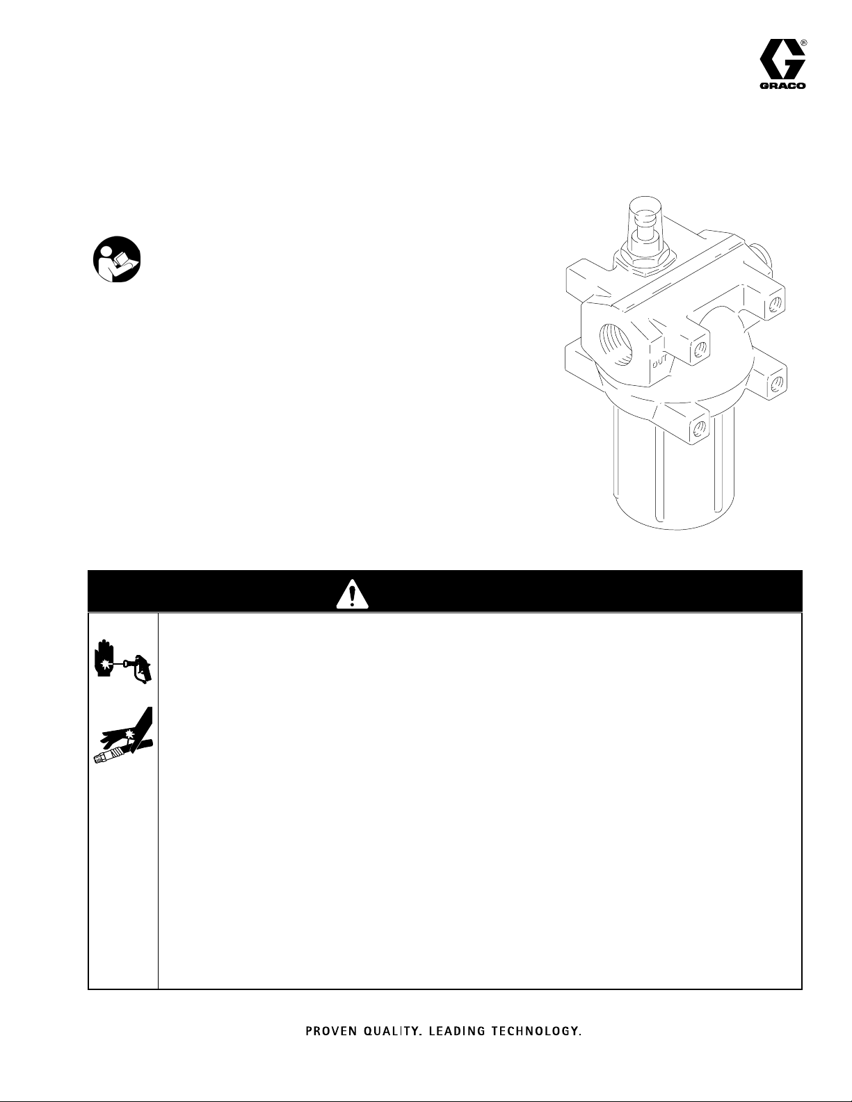
HIGH PRESSURE, MEDIUM VOLUME
“red alert” Filters
Important Safety Instructions
Read all warnings and instructions in this
manual. Save these instructions.
3000 psi (210 bar) Maximum Working Pressure
Model 207994: with 30 mesh (590 micron) element
Model 207995: with 60 mesh (250 micron) element
Model 207996: with 100 mesh (149 micron) element
Model 207997: with 150 mesh (95 micron) element
Model 207998: with 200 mesh (74 micron) element
Model 207999: with 0.040 in. (1 mm) stab point element
Model 208000: with 0.050 in. (1.3 mm) stab point element
Model 102929: less element--see back page for element numbers
306987J
077
WARNING
SKIN INJECTION HAZARD
Spray from the gun, hose leaks, or ruptured components can inject fluid into your body and cause
extremely serious injury, including the need for amputation. Fluid splashed in the eyes or on the skin
can also cause serious injury.
D Fluid injected into the skin might look like just a cut, but it is a serious injury. Get immediate surgi-
cal treatment.
D Do not point the gun at anyone or at any part of the body.
D Do not put your hand or fingers over the spray tip.
D Do not stop or deflect leaks with your hand, body, glove or rag.
D Follow the Pressure Relief Procedure on page 4 whenever you: are instructed to relieve pres-
sure; stop spraying; clean, check, or service the equipment; and install or clean the spray tip.
D Tighten all fluid connections before operating the equipment.
D Check the hoses, tubes, and couplings daily. Replace worn, damaged, or loose parts immediately.
Permanently coupled hoses cannot be repaired; replace the entire hose.
Page 2
INSTRUCTIONS
WARNING
EQUIPMENT MISUSE HAZARD
Equipment misuse can cause the equipment to rupture or malfunction and result in serious injury.
D This equipment is for professional use only.
D Read all instruction manuals, tags, and labels before operating the equipment.
D Use the equipment only for its intended purpose. If you are uncertain about usage, call your Graco
distributor.
D Do not alter or modify this equipment. Use only genuine Graco parts and accessories.
D Check equipment daily. Regular cleaning and inspection of the filter, based on the degree and kind
of service, is essential. Repair or replace worn or damaged parts immediately.
D Do not exceed the maximum working pressure of the lowest rated system component. Refer to the
Technical Data on page 6 for the maximum working pressure of this equipment.
D Use fluids and solvents which are compatible with the equipment wetted parts. Refer to the Tech-
nical Data section of all equipment manuals. Read the fluid and solvent manufacturer’s warnings.
D Never use 1,1, 1-trichloroethane, methylene chloride, other halogenated hydrocarbon solvents or
fluids containing such solvents in pressurized aluminum equipment. Such use could result in a
chemical reaction, with the possibility of explosion.
D Comply with all applicable local, state, and national fire, electrical, and safety regulations.
TOXIC FLUID HAZARD
Hazardous fluid or toxic fumes can cause serious injury or death if splashed in the eyes or on the skin,
inhaled, or swallowed.
D Know the specific hazards of the fluid you are using.
D Store hazardous fluid in an approved container. Dispose of hazardous fluid according to all local,
state and national guidelines.
D Always wear protective eyewear, gloves, clothing and respirator as recommended by the fluid and
solvent manufacturer.
2 306987
Page 3

Installation
To clean or service the filter without shutting down the
system, install a dual filter or a filter by-pass system as
explained below.
NOTE: Be sure to allow 4.5 inches (114 mm) minimum
clearance below the filter to ease removal of the filter
bowl (10).
Dual Filter System
This setup enables you to redirect the fluid to another
filter while one filter is cleaned or serviced.
Install two filters as shown in Fig 1. Both filters must
have an adapter (A) and drain valve (B) in the filter
bowl (10) to relieve fluid pressure and drain the filter
before removing the bowl. Install four suitable shut-off
valves (D), one at each filter inlet and outlet, to redirect
the fluid and isolate the filter not in use.
Filter By-pass System
This setup enables you to redirect the fluid through
pipes that by-pass the filter while cleaning or servicing
the filter.
Install the filter and by-pass pipes as shown in Fig 2.
An adapter (A) and drain valve (B) must be installed in
the filter bowl (10) to relieve fluid pressure and drain
the filter before removing the bowl. Install four suitable
shut-off valves (D), one at the filter inlet; the filter
outlet; the by-pass pipe inlet; and the by-pass pipe
outlet, to redirect the fluid and isolate the filter while
cleaning or servicing the filter.
Dual Filter System
D
DD
Fig 1
Filter Bypass System
D D D
Fig 2
10
10
A
B
A
B
D
0780
D
0781
306987 3
Page 4

Service
Pressure Relief Procedure
WARNING
SKIN INJECTION HAZARD
The system pressure must be manually
relieved to prevent the system from
starting or spraying accidentally. Fluid
under high pressure can be injected through the
skin and cause serious injury. To reduce the risk of
an injury from injection, splashing fluid, or moving
parts, follow the Pressure Relief Procedure
whenever you:
D are instructed to relieve the pressure,
D stop spraying,
D check or service any of the system equipment,
D or install or clean the spray tip.
1. Lock the gun trigger safety.
2. Turn off the power to the pump.
3. Unlock the gun trigger safety.
4. Hold a metal part of the gun firmly to the side of a
grounded metal pail, and trigger the gun to relieve
pressure.
5. Lock the gun trigger safety.
Indicator
The indicator provides gradual warning of a dirty
element. When the indicator shown 3/4 red, clean the
element. If not cleaned promptly, the filter by-pass
valve opens and fluid will not be filtered.
Replace the indicator assembly (1) if the indicator isn’t
working correctly (it’s always red or never red).
By-pass Valve
The valve opens when a dirty element causes the
filter’s outlet pressure to drop 25 psi (2 bar) below the
inlet pressure. This keeps the system pressure steady
and prevents the element from collapsing. Replace the
by-pass valve (2) if it is damaged or worn.
Fluoroelastomer O-Ring and O-Ring Backup
These o-rings seal the bowl (10) to the housing (3). If
fluid leaks around the bowl, replace the o-ring (8) and
o-ring backup (9).
Remove the bowl and o-rings. Clean the parts in a
compatible solvent. Be careful not to damage the
o-rings or sealing surfaces of the bowl and housing.
Before assembling, lubricate the parts with no. 2
grease. BE SURE to install the o-ring backup with the
groove facing up.
Bowl, Element and Spring
Keep a spare bowl (10), element (6) and spring (7) on
hand to reduce down time. Before removing the bowl,
direct the fluid through the bypass system or shut
down the system. Relieve fluid pressure by opening
the drain valve (B).
6. Keeping your hands away from the end of the
drain valve, slowly open the drain valves (required
in your system), having a container ready to catch
the drainage.
7. Leave the drain valves open until you are ready to
use the system again.
CAUTION
If the filter will not be used for awhile, thoroughly
clean all the parts in solvent and blow them dry
before the paint dries and clogs the filter. To avoid
damaging parts, DO NOT clean them with a wire
brush or sharp object.
4 306987
Holding the bowl with a wrench to keep it from turning,
screw the drain plug (12) out. After the fluid has
drained out, remove the bowl, element, and spring.
Replace immediately with the spare bowl, element and
spring to keep the paint from drying on the housing (3)
and other parts. Install the element with the dome end
up. Lubricate the threads of the bowl before screwing it
into the housing; tighten it securely.
Clean the bowl, element and spring you removed with
a compatible solvent before the paint dries; DO NOT
use a wire brush or sharp object for cleaning. Clean
the filter element (6) with a small paint brush. Blow out
lodged particles with air, and inspect for damage.
Replace element if ruptured. Store clean parts until
needed.
Page 5

Parts
Torque to 50 in–lb
1
1-1/4” npt(f)
2
inlet and outlet
1/2-13 UNC thread
3
mounting holes
3/4-16 UNF thread
4
plugged drain
1
1
Ref.
No. Part No. Description Qty.
2
1 104784 INDICATOR, filter 1
2 104128 VALVE, by-pass 1
3 171430 HOUSING, filter 1
2
4
5
3
3
6
7
8
9
10
11
12
4
0782
4 100055 SCREW, drive; type U,
No. 6 x 1/4” 2
5 172205 PLATE, instruction 1
6* 108111 ELEMENT, 30 MH Filter
(Model 207994 only) 1
108112 ELEMENT, 60 MH Filter
(Model 207995 only) 1
108113 ELEMENT, 100 MH Filter
(Model 207996 only) 1
108115 ELEMENT, 150 MH Filter
(Model 207997 only) 1
108114 ELEMENT, 200 MH Filter
(Model 207998 only) 1
108119 ELEMENT, 0.040” SP Filter
(Model 207999 only) 1
108120 ELEMENT, 0.050” SP Filter
(Model 208000 only) 1
7* 104127 SPRING, element 1
8* 104131 O-RING, fluoroelastomer; see
Accessories for ethylene propylene
packing 1
9* 104129 BACKUP, o-ring, fluoroelastomer; see
Accessories for PTFE o-ring 1
10* 171431 BOWL, filter 1
11* 104444 O-RING, fluoroelastomer 1
12 104126 PLUG, boss; 3/4-16 UNF 1
*Recommended “tool box” spare parts. Keep on hand to
reduce down time
NOTE: MH indicates a mesh filter SP indicates a stab point
filter.
306987 5
Page 6

Accessories
Mounting Hole
CONVERSION O-RINGS
For use with fluids not compatible with fluoroelastomer.
105278 O-Ring, Ethylene-propylene
105277 Backup, o-ring, PTFE
ADAPTER 105276
3000 psi (210 bar) MAXIMUM WORKING PRESSURE
3/4-16 UNF x 1/4 npt; Adapts bowl to Drain Valves
210657 or 214037 (see below).
DRAIN VALVES
5000 psi (350 bar) MAXIMUM WORKING PRESSURE
Installs in Adapter 105276 for relieving fluid pressure in
the filter.
210657 1/4 npt(m) Fluoroelastomer Seals
214037 1/4 npt(m) PTFE Seals
FILTER BY-PASS VALVE 111523
Opens at 45 psi (3 bar), 20 GPM (76 kg/min.). For use
in mastic applications.
Layout
3.60”
(90 mm)
3.44”
(85 mm)
4.00”
(100 mm)
Technical Data
Dimensions 6.56 in. (167 mm) wide. . . . . . . . . . . . . . . . .
6.56 in. (167 mm deep
13.08 in. (335 mm) high
Weight 30 lb 8 oz (13.8 kg). . . . . . . . . . . . . . . . . . . . . . . .
Maximum Working Pressure 3000 psi (210 bar). . . . . .
Flow capacity
Mastics-Sealers 6 gal. per min. (23 liters/min). . . . . .
(stab point elements)
Paints to 20 gal. per min. (75 liters/min). . . . . . . . . .
Wetted Parts Aluminum, Iron, Fluoroelastomer,. . . . . .
PTFE, Plated Steel
Filtering Area 66 in2 (425 cm2)--stab point elements. .
226 in2 (1450 cm2)--mesh elements
Temperature –40_F to 200_F . . . . . . . . . . . . . . . . . . . . .
0.56”
(14
mm)
dia. (4)
0783
(mesh elements)
Important Phone
Manual Change
Numbers
Summary
Elements 108111 through 108120 are now standard.
All written and visual data contained in this document reflects the latest product information available at the time of publication.
Graco reserves the right to make changes at any time without notice.
This manual contains English. MM 306987
Graco Headquarters: Minneapolis
International Offices: Belgium, China, Japan, Korea
GRACO INC.ąP.O. BOX 1441ąMINNEAPOLIS, MNą55440-1441
Copyright 1977, Graco Inc. is registered to I.S. EN ISO 9001
www.graco.com
Revised February 2008
6 306987
TO PLACE AN ORDER, contact your Graco distributor, or call this number to identify the distributor closest to you: 1–800–328–0211 Toll Free
 Loading...