

Page 1
Instructions – Parts List
Lube Equipment Couplers,
Adapters, Nozzles, and
Z-Swivels
Important Safety Instructions
Read all warnings and instructions in this manual.
Save these instructions.
306708H
ENG
GRACO INC. P.O. BOX 1441 MINNEAPOLIS, MN 55440–1441
Copyright 2002, Graco Inc. is registered to I.S. EN ISO 9001
Page 2
Symbols
Pressure Relief Procedure
1. Turn off the power supply to the pump.
Warning Symbol
WARNING
This symbol alerts you to the possibility of serious
injury or death if you do not follow the instructions.
WARNING
WARNING
EQUIPMENT MISUSE HAZARD
Equipment misuse can cause the equipment to rupture or malfunction and result in serious injury.
INSTRUCTIONS
D This equipment is for professional use only.
D Read all instruction manuals, tags, and labels before operating the equipment.
D Use the equipment only for its intended purpose. If you are not sure, call Graco Technical Assis-
tance at 1–800–543–0339.
D Use only genuine Graco parts and accessories.
2. Trigger the valve into a waste container to relieve
pressure.
3. Open any bleed-type master air valves and fluid
drain valves in the system.
4. Leave the drain valve open until you have completed repairs and are ready to pressurize the system.
D Check equipment daily. Repair or replace worn or damaged parts immediately.
D Do not exceed the maximum working pressure of the lowest rated system component. Refer to
the part’s drawing for the maximum working pressure of this component.
D Use fluids and solvents which are compatible with the equipment wetted parts. Refer to the Tech-
nical Data section of all equipment manuals. Read the fluid and solvent manufacturer’s warn-
ings.
D Do not use 1,1,1–trichloroethane, methylene chloride, other halogenated hydrocarbon solvents or
fluids containing such solvents in pressurized aluminum equipment. Such use could result in a
chemical reaction, with the possibility of explosion.
D Do not use hoses to pull equipment.
D Route hoses away from traffic areas, sharp edges, moving parts, and hot surfaces. Do not ex-
pose Graco hoses to temperatures above 82_C (180_F) or below –40_C (–40_F).
D Do not lift pressurized equipment.
D Comply with all applicable local, state, and national fire, electrical, and safety regulations.
3067082
Page 3
WARNING
WARNING
SKIN INJECTION HAZARD
Spray from the dispensing valve, leaks or ruptured components can inject fluid into your body and
cause extremely serious injury, including the need for amputation. Fluid splashed in the eyes or on
the skin can also cause serious injury.
D Fluid injected into the skin may look like just a cut, but it is a serious injury. Get immediate surgi-
cal treatment.
D Do not point the dispensing valve at anyone or at any part of the body.
D Do not put your hand or fingers over the end of the dispensing valve.
D Do not stop or deflect leaks with your hand, body, glove or rag.
D Use only extensions and no-drip tips which are designed for use with your dispensing valve.
D Do not use a low pressure flexible nozzle with this equipment.
D Follow the Pressure Relief Procedure on page 2 before cleaning, checking or servicing the
equipment.
D Never attempt to force lubricant into a fitting.
D Tighten all fluid connections before operating the equipment.
D Check the hoses, tubes, and couplings daily. Replace worn or damaged parts immediately. Do
not repair high pressure couplings; you must replace the entire hose.
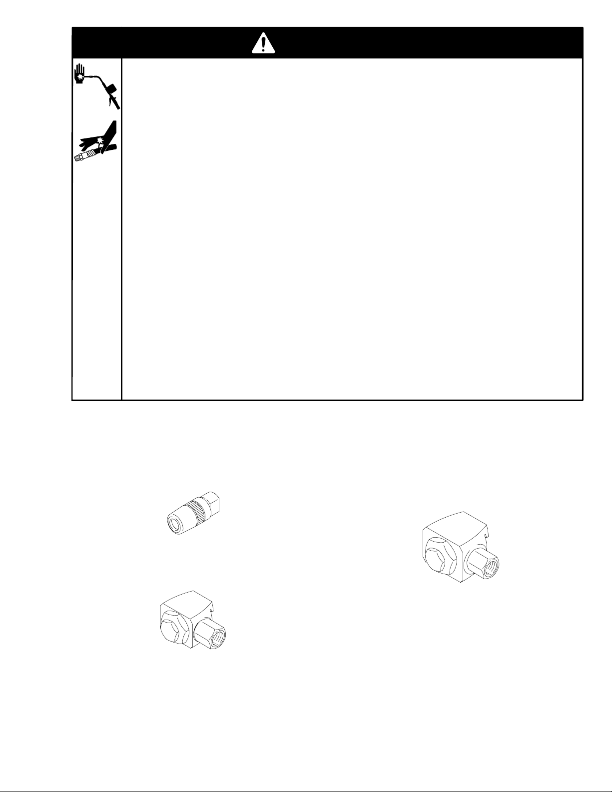
Hydraulic Couplers
Taper Nose Hydraulic Coupler 200325
8000 psi (560 bar) Maximum Working Pressure
Standard Button-Head Hydraulic Coupler
200020
2500 psi (175 bar) Maximum Working Pressure
Giant Button-Head Hydraulic Coupler
200021
2000 psi (140 bar) Maximum Working Pressure
3588
3590
3589
306708 3
Page 4

Adapters
Hydraulic Adapter Accessory Kit 205592
See the separate listing for each kit component for replacement parts and maximum working pressures.
Ref.
No. Part No. Description Qty.
1 201881 ADAPTER, hydraulic-to-push;
See below 1
2 203504 HOSE, nozzle; with lock-sleeve
connector; See page 6 1
4 205532 ADAPTER, hydraulic-to-steel needle;
See below 1
3 205554 ADAPTER, plug; See page 5 1
4 205568 ADAPTER, nylon needle; See at right 1
5 205582 ADAPTER, hydraulic-to-nylon needle;
See at right 1
Low Pressure Adapters
Hydraulic-to-Steel Needle Adapter 205532
250 psi (18 bar) Maximum Working Pressure
For flush fittings
Ref.
No. Part No. Description Qty.
1 164799 NEEDLE, adapter 1
2 203497 CONNECTOR, locking sleeve 1
Hydraulic-to-Nylon Needle Adapter 205582
250 psi (18 bar) Maximum Working Pressure
For removable plugs
Ref.
No. Part No. Description Qty.
1 164771* NOZZLE, fluid 1
2 164757 TUBE, adapter; 2 in. (51 mm) long 1
3 203497 CONNECTOR, locking sleeve 1
*Recommended spare part to keep on hand
3
2
1
0109
2
1
Hydraulic-to-Push Adapter 201881
250 psi (18 bar) Maximum Working Pressure
For U-joints and low pressure service
Nylon Needle Adapter 205568
250 psi (18 bar) Maximum Working Pressure
For removable plugs
REF
NO. PART NO. DESCRIPTION QTY
0108
1 164771* NOZZLE, fluid 1
2 164772 TUBE, adapter, needle; 1/8 npt;
5 in. (127 mm) long 1
*Recommended spare part to keep on hand
2
1
0107
03591
3067084
Page 5

Adapters
90_ Lube Adapter 223187
250 psi (18 bar) Maximum Working Pressure
Ref.
No. Part No. Description Qty.
1 203497 CONNECTOR, locking sleeve 1
2 185914 ADAPTER 1
3 151249 NIPPLE 1
4 156563 TIP, nozzle 1
1
3
2
4
0110
High Pressure Adapters
Locking Sleeve Connector 203497
6000 psi (420 bar) Maximum Working Pressure
For quick connection to taper nose coupler
03593
360_ Grease Swivel & Coupler Kit 203597
6000 psi (420 bar) Maximum Working Pressure
Ref.
No. Part No. Description Qty.
1 200325 COUPLER, hydraulic 1
2 203198 SWIVEL, 360_ 1
1 2
03595
Medium Pressure Adapter
90_ Plug Adapter 205554
700 psi (49 bar) Maximum Working Pressure
For removable plugs
Ref.
No. Part No. Description Qty.
1 205559 NUT, lock; 1/4–28 1
2 164762 ADAPTER, 90_ 1
3 100846 FITTING, hydraulic, 1/4–28 thread 1
2
1
3
0106
360_ Grease Swivel 203198
6000 psi (420 bar) Maximum Working Pressure
03592
Straight Swivels
8000 psi (560 bar) Maximum Working Pressure
204082 1/8 npt(m) x 1/8 npt(f)
204083 1/4 npt(m) x 1/8 npt(f)
204084 1/4 npt(m) x 1/4 npt(f)
03594
306708 5
Page 6

Grease Nozzles
Hose Nozzle 204204
5000 psi (350 bar) Maximum Working Pressure
Ref.
No. Part No. Description Qty.
1 200325 HYDRAULIC, coupler 1
2 151277 TUBE, adapter; 2.5 in. (64 mm) long 1
3 100451 COUPLING, pipe; 1/8 npt 1
4 109145 HOSE, coupled; 1/8 npt(m);
0.25” (6.4 mm) ID; 12 in. (305 mm) long1
4
Hand Grip
3
2
1
Install Coupler (1) on
this end ONLY
0104
WARNING
To reduce the risk of serious injury, including fluid
injection:
Standard Grease Nozzle 200389
8000 psi (560 bar) Maximum Working Pressure
REF
NO. PART NO. DESCRIPTION QTY
1 TUBE, adapter; 1/8 npt(m); 6 in.
(152 mm) long; Not sold separately 1
2 200325 COUPLER, hydraulic 1
1
2
0099
Swivel Grease Nozzle
6000 psi (420 bar) Maximum Working Pressure
204072 6” (152 mm) long
204897 12” (305 mm) long
Ref.
No. Part No. Description Qty.
150622 TUBE, extension; 1/8 npt(m);
1 6 in. (152 mm) long; 204072 only 1
155836 TUBE, extension; 1/8 npt(m);
12 in. (305 mm) long; 204897 only 1
2 200325 COUPLER, hydraulic;
See separate parts list on front cover 1
3 203198 SWIVEL, 360_ 1
2
3
D Only install a coupler on the hand grip end of the hose,
as shown above. Never install a coupler on the other
end of the hose.
D Never use the flexible extension without the hand grip
in place.
Hose Nozzle 203504
5000 psi (350 bar) Maximum Working Pressure
With Lock Sleeve Connector
Ref.
No. Part No. Description Qty.
1 154289 HOSE, 3/16 in. ID, 12 in. long,
cpld 1/8 npt (m) 1
2 203497 CONNECTOR, locking sleeve 1
3 200325 COUPLER, hydraulic 1
1
3
2
1
0105
Z-Swivels
Z-Swivels
6500 psi (450 bar) Maximum Working Pressure
202577 1/4–18 npt
224569 3/8–18 npt
202579 1/8–27 npt (m); 1/4–18 npt (f)
24H614 1/4–19 bspt
24H615 1/4–19 bspp
0103
03596
3067086
Page 7

NOTES
306708 7
Page 8

Graco Standard Warranty
Graco warrants all equipment manufactured by Graco and bearing its name to be free from defects in material and workmanship on the
date of sale to the original purchaser for use. With the exception of any special, extended, or limited warranty published by Graco,
Graco will, for a period of twelve months from the date of sale, repair or replace any part of the equipment determined by Graco to be
defective. This warranty applies only when the equipment is installed, operated and maintained in accordance with Graco’s written
recommendations.
This warranty does not cover, and Graco shall not be liable for general wear and tear, or any malfunction, damage or wear caused by
faulty installation, misapplication, abrasion, corrosion, inadequate or improper maintenance, negligence, accident, tampering, or substitution of non–Graco component parts. Nor shall Graco be liable for malfunction, damage or wear caused by the incompatibility of
Graco equipment with structures, accessories, equipment or materials not supplied by Graco, or the improper design, manufacture,
installation, operation or maintenance of structures, accessories, equipment or materials not supplied by Graco.
This warranty is conditioned upon the prepaid return of the equipment claimed to be defective to an authorized Graco distributor for
verification of the claimed defect. If the claimed defect is verified, Graco will repair or replace free of charge any defective parts. The
equipment will be returned to the original purchaser transportation prepaid. If inspection of the equipment does not disclose any defect
in material or workmanship, repairs will be made at a reasonable charge, which charges may include the costs of parts, labor, and
transportation.
THIS WARRANTY IS EXCLUSIVE, AND IS IN LIEU OF ANY OTHER WARRANTIES, EXPRESS OR IMPLIED, INCLUDING BUT
NOT LIMITED TO WARRANTY OF MERCHANTABILITY OR WARRANTY OF FITNESS FOR A PARTICULAR PURPOSE.
Graco’s sole obligation and buyer’s sole remedy for any breach of warranty shall be as set forth above. The buyer agrees that no other
remedy (including, but not limited to, incidental or consequential damages for lost profits, lost sales, injury to person or property, or any
other incidental or consequential loss) shall be available. Any action for breach of warranty must be brought within two (2) years of the
date of sale.
Graco makes no warranty, and disclaims all implied warranties of merchantability and fitness for a particular purpose in connection
with accessories, equipment, materials or components sold but not manufactured by Graco. These items sold, but not manufactured
by Graco (such as electric motors, switches, hose, etc.), are subject to the warranty, if any, of their manufacturer. Graco will provide
purchaser with reasonable assistance in making any claim for breach of these warranties.
In no event will Graco be liable for indirect, incidental, special or consequential damages resulting from Graco supplying equipment
hereunder, or the furnishing, performance, or use of any products or other goods sold hereto, whether due to a breach of contract,
breach of warranty, the negligence of Graco, or otherwise.
FOR GRACO CANADA CUSTOMERS
The parties acknowledge that they have required that the present document, as well as all documents, notices and legal proceedings
entered into, given or instituted pursuant hereto or relating directly or indirectly hereto, be drawn up in English. Les parties reconnaissent avoir convenu que la rédaction du présente document sera en Anglais, ainsi que tous documents, avis et procédures judiciaires
exécutés, donnés ou intentés à la suite de ou en rapport, directement ou indirectement, avec les procedures concernées.
Graco Phone Number
TO PLACE AN ORDER, contact your Graco distributor, or call this number to identify the distributor closest to you:
Phone: 612–623–6928, or Toll Free: 1–800–533–9655 Toll Free, Fax: 612–378–3590.
All written and visual data contained in this document reflects the latest product information available at the time of publication.
Graco reserves the right to make changes at any time without notice.
This manual contains English. MM 306708
International Offices: Belgium, Korea, China, Japan
Graco Headquarters: Minneapolis
GRACO INC. P.O. BOX 1441 MINNEAPOLIS, MN 55440–1441
Graco Inc. is registered to ISO 9001
www.graco.com
306708 Rev. H 5/2011
3067088
 Loading...