

Page 1
Instructions
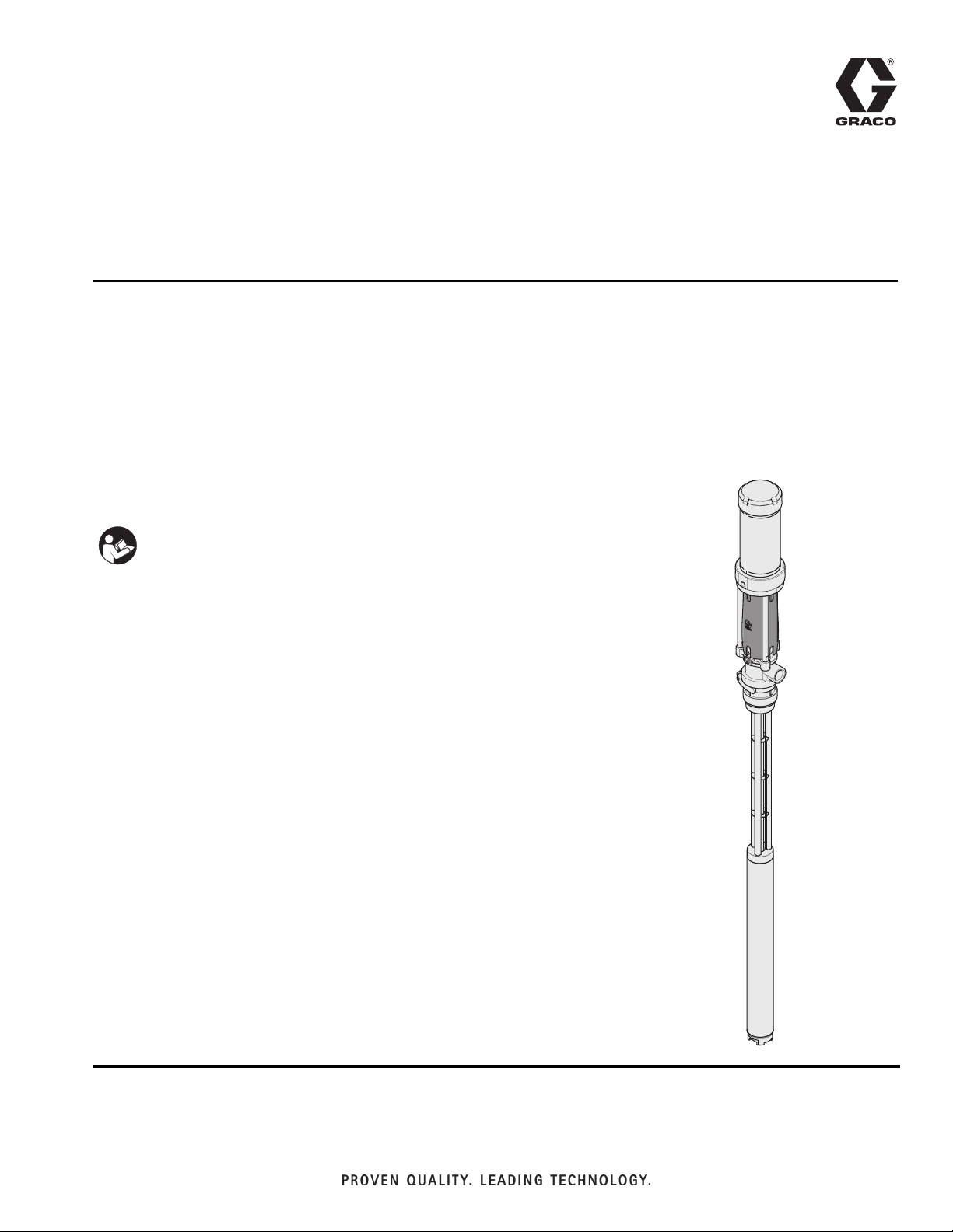
T2
311882T
2:1 Ratio Transfer Pump
For use with polyurethane foam, polyurea, and similar non-flammable materials. For
professional use only.
Not for use in explosive atmospheres.
Model 295616 (55-gallon drum)
180 psi (1.2 MPa, 12 bar) Maximum Air Working Pressure
405 psi (2.7 MPa, 27 bar) Maximum Fluid Working Pressure
EN
Important Safety Instructions
Read all warnings and instructions in this
manual. Save these instructions.
WLD
Page 2
Warnings
Contents
Warnings . . . . . . . . . . . . . . . . . . . . . . . . . . . . . . . . . 2
Moisture Sensitivity of Isocyanates . . . . . . . . . . . . 4
Isocyanate Hazard . . . . . . . . . . . . . . . . . . . . . . . 4
Foam Self-Ignition . . . . . . . . . . . . . . . . . . . . . . . . 4
Keep Components A and B Separate . . . . . . . . . 4
Changing Materials . . . . . . . . . . . . . . . . . . . . . . . 4
Typical Installation . . . . . . . . . . . . . . . . . . . . . . . . . 5
Typical Installation, without Circulation . . . . . . . . 5
Typical Installation, with Circulation . . . . . . . . . . 6
Typical Installation for Lubrication Applications . 7
Installation . . . . . . . . . . . . . . . . . . . . . . . . . . . . . . . . 8
System Accessories . . . . . . . . . . . . . . . . . . . . . . 8
Air Line Accessories . . . . . . . . . . . . . . . . . . . . . . 8
Fluid Line Accessories . . . . . . . . . . . . . . . . . . . . 8
Setup . . . . . . . . . . . . . . . . . . . . . . . . . . . . . . . . . . . . . 9
Grounding the System . . . . . . . . . . . . . . . . . . . 10
Warnings
Operation . . . . . . . . . . . . . . . . . . . . . . . . . . . . . . . . 11
Pressure Relief Procedure . . . . . . . . . . . . . . . . 11
Flushing . . . . . . . . . . . . . . . . . . . . . . . . . . . . . . . 11
Daily Startup . . . . . . . . . . . . . . . . . . . . . . . . . . . 11
Daily Shutdown . . . . . . . . . . . . . . . . . . . . . . . . . 11
Air Motor Repair . . . . . . . . . . . . . . . . . . . . . . . . . . . 12
Pump Lower Repair . . . . . . . . . . . . . . . . . . . . . . . . 14
Reassembly . . . . . . . . . . . . . . . . . . . . . . . . . . . . . . 17
Troubleshooting . . . . . . . . . . . . . . . . . . . . . . . . . . . 17
Parts - Model 295616 . . . . . . . . . . . . . . . . . . . . . . . 18
Accessories . . . . . . . . . . . . . . . . . . . . . . . . . . . . . . 20
Technical Data . . . . . . . . . . . . . . . . . . . . . . . . . . . . 22
Dimensions . . . . . . . . . . . . . . . . . . . . . . . . . . . . 22
Performance Chart . . . . . . . . . . . . . . . . . . . . . . 23
Graco Standard Warranty . . . . . . . . . . . . . . . . . . . 24
Graco Information . . . . . . . . . . . . . . . . . . . . . . . . . 24
The following warnings are for the setup, use, grounding, maintenance, and repair of this equipment. The exclamation point symbol alerts you to a general warning and the hazard symbol refers to procedure-specific risk. Refer back
to these warnings. Additional, product-specific warnings may be found throughout the body of this manual where
applicable.
WARNING
TOXIC FLUID OR FUMES HAZARD
Toxic fluids or fumes can cause serious injury or death if splashed in the eyes or on skin, inhaled, or
swallowed.
• Read MSDS’s to know the specific hazards of the fluids you are using.
• Store hazardous fluid in approved containers, and dispose of it according to applicable guidelines.
• Always wear impervious gloves when spraying or cleaning equipment.
PERSONAL PROTECTIVE EQUIPMENT
You must wear appropriate protective equipment when operating, servicing, or when in the operating
area of the equipment to help protect you from serious injury, including eye injury, inhalation of toxic
fumes, burns, and hearing loss. This equipment includes but is not limited to:
• Protective eyewear
• Clothing and respirator as recommended by the fluid and solvent manufacturer
•Gloves
• Hearing protection
2 311882T
Page 3
Warnings
WARNING
EQUIPMENT MISUSE HAZARD
Misuse can cause death or serious injury.
• Do not operate the unit when fatigued or under the influence of drugs or alcohol.
• Do not exceed the maximum working pressure or temperature rating of the lowest rated system
component. See Technical Data in all equipment manuals.
• Use fluids and solvents that are compatible with equipment wetted parts. See Technical Data in all
equipment manuals. Read fluid and solvent manufacturer’s warnings. For complete information
about your material, request MSDS forms from distributor or retailer.
• Check equipment daily. Repair or replace worn or damaged parts immediately with genuine manufacturer’s replacement parts only.
• Do not alter or modify equipment.
• Use equipment only for its intended purpose. Call your distributor for information.
• Route hoses and cables away from traffic areas, sharp edges, moving parts, and hot surfaces.
• Do not kink or over bend hoses or use hoses to pull equipment.
• Keep children and animals away from work area.
• Comply with all applicable safety regulations.
PRESSURIZED EQUIPMENT HAZARD
Fluid from the gun/dispense valve, leaks, or ruptured components can splash in the eyes or on skin and
cause serious injury.
•Follow Pressure Relief Procedure in this manual, when you stop spraying and before cleaning,
checking, or servicing equipment.
• Tighten all fluid connections before operating the equipment.
• Check hoses, tubes, and couplings daily. Replace worn or damaged parts immediately.
MOVING PARTS HAZARD
Moving parts can pinch or amputate fingers and other body parts.
• Keep clear of moving parts.
• Do not operate equipment with protective guards or covers removed.
• Pressurized equipment can start without warning. Before checking, moving, or servicing equipment,
follow the Pressure Relief Procedure in this manual. Disconnect power or air supply.
311882T 3
Page 4
Moisture Sensitivity of Isocyanates
Moisture Sensitivity of Isocyanates
Isocyanates (ISO) are catalysts used in two component
foam and polyurea coatings. ISO will react with moisture
(such as humidity) to form small, hard, abrasive crystals,
which become suspended in the fluid. Eventually a film
will form on the surface and the ISO will begin to gel,
increasing in viscosity. If used, this partially cured ISO
will reduce performance and the life of all wetted parts.
The amount of film formation and rate of
crystallization varies depending on the blend of
ISO, the humidity, and the temperature.
To prevent exposing ISO to moisture:
• Always use a sealed container with a desiccant
dryer in the vent, or a nitrogen atmosphere. Never
store ISO in an open container.
• Use moisture-proof hoses specifically designed for
ISO, such as those supplied with your system.
• Never use reclaimed solvents, which may contain
moisture. Always keep solvent containers closed
when not in use.
• Never use solvent on one side if it has been
contaminated from the other side.
• Always lubricate threaded parts with Part 217374
ISO pump oil or grease when reassembling.
Isocyanate Hazard
Read material manufacturer’s warnings and material
MSDS to know the specific hazards of isocyanates.
Use equipment in a well-ventilated area. Wear
respirator, gloves, and protective clothing when using
isocyanates.
Foam Self-Ignition
Some materials may become self-igniting if applied
too thick. Read material manufacturer’s warnings and
material MSDS.
Keep Components A and B Separate
CAUTION
To prevent cross-contamination of the equipment’s
wetted parts, never interchange component A and
component B.
Changing Materials
• When changing materials, flush the equipment
multiple times to ensure it is thoroughly clean.
• Check with your material manufacturer for chemical
compatibility.
• Some materials use catalyst on the A side, but
some applications may use catalyst on the B side.
• Epoxies often have amines on the B (catalyst) side.
Polyurethanes often have amines on the B (resin)
side.
4 311882T
Page 5
Typical Installation
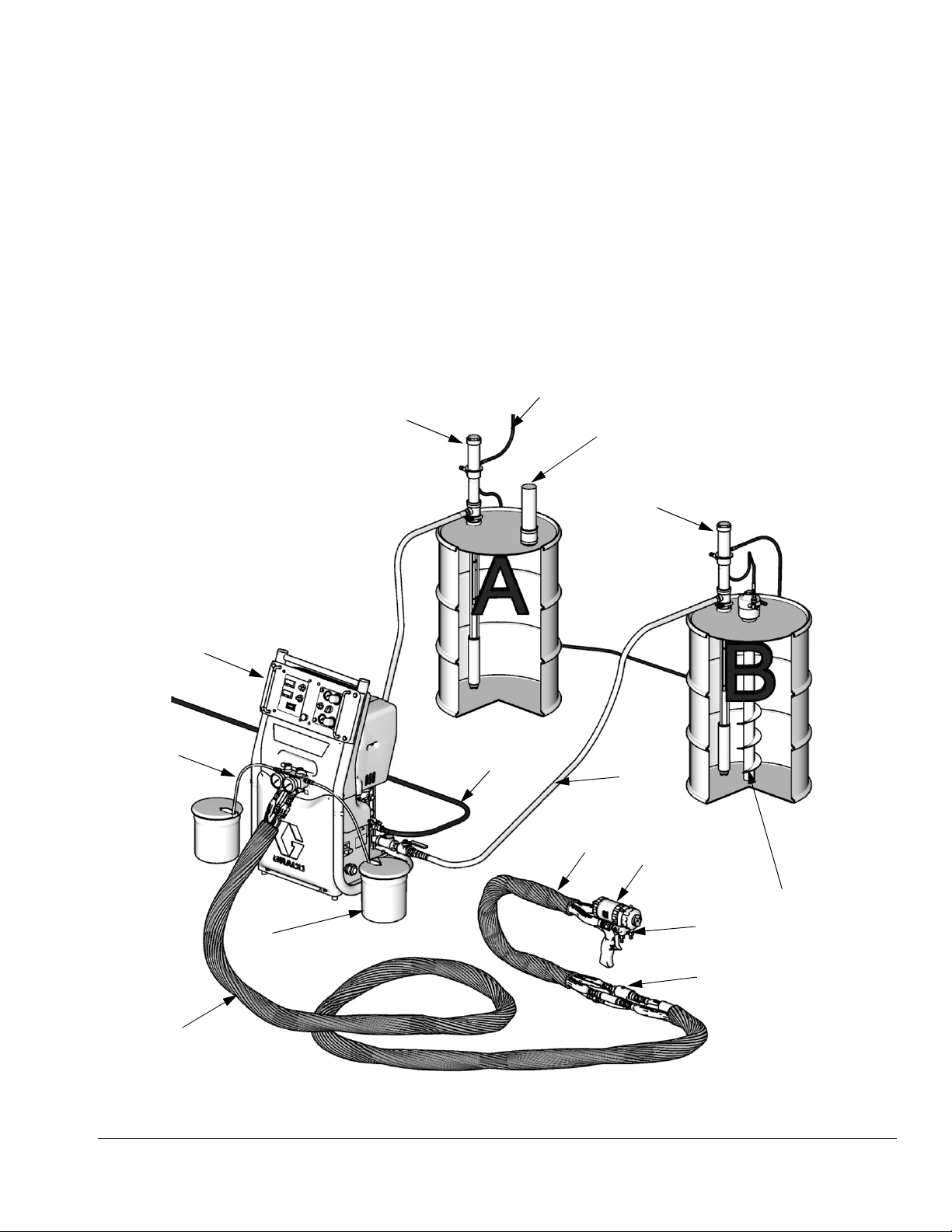
Typical Installation, without Circulation
Key for FIG. 1
Typical Installation
A Reactor Proportioner
B Heated Hose
C Fluid Temperature Sensor (FTS)
D Heated Whip Hose
E Fusion Spray Gun
F Proportioner and Gun Air Supply Hose
G Feed Pump Air Supply Lines (3/8 in. (76 mm) ID min.
K
A
H Waste Containers
J Fluid Supply Lines (217382)
K Feed Pumps
L Agitator
M Desiccant Dryer
N Bleed Lines/Over Pressure Relief
P Gun Fluid Manifold
G
M
K
N
F
J
D
E
L
H
P
C*
B
ti11572a
* Shown exposed for clarity. Wrap with tape during operation.
FIG. 1: Typical Installation, without Circulation
311882T 5
Page 6
Typical Installation
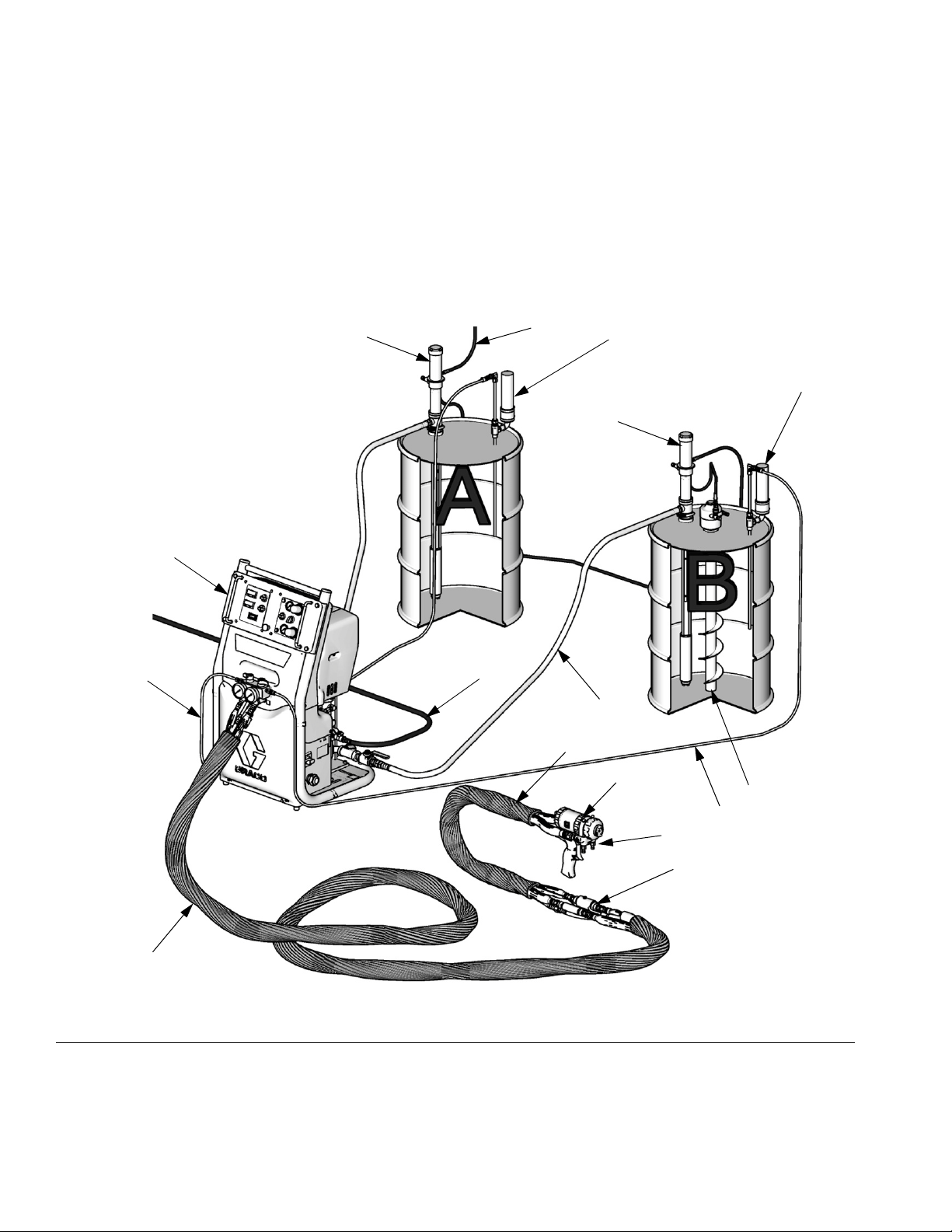
Typical Installation, with Circulation
Key for FIG. 2
A Reactor Proportioner
B Heated Hose
C Fluid Temperature Sensor (FTS)
D Heated Whip Hose
E Fusion Spray Gun
F Proportioner and Gun Air Supply Hose
A
G Feed Pump Air Supply Lines (3/8 in. (76 mm) ID min)
J Fluid Supply Lines
K Feed Pumps
L Agitator
M Desiccant Dryer
N Recirculation/Over Pressure Relief Return Hoses
P Gun Fluid Manifold
K
G
M
M
K
N
B
FIG. 2: Typical Installation, with Circulation
F
J
D
E
L
N
P
C*
ti11571a
* Shown exposed for clarity. Wrap with tape during operation.
6 311882T
Page 7
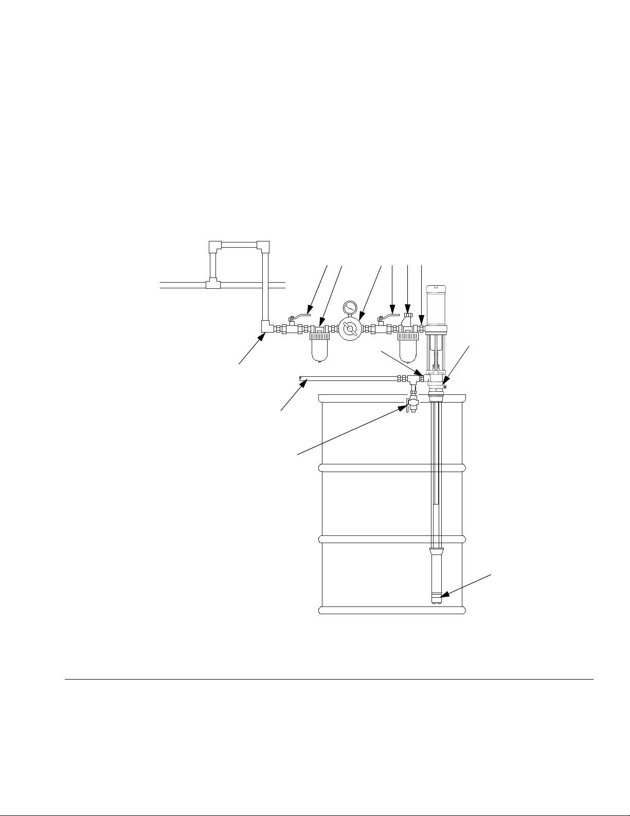
Typical Installation for Lubrication Applications
Key for FIG. 3
Typical Installation
A Pump Air Regulator
B Air Line Lubricator
C Air Line Filter
D Bleed-Type Master Air Valve (required, for pump)
E Fluid Drain Valve (required)
F Bung Adapter
G
H
G Grounded Air Hose
H Grounded Fluid Hose
J Pump Fluid Inlet
K 1/4 npt(f) Pump Air Inlet
L 3/4 npt(f) Pump Fluid Outlet
C
D
AB
K
D
L
F
E
FIG. 3: Typical Installation for Lubrication Applications
J
J
01349
311882T 7
Page 8

Installation
Installation
A bleed-type master air valve (D) and a fluid drain
valve (E) are required in your system, to help reduce
the risk of serious injury, including splashing fluid in
the eyes or on the skin, and injury from moving parts
when you are adjusting or repairing the pump.
The bleed-type master air valve (D) relieves air
trapped between this valve and the pump after the
pump is shut off. Trapped air can cause the pump to
cycle unexpectedly and result in serious injury,
including amputation. Install the valve close to the
pump.
The fluid drain valve (E) helps relieve pressure in the
displacement pump, hose, and dispensing valve
when shutting off the pump. Actuating the dispensing
valve to relieve pressure may not be sufficient, especially if there is a clog in the hose or the dispensing
valve.
Fluid Line Accessories
A fluid drain valve (E) is required in your system to
relieve fluid pressure in the hose and gun (see the
WARNING on left). Install the drain valve so that it
points down and the handle points up when the valve is
opened.
System Accessories
To ensure maximum pump performance, be sure that all
accessories used are properly sized to meet your system’s requirements. See Accessories, page 20.
Air Line Accessories
Install the following accessories in the order shown in
the Typical Installation for Lubrication Applications,
using adapters as necessary:
An air line lubricator (B) provides automatic air motor
lubrication.
A bleed-type master air valve (D) is required in your
system to relieve air trapped between it and the air
motor when the valve is closed (see the WARNING on
left). Be sure the bleed valve is easily accessible from
the pump, and is located downstream from the air regulator.
An air line filter (C) to remove harmful dirt and moisture
from the compressed air supply.
A second bleed-type air valve (D) isolates the air line
accessories for servicing. Locate upstream from all
other air line accessories.
8 311882T
Page 9

Setup
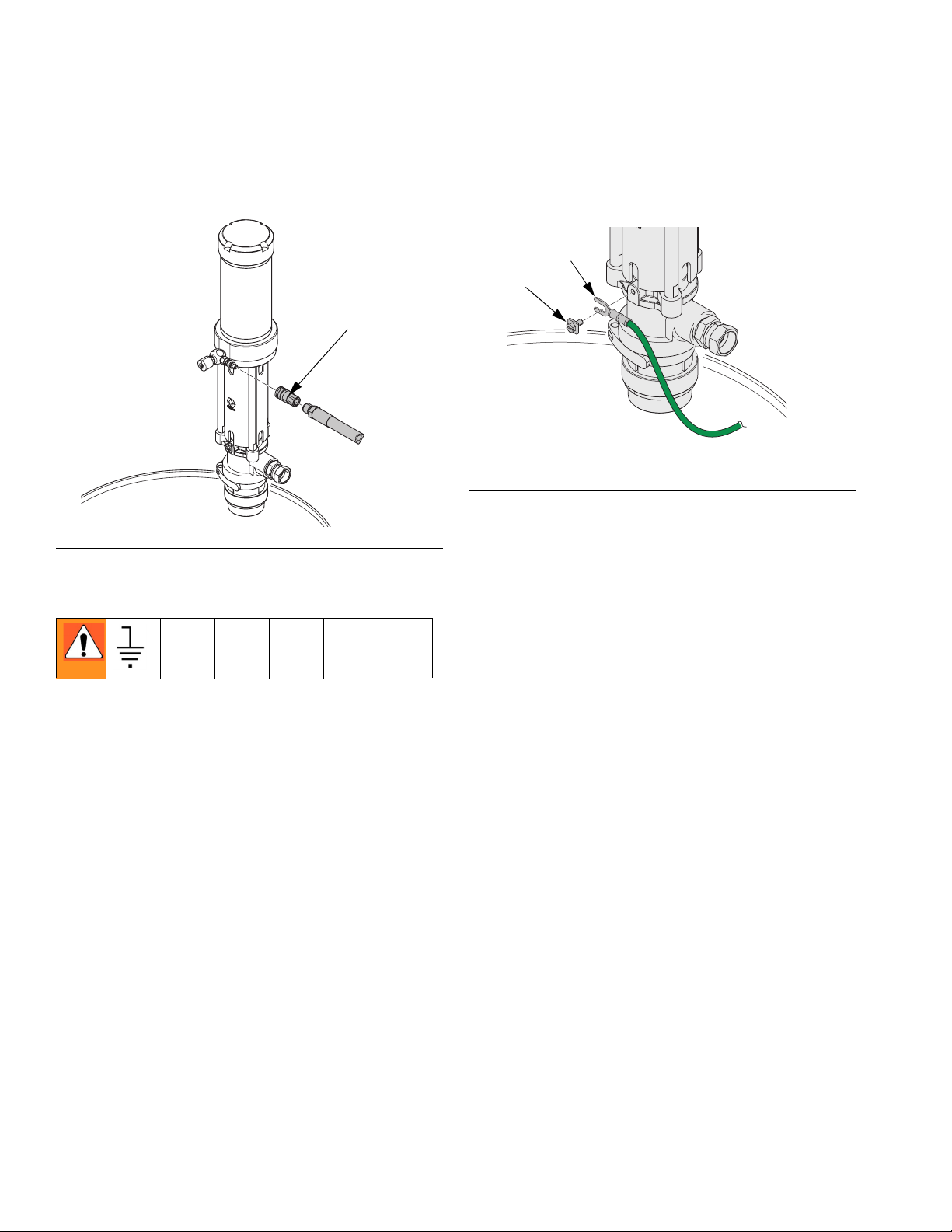
Setup
1. Apply thread sealant to the male threads of the air
needle valve (48) and the quick disconnect fitting
(49) and install. See F
1
Apply thread sealant
48
IG
. 4
F
1
1
49
IG
. 4
WLD
3. Use labels (70) provided to identify the appropriate
pump for your material. See F
IG
. 5.
FIG. 6
4. Lubricate the bung adapter inside diameter and
mounting threads. Ensure the gasket is in place and
screw the bung adapter (51) securely into the bunghole of the drum. Insert the pump through the
adapter and lock it in place. See F
IG
. 7.
2. Apply thread sealant to the male outlet fitting (not
supplied) and insert into the outlet port. See F
Apply thread sealant
1
IG
. 5.
1
1
2
F
IG
. 7
Lubricate threads
51
2
IG
. 5
F
311882T 9
Page 10
Setup
5. Install air line (3/8 in. (76 mm) ID minimum) with
quick disconnect air coupler (52) provided. See F
8.
52
F
IG
. 8
IG
1. Pump: Connect Ground Wire (Y) to grounding
.
screw (72) and tighten the screw securely. See F
9. Connect the other end of the wire to a true earth
ground. Make certain to comply with all National,
State, and Local Electrical Codes.
Y
72
WLD
FIG. 9
2. Air compressor: according to manufacturer’s recom-
mendations.
IG
.
Grounding the System
To reduce the risk of static sparking, ground the pump
and all other equipment used or located in the pumping
area. Check your local electrical code for detailed
grounding instructions for your area and type of
equipment. Ground all of this equipment.
3. Fluid hoses: use only grounded hoses with a maximum of 300 ft (91 m) combined hose length to
ensure grounding continuity. Refer to Hose Grounding Continuity.
4. Dispensing valve: grounding is obtained through
connection to a properly grounded fluid hose and
pump.
5. Object being sprayed: according to local code.
6. Fluid supply container: according to local code.
7. All solvent pails used when flushing, according to
local code. Use only metal pails, which are conductive. Do not place the pail on a non–conductive surface, such as paper or cardboard, which interrupts
the grounding continuity.
8. To maintain grounding continuity when flushing or
relieving pressure, always hold a metal part of the
spray gun/dispensing valve firmly to the side of a
grounded metal pail, then trigger the gun/valve.
10 311882T
Page 11
Operation
Operation
Pressure Relief Procedure
Trapped air can cause the pump to cycle unexpectedly, which could result in serious injury from splashing
or moving parts.
1. Engage trigger lock.
2. Close the bleed-type master air valve.
3. Disengage the trigger lock.
4. Hold a metal part of the dispense valve firmly to a
grounded metal pail. Trigger the valve to relieve
pressure.
5. Engage the trigger lock.
6. Open all fluid drain valves in the system, having a
waste container ready to catch drainage. Leave
drain valve(s) open until you are ready to dispense
again.
7. If you suspect the nozzle or hose is clogged or that
pressure has not been fully relieved after following
the steps above, VERY SLOWLY loosen the hose
end coupling to relieve pressure gradually, then
loosen completely. Clear hose or nozzle obstruction.
Flushing
Trapped air can cause the pump to cycle unexpectedly, which could result in serious injury from splashing
or moving parts.
1. Follow Pressure Relief Procedure, page 11.
2. Place suction tube in grounded metal drum containing cleaning fluid.
3. Set pump to lowest possible fluid pressure, and start
pump.
4. Hold a metal part of the dispense valve firmly to a
grounded metal pail. Trigger the dispense valve
until clean solvent dispenses.
5. Remove valve from hose.
6. Follow Pressure Relief Procedure, and remove
fluid filter and soak in solvent. Replace filter cap.
Daily Startup
1. Verify that the air needle valve is closed.
2. Connect the air line quick disconnect coupler to the
transfer pump
3. Turn on the main air supply.
4. Slowly open the air needle valve until the transfer
pump runs slowly.
5. Use the air needle valve to control the pump speed.
Caution
Never allow the pump to run dry of the fluid being
pumped. A dry pump will quickly accelerate to a high
speed and could cause personal injury and/or damage to the pump. If the pump accelerates quickly or
starts running too fast, stop it immediately and check
the fluid supply. If the supply container is empty or air
has been pumped into the lines, refill the container
and prime the pump and the lines with fluid, or flush
and leave it filled with a compatible solvent. Be sure to
eliminate all air from the fluid system.
Do not attempt to operate pump unless it is securely
mounted in a drum.
• Flush at the lowest pressure possible. Check
connectors for leaks and tighten as necessary.
• Flush with a fluid that is compatible with the
fluid being dispensed and the equipment wetted
parts.
311882T 11
Daily Shutdown
1. Disconnect air line coupler.
2. When air pressure is bled off, close the air line needle valve.
Page 12

Air Motor Repair
Air Motor Repair
CAUTION
Air valve assembly has changed to series B for
improved performance. Parts are not interchangeable
between series A and B air motor. Series A air valves
can be upgraded to series B with kit 262042.
1. Remove cap (1), cylinder (4), and square gaskets
(3*). Inspect all parts, including spring under cap
(not shown in F
necessary. See F
IG
. 10) for damage and replace if
IG
. 10. Unscrew by hand or use a
chain wrench to prevent distortion of the cylinder’s
shape.
1
*3
4
*3
WLD
F
IG
. 10
NOTE: Cap (1) was replaced with a spring stop assem-
bly for improved spring life. Existing pumps can be
upgraded with Kit 24T043.
NOTE: Series A air motors have thin, flat, white seals in
air valve. Series B (and later) air motors have thicker
black seals in the air valve.
2. Series A air motors only: Loosen set screw (18) and
unscrew air valve (5). If necessary to assist turning,
wedge a screwdriver blade between the screw
heads and the hex cap of air valve (5). Discard
items 5, 13, 15, and 18. See F
*15
*13
18
IG
. 11.
5
FIG. 11: Series A Air Valve
3. Series B (and later Air Motors): Unscrew air
valve (5). If necessary to assist turning, wedge a
screwdriver blade between the screw heads and the
hex cap of the air valve (5). Inspect o-rings (13* and
15*) for damage and replace if necessary. Ensure
o-ring (13*) is correctly positioned and not pinched.
See F
IG
. 12.
*15
5
*13
WLD
F
IG
. 12 Series B Air Valve
12 311882T
Page 13

Air Motor Repair
4. Align slot of shield (75) with piston hole and place
pin tool (69) in piston hole to prevent piston from
turning. Use second pin tool (69) to unscrew piston
cap (17) and separate from piston (21) to expose
dowel pin (19). See F
69
21
69
IG
. 13.
17
75
WLD
F
IG
. 13
6. Slide air piston (21) out the top of the air motor base
(23). Remove o-ring (24*) from air motor base.
Inspect all parts, including the spring (22) in the air
motor base, for damage. See F
21
*24
22
23
IG
. 15.
WLD
FIG. 15
5. Remove dowel pin (19) and take piston cap (17) off
transfer shaft (20). Remove o-ring (50*) from piston
cap. Inspect all parts for damage. See F
17
19
*50
20
IG
. 14
F
WLD
IG
. 14.
311882T 13
Page 14

Pump Lower Repair
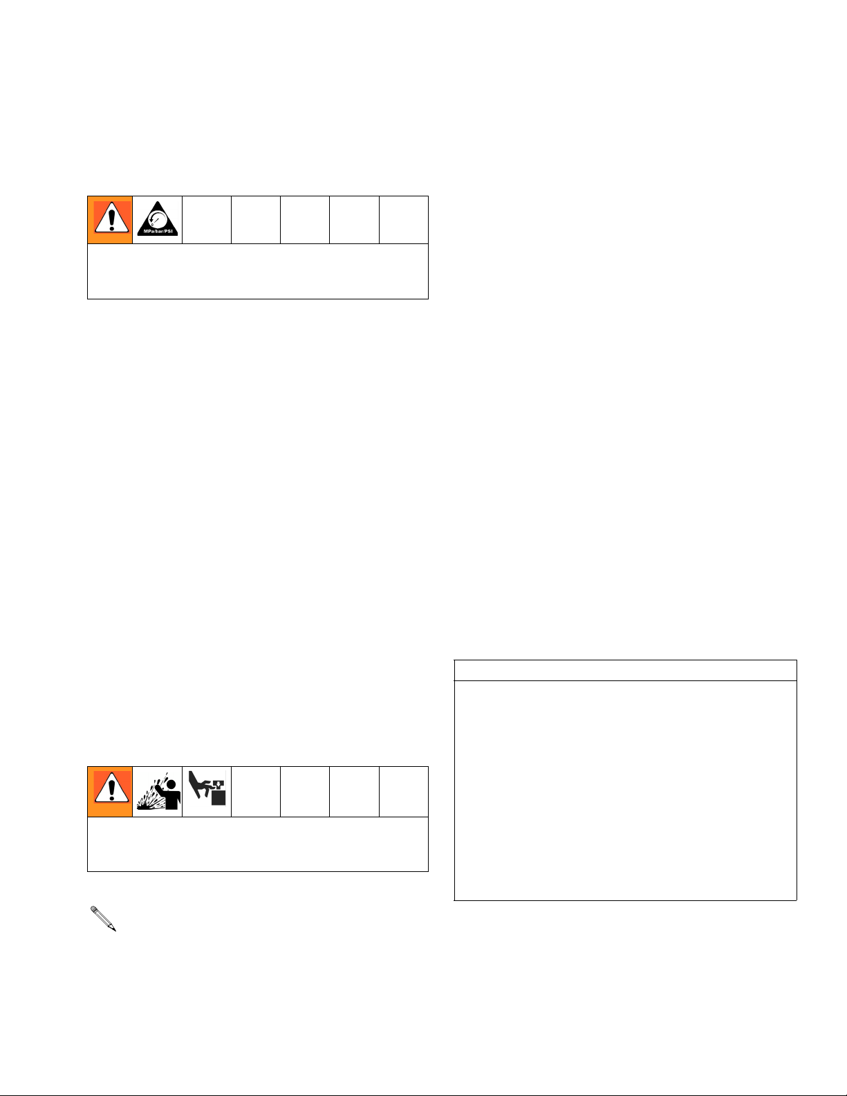
Pump Lower Repair
1. Use a chain wrench near the top of the suction tube
at the point indicated in F
the flats of the foot valve (45) to loosen the foot
valve from the suction tube (44). To prevent damage to the suction tube, do not remove the foot
valve until instructed to do so in step 3.
Apply chain wrench
approximately here
F
IG
. 16
IG
. 16, and a wrench on
44
2. With the foot valve still in place to support the suction tube, use a chain wrench near the bottom of the
suction tube at the point indicated in F
IG
. 17, to
loosen the suction tube (44) from the pump body
(34).
3. Remove the foot valve assembly from the suction
tube (44).
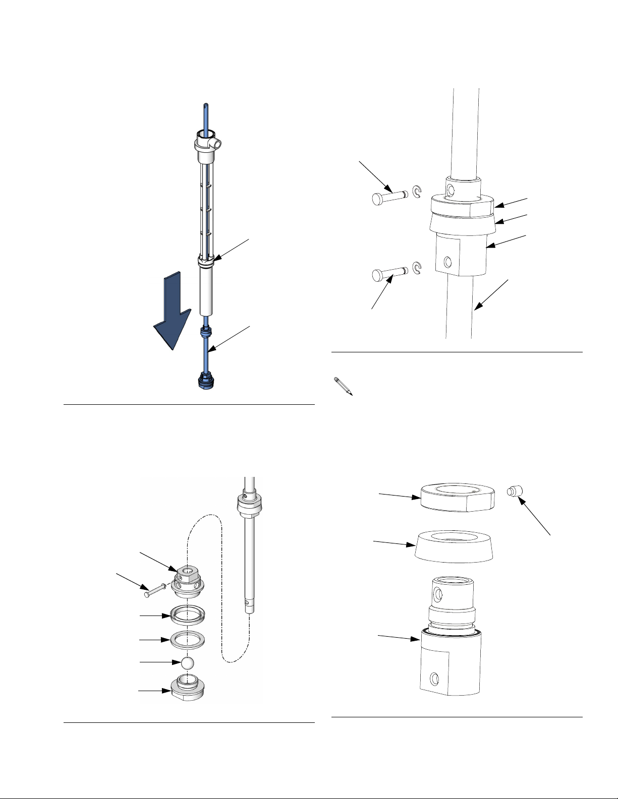
4. Remove retaining ring (46), snap ring (47), ball (71),
and o-ring (38*) from foot valve (45). Inspect all
parts for damage. See F
IG
. 17.
5. Remove suction tube (44) from pump body (34).
See F
IG
. 18.
6. Inspect o-ring (38) on pump body and suction tube
IG
for damage. See F
38
Apply chain wrench
approximately here
. 18.
34
NOTE: When removing the suction tube, be
very careful not to bend, dent, or damage it. To
avoid damage, use the chain wrench only at the
top and bottom of the suction tube as indicated
in F
IG
. 16 and FIG. 17. Do not apply the wrench
to the middle of the suction tube.
46
47
71
*38
45
44
Apply chain wrench
approximately here
44
ti9976
FIG. 18
ti9903
IG
. 17
F
14 311882T
Page 15
Pump Lower Repair
7. Pull transfer shaft (20) out the bottom of pump body
(34). See F
IG
. 19.
34
20
9. Remove pins (55). See F
55
55
FIG. 21
IG
. 21.
36
35
54
74
r_311880_14e_fig21
ti9905
IG
. 19
F
8. Remove pin (56). Remove piston valve assembly.
Unscrew piston valve (43) from piston housing (53).
Remove wear ring (41*), u-cup (40*) and ball (42).
Inspect all parts for damage. See F
53
56
*40
Lip up
*41
42
IG
. 20.
NOTE: Series A and B pumps were equipped
with springs pins. In Series C pumps, these
pins were replaced with a solid clevis
pin (55, 56).
10. Loosen set screw (37) from collar (36). Remove collar from piston housing (54). Remove u-cup (35*).
Inspect all parts for damage. See F
36
*35
Lip down
54
IG
. 22.
37
43
IG
. 20
F
311882T 15
ti9904b
F
IG
. 22
r_311882_14e_fig22
Page 16

Pump Lower Repair
11. Unscrew mounting flange (26) from pump body
(34). Remove o-ring (32*) and PTFE gasket (33*)
from pump body (34). Inspect all parts for damage.
See F
IG
. 23.
NOTE: Align a bottom slot of the shield (75) and use
pin tool (69) to loosen the hex nut/packings from the
pump shaft.
34
26
*32
*33
13. Unscrew three fasteners (60) to remove the flange
(26) and tie-rods (25). Slide the guard (75) out.
Unscrew the tie rods (25) using the wrench flats at
the bottom.
25
75
26
WLD
F
IG
. 23
12. Remove hex nut (27) from mounting flange (26).
Remove female gland (30*), 2 PTFE packings (29*),
male gland (28*) and wiper (31*). Inspect all parts
for damage. See F
75
69
IG
. 25.
27
*30
*29
*28
*31
FIG. 24
WLD
60
Seal stack enlarged
to show detail.
WLD
FIG. 25
16 311882T
Page 17

Reassembly
Reassembly
To reassemble the pump lower and air motor, reverse
the steps on the preceding pages. Follow the torque
requirements listed in the Parts - Model 295616 drawing on page 18.
NOTE: See Air Motor Repair, step 3 and step 4
(F
IG
. 12) for special notes on reassembly.
Troubleshooting
Problem Cause Solution
The pump fails to operate Dirty or worn air motor. Clean, service
Inadequate air supply or restricted
lines.
Closed or clogged air valves. Open or clear the valves.
Clogged fluid hose or valve. Clear the hose or valves
Worn or damaged valves or seals. Service the valves or seals.
The pump operates, but the output is
low on both strokes.
The pump operates, but the output is
low on the downstroke.
The pump operates, but the output is
low on the upstroke.
Erratic or accelerated operation. Exhausted fluid supply. Refill the fluid supply and reprime the
Pump slowly moves after fluid shutoff
in downstroke.
Pump slowly moves after fluid shutoff
in upstroke.
Clogged fluid hose or valve. Clear the hose or valves.
Exhausted fluid supply. Refill the fluid supply and reprime the
Worn or damaged valves or seals. Service the valves or seals.
Held open or worn intake valve. Clear or service the valve.
Worn or damaged valves or seals. Service the valves or seals.
Held open or worn piston valve. Clear or service the valve.
Worn or damaged valves or seals. Service the valves or seals.
Broken air motor compression spring. Replace the spring.
Clogged or dirty intake valve check
ball.
Worn or damaged valves or seats. Install repair kit.
Clogged or dirty lower piston ball or
seat.
Worn or damaged valves or seats. Install repair kit.
Clean lines or increase the air supply
(see Technical Data).
pump.
pump.
Clean ball and seat.
Clean ball and seat.
311882T 17
Page 18

Parts - Model 295616
Parts - Model 295616
1
8
76
77
21
4
74
❄
56✓
✿
4
✿
*✿50
*3
2
22
53
40✓
34
23
4
8
24*
41✓
42✓
43
2
3*
25
6
5
19
5d
5a*
5c
5j*
5e
5b*
5h*
5f
5g
17
✿
60
*32
*30
*29
*28
72
6
75
27
31*
26
9
36
❄
20
❄
55
38✓
73✓
44
5
39
3
37
7
46
47
35✓
71
38✓
45
❄
54
4
WLE
5
51c
*33
1
Lubricate all o-rings and seals before and after assembly
2
Torque to 45-55 ft-lbs (61-74.5 N•m)
3
Torque to 30-40 ft-lbs (40.6-54.2 N•m)
4
Torque to 15-20 ft-lbs (20.3-27.1 N•m)
5
Torque to 10-12 ft-lbs (13.5-16.3 N•m)
6
Torque to 110-120 in-lbs (12.3-13.4 N•m)
7
Torque to 20-30 in-lbs (2.2-3.3 N•m)
8
Torque to 50-60 in-lbs (5.6-6.7 N•m)
9
Tighten 1/8 to 1/4 turn past finger-tight
51
Bung Adapter
✓51h
51b
✓51a
18 311882T
Page 19

Parts - Model 295616
Ref Part Description Qty
1‡ 16V524 CAP, air cylinder 1
2‡ 157630 SPRING, tapered 1
3‡* 120212 PACKING, square 2
4 24J528 CYLINDER, air motor 1
5✿ 262035 VALVE, air 1
5a* 15J539 GASKET, upper 1
5b* 121889 O-RING 3
5c 15J544 SPACER 3
5d 121610 SCREW 3
5e 16U730 CAP, air, valve 1
5f 15V554 HEAD, air valve 1
5g 15J546 DISK, air valve 1
5h* 160258 O-RING 1
5j* 722834 O-RING 1
17✿ CAP, air piston 1
19✿ 15J548 PIN, dowel 1
20❄ SHAFT, transfer 1
21 24J535 PISTON, air 1
22 15J551 SPRING, compression 1
23 24J529 BASE, air motor 1
24* 159846 O-RING (green) 1
25 15J553 ROD, tie 3
26 24J530 FLANGE, mounting 1
27 15J555 NUT, hex 1
28* 15J556 GLAND, packing, (male) 1
29* 15J557 V-PACKING, PTFE 2
30* 15J558 GLAND, packing, (female) 1
31* 15J559 WIPER, ROD 1
32* 15C638 O-RING, PTFE, encapsulated 1
33* 15J560 GASKET, PTFE 1
34 24J536 BODY, pump, 2:1 1
35✓ 15J562 PACKING, piston cup 1
36 15J563 COLLAR, retaining 1
37 101194 SCREW, set, socket head,
10-32 x .25 in. (6 mm)
38✓★ 106258 O-RING 2
39 24J534 CYLINDER, fluid 1
40✓ 15J565 PACKING, u-cup, PTFE 1
41✓ 15J566 RING, wear 1
42✓ 103462 BALL, outlet, sst, 3/4 in. (19 mm) 1
43 24J531 VALVE, piston 1
44 24J532 TUBE, suction 1
45 24J533 VALVE 1
46 120734 RING, retaining, internal 1
47 120735 RING, snap, e series 1
48† 206264 VALVE, needle 1
49† 169969 FITTING, air line 1
50*✿ 108832 O-RING 1
51 253146 ADAPTER, bung
(includes 51a-51g)
51a✓ 120998 O-RING, fluoroelastomer 1
51b 24J526 ADAPTER 1
51c 234188 CLAMP, hopper 1
51h✓ 120207 O-RING; inner (brown) 1
52† 114558 COUPLER, air line 1
53 15J570 HOUSING, piston 1
54❄ PISTON, upper 1
55✓❄ 120294 PIN, clevis, 3/16 in. x 3/4 in. 2
Ref Part Description Qty
56✓ 120295 PIN, clevis, 3/16 in. x 1-1/4 in. 1
60 120348 SCREW, cap, socket head
1/4-20 x 1 in. (25 mm)
69† 15H197 TOOL, pin 2
70† 15K008 LABEL, material identification. 1
71✓ 107167 BALL, intake, sst, 1 in. (25 mm) 1
72 116343 SCREW, ground 1
73✓ 113944 O-RING 1
74❄ SHAFT, transfer, lower 1
75 24V858 GUARD 1
76‡ 111819 O-RING 1
77‡ 16V523 PIN, spring stop 1
* Parts included in Upper Seal Repair Kit 262034 (not
sold separately).
✓ Parts included in Lower Seal Repair Kit 247883.
NOTE: Seal Repair Kit 24X056 includes all parts in
kit 262034 and kit 247883. The spring pins (55, 56)
originally supplied in series A and B pumps have
been upgraded to a solid clevis pin for improved reliability.
❄ Parts included in repair kit 256560
NOTE: The pump shaft originally supplied in series A
pumps has been upgraded to a multi-piece assembly
for better sealing and serviceability. Pumps can be
upgraded with repair kit 256560.
✿ Parts included in repair kit 262042
NOTE: The air valve originally supplied in series A
1
pumps can be upgraded with kit 262042.
† Indicates parts not shown, 48, 49, 52, 69, 70
(shipped loose)
★ O-rings included in Tube Extension Kit 24N451.
‡ Parts included in air cap 24T043
NOTE: The cylinder cap has been upgraded with
spring stop for improved reliability. Existing pumps
can be upgraded with Kit 24T043.
NOTE: The T2 can be adapted for use in 250 gallon
(946 liter) totes. Tube Extension 24N451 increases the
length by 6.25 in. (165 mm) to reach material in the bot-
1
tom of larger totes.
3
311882T 19
Page 20

Accessories
Accessories
Grounding Clamp
Qty
Part Description
103538 CLAMP, ground 1
Bleed-Type Master Air Valve
300 psi (2.1 MPa, 21 bar) Maximum Working
Pressure
Qty
Part Description
107142 VALVE, ball, vented; 1/2 npt(m) inlet x 1/2
npt(f) outlet
Air Line Filter
Air Line Lubricator
250 psi (1.7 MPa, 17.5 bar) Maximum Working
Pressure
.
Part Description
214848 LUBRICATOR, air line; 8 oz (0.24 liter)
bowl capacity; 1/2 npt(f) inlet and outlet
Air Line Filter and Regulator
180 psi (1.3 MPa, 13 bar) Maximum Working
.
Pressure
1
Part Description
202660 FILTER, air; includes gauge and two 1/4
npt(m) outlet valves, 50 micron filter element with 100 mesh inlet strainer; 1/2
npt(f) inlet; flow rate is over 50 scfm (1.4
3
m
/min).
Qty
.
1
Qty
.
1
250 psi (1.7 MPa, 17.5 bar) Maximum Working
Pressure
Qty
Part Description
106149 FILTER, air line; 1/2 npt(f) inlet and outlet 1
20 311882T
.
01355
Page 21

Accessories
Air Regulator and Gauge
300 psi (2.1 MPa, 21 bar) Maximum Working
Pressure
Part Description
202156 REGULATOR, air; 0-200 psi (0-14 bar)
regulated pressure range; 3/8 npt(f) inlet
and outlet
Qty
Fluid Drain Valve
500 psi (3.5 MPa, 35 bar) Maximum Working
Pressure
.
Part Description
1
208630 VALVE, ball; 1/2 npt(m) x 3/8 npt(f);
for non-corrosive fluids; carbon
steel and PTFE
237534 VALVE, ball; 3/8 npt(m) x 3/8 npt(f);
for corrosive fluids; SST and PTFE
Qty
.
1
1
311882T 21
Page 22

Technical Data
Technical Data
T2 2:1 Ratio Transfer Pump
US Metric
Pressure Ratio 2.25:1
Max fluid working pressure 405 psi 2.8 MPa, 28 bar
Maximum Air inlet pressure 180 psi 1.2 MPa, 12 bar
Max Output Flow (continuous)
Max Output Flow (intermittent 7.5 GPM 28 lpm
Pump cycles per 1 gallon (3.8 liters) 15.9
Maximum recommended pump speed for con-
tinuous operation
Gallons (liters) per pump cycle 0.063 gal. 0.24 l
Air consumption See performance chart
Maximum Ambient temperature 120° F 50° C
Maximum Fluid Temperature 190° F 88° C
Wetted parts Stainless Steel, PTFE
Air Inlet Port 1/4 npt(f)
Fluid Outlet Port 3/4 npt(f)
Weight 21.0 lb 9.5 kg
Sound Pressure 88.7 dB(A) at 80 psi (.55 MPa, 5.5 bar)
Sound Power, per ISO 9614-2 96.8 dB(A) at 80 psi (.55 MPa, 5.5 bar)
5.0 GPM
100 cycles per min (150 cycles per min intermittent)
20 lpm
Dimensions
1/4 npt inlet
33.7 in. (85.6 cm)
3/4 npt outlet
54 in. (137.2 cm)
WLD
22 311882T
Page 23

Performance Chart
Technical Data
Calculate Fluid Outlet Pressure (black
curves)
To calculate fluid outlet pressure (MPa/bar/psi) at a specific fluid flow (lpm/gpm) and operating air pressure
(MPa/bar/psi), use the following instructions and pump
data chart.
1. Locate desired fluid flow along bottom of chart.
2. Follow vertical line up to intersection with selected
air pressure curve (black). Follow horizontally left to
read fluid outlet pressure.
Key: Air Pressure
A 180 psi (1.2 MPa, 12.4 bar)
B 100 psi (0.7 MPa, 7 bar)
C 70 psi (0.5 MPa, 4.8 bar)
D 40 psi (0.3 MPa, 2.8 bar)
500
(3.5, 34.5)
400
(2.8, 28)
300
(2.1, 21)
200
(1.4,14)
100
(0.7, 7)
Outlet Pressure in PSI (MPa, bar)
0.0
0.0 0.5 1.0 1.5 2.0 2.5 3.0 3.5 4.0 4.5
Calculate Pump Air Consumption (gray
curves)
To calculate pump air consumption (m3/min or scfm) at
a specific fluid flow (lpm/gpm) and air pressure
(MPa/bar/psi), use the following instructions and pump
data chart.
1. Locate desired fluid flow along bottom of chart.
2. Follow vertical line up to intersection with selected
air pressure curve (gray). Follow horizontally right to
read air consumption.
40.00
(1.1)
35.00
(1.0)
30.00
(0.8)
Air Consumption in SCFM (m
A
25.00
(0.7)
20.00
(0.6)
B
C
D
D
A
15.00
(0.4)
B
C
10.00
(0.3)
5.00
(0.1)
0.00
(17.1)(15.2)(13.3)(9.5)(5.7)(1.9) (11.4)(7.6)(3.8)
3
/min)
Fluid Flow in gpm (lpm)
311882T 23
Page 24

Graco Standard Warranty
Graco warrants all equipment referenced in this document which is manufactured by Graco and bearing its name to be free from defects in
material and workmanship on the date of sale to the original purchaser for use. With the exception of any special, extended, or limited warranty
published by Graco, Graco will, for a period of twelve months from the date of sale, repair or replace any part of the equipment determined by
Graco to be defective. This warranty applies only when the equipment is installed, operated and maintained in accordance with Graco’s written
recommendations.
This warranty does not cover, and Graco shall not be liable for general wear and tear, or any malfunction, damage or wear caused by faulty
installation, misapplication, abrasion, corrosion, inadequate or improper maintenance, negligence, accident, tampering, or substitution of
non-Graco component parts. Nor shall Graco be liable for malfunction, damage or wear caused by the incompatibility of Graco equipment with
structures, accessories, equipment or materials not supplied by Graco, or the improper design, manufacture, installation, operation or
maintenance of structures, accessories, equipment or materials not supplied by Graco.
This warranty is conditioned upon the prepaid return of the equipment claimed to be defective to an authorized Graco distributor for verification of
the claimed defect. If the claimed defect is verified, Graco will repair or replace free of charge any defective parts. The equipment will be returned
to the original purchaser transportation prepaid. If inspection of the equipment does not disclose any defect in material or workmanship, repairs
will be made at a reasonable charge, which charges may include the costs of parts, labor, and transportation.
THIS WARRANTY IS EXCLUSIVE, AND IS IN LIEU OF ANY OTHER WARRANTIES, EXPRESS OR IMPLIED, INCLUDING BUT NOT
LIMITED TO WARRANTY OF MERCHANTABILITY OR WARRANTY OF FITNESS FOR A PARTICULAR PURPOSE.
Graco’s sole obligation and buyer’s sole remedy for any breach of warranty shall be as set forth above. The buyer agrees that no other remedy
(including, but not limited to, incidental or consequential damages for lost profits, lost sales, injury to person or property, or any other incidental or
consequential loss) shall be available. Any action for breach of warranty must be brought within two (2) years of the date of sale.
GRACO MAKES NO WARRANTY, AND DISCLAIMS ALL IMPLIED WARRANTIES OF MERCHANTABILITY AND FITNESS FOR A
PARTICULAR PURPOSE, IN CONNECTION WITH ACCESSORIES, EQUIPMENT, MATERIALS OR COMPONENTS SOLD BUT NOT
MANUFACTURED BY GRACO. These items sold, but not manufactured by Graco (such as electric motors, switches, hose, etc.), are subject to
the warranty, if any, of their manufacturer. Graco will provide purchaser with reasonable assistance in making any claim for breach of these
warranties.
In no event will Graco be liable for indirect, incidental, special or consequential damages resulting from Graco supplying equipment hereunder, or
the furnishing, performance, or use of any products or other goods sold hereto, whether due to a breach of contract, breach of warranty, the
negligence of Graco, or otherwise.
FOR GRACO CANADA CUSTOMERS
The Parties acknowledge that they have required that the present document, as well as all documents, notices and legal proceedings entered into,
given or instituted pursuant hereto or relating directly or indirectly hereto, be drawn up in English. Les parties reconnaissent avoir convenu que la
rédaction du présente document sera en Anglais, ainsi que tous documents, avis et procédures judiciaires exécutés, donnés ou intentés, à la suite
de ou en rapport, directement ou indirectement, avec les procédures concernées.
Graco Information
For the latest information about Graco products, visit www.graco.com.
TO PLACE AN ORDER, contact your Graco distributor or call to identify the nearest distributor.
Phone: 612-623-6921 or Toll Free: 1-800-328-0211 Fax: 612-378-3505
All written and visual data contained in this document reflects the latest product information available at the time of publication.
GRACO INC. AND SUBSIDIARIES • P.O. BOX 1441 • MINNEAPOLIS MN 55440-1441 • USA
Copyright 2007, Graco Inc. All Graco manufacturing locations are registered to ISO 9001.
Graco reserves the right to make changes at any time without notice.
For patent information, see www.graco.com/patents.
Original instructions. This manual contains English. MM 311882
Graco Headquarters: Minneapolis
International Offices: Belgium, China, Japan, Korea
www.graco.com
Revision T, October 2014
 Loading...