

Page 1
Instructions
Pump Kit for
X5, X7, LTS 15 and LTS 17 Airless Sprayers
This manual contains kit installation instructions only
Pump Replacement Kit: 289650
Important Safety Instructions
For detailed sprayer information and warnings, see Operation manuals
312001 or 313034 included with Magnum sprayers.
Pressure Relief Procedure
To help prevent injection injuries, follow this
procedure when you stop spraying and
before you service or clean the sprayer,
remove parts, or repair leaks.
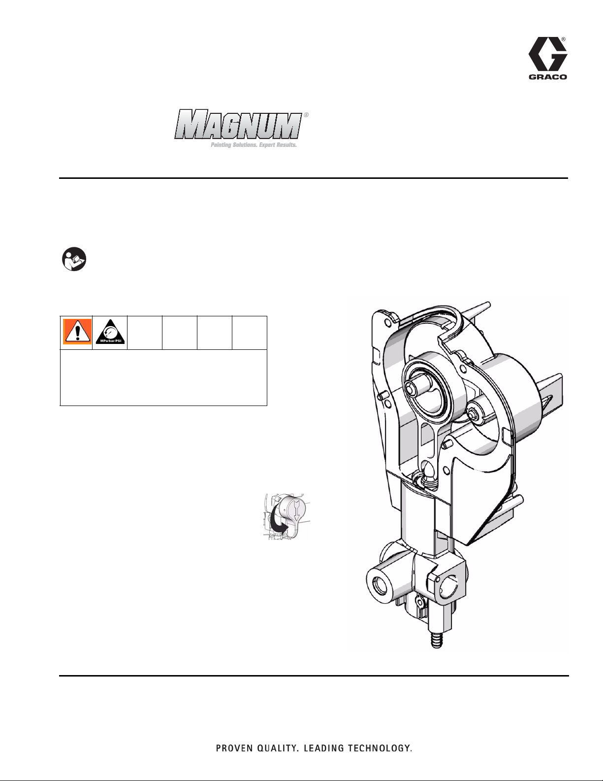
1. Turn power switch OFF. Unplug sprayer.
2. Turn Spray/Prime valve to PRIME to relieve pressure. Turn
pressure control knob left (counterclockwise) to minimize
pressure.
312932A
3. Trigger gun.
4. Put trigger safety in safety ON position.
NOTE: Leave Spray/Prime valve in the PRIME
position until you are ready to spray again.
If you suspect that the spray tip or hose is completely clogged
or that pressure has not been fully relieved after following the
steps above, VERY SLOWLY loosen the tip guard retaining nut
or hose end coupling to relieve pressure gradually. Then
loosen it completely. Clear the tip or hose obstruction.
ti11868a
ti11858a
Page 2
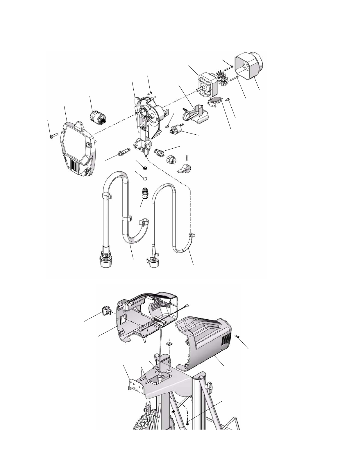
Pump Replacement Kit 289650
E
ph
mm
R
sc
P
C
Z
mm
gnd
F
cs
V
T
pv
ov
bt
bl
iv
ti11859a
W
U
L
K
H
E
ps
N
pb
G
D
ti11860a
2 312932A
Page 3

Pump Replacement
Disassembly
1. Unplug electrical cord and Relieve Pressure (see
page 1 or Operation manual 312001).
2. Remove hoses suction tube (W) and drain tube (U).
3. Remove and save inlet valve (iv), outlet (ov), ball (bl)
and ball stop (bt).
4. X7 and LTS 17 Only: Remove underside shroud
mounting screw (D).
5. Remove 4 side shroud screws (E) (T-20 Torx).
6. Remove 4 front cover screws (F) (T-30 Torx).
7. Remove right shroud (G).
8. Disconnect power cord connectors (H) from
ON/OFF switch (L).
9. Remove left shroud (K).
10. Remove 2 pump housing mounting screws (ps). Be
sure to support pump housing (ph).
11. Remove pump housing (ph). X7 and LTS 17 Only:
Pull power cord (N) through opening in pump housing mounting bracket (pb). Remove ground screw
(gnd) from pump housing (ph).
12. Remove all connectors from control board (T).
13. Remove control board mounting screw (cs).
Remove and save control board (T).
14. Unclip tab and remove AutoPrime solenoid cover
(sc).
15. Remove and save pressure control (P) and prime
valve (pv) and Autoprime (V) valve.
16. Remove motor cover (Z) from motor (R) and save.
Remove and save 2 motor mounting screws (mm).
Remove and save motor (R).
Assembly
1. Assemble new pump housing (ph) to front cover (C).
Insert 4 screws (E) and torque to 25 to 35 in-lb (2.8
to 4.0 N•m).
2. With motor thermal switch facing up, assemble
motor (R) to pump housing (ph) using 2 motor
mounting screws (mm). Rotate fan slightly to
engage teeth. Torque to 20 to 25 in-lb (2.3 to 2.8
N•m).
3. Assemble motor cover (Z) to motor (R).
4. Assemble pressure control (P) to pump housing
(ph). Torque to 140 to 160 in-lb (16 to 18 N•m).
5. Assemble prime valve (pv) to pump housing (ph).
Torque to 160 to 180 in-lb (18.1 to 20.3 N•m).
6. Assemble Autoprime solenoid (V) into pump housing. Torque to 200 to 240 in-lb (22.6 to 27.1 N•m).
Assemble Autoprime cover (sc).
7. Assemble control board (T) with control board
mounting screw (cs). Torque to 25 to 35 in-lb (2.8 to
4.0 N•m).
8. Assemble outlet valve (ov). Torque to 320 to 380
in-lb (36.2 to 42.9 N•m).
9. Assemble ball stop (bt), ball (bl), and inlet valve (iv).
Torque to 200 to 240 in-lb (22.6 to 27.1 N•m).
10. Install pump housing (ph) and 2 pump housing
mounting screws (ps) onto pump housing mounting
bracket (pb). Torque to 110 to 120 in-lb (12.4 to 13.6
N•m).
11. Reattach power cord ground lead to pump housing
(ph) with green ground screw (gnd).
12. Reconnect all connectors to control board (T) (see
Wiring Diagram on following page).
17. Remove 4 screws (E) holding pump housing (ph) to
front cover (C).
18. Arrange pump housing (ph) and front cover (C) so
front cover is on the top.
19. Remove front cover (C).
312932A 3
13. Attach power cord connectors (H) to power switch
and install left shroud (K).
14. X7 and LTS 17 Only: Route power cord (N) through
opening in pump housing mounting bracket (pb).
15. Install power cord (N) into recess on left shroud (K).
16. Install right shroud (G).
17. Install 4 side shroud screws (E) (T-20 Torx). Torque
to 20 to 25 in-lb (2.3 to 2.8 N•m).
18. Install 4 front cover screws (F) (T-30 Torx). Torque to
26 to 32 in-lb (2.9 to 3.6 N•m).
19. X7 and LTS 17 Only: Install underside shroud
mounting screw (D). Torque to 25 to 35 in-lb (2.8 to
3.9 N•m).
Page 4

Wiring Diagram
/./&&
37)4#(
0/7%2#/2$
",!#+7)2%
02%3352%
37)4#(
!54/02)-%
!&53%
7)2).'$)!'2!-
",!#+
-/4/2
,%!$
0/7%2#/2$
7()4%7)2%
7()4%
"/!2$7)2%
#(!33)3
'2/5.$
0/7%2#/2$
'2%%.7)2%
",!#+
-/4/2
,%!$
Thermal Switch
1
1
When assembling motor to pump housing, make sure
Thermal Switch is positioned on top as shown above.
All written and visual data contained in this document reflects the latest product information available at the time of publication.
Graco reserves the right to make changes at any time without notice.
This manual contains English. MM 312932
Graco Headquarters: Minneapolis
International Offices: Belgium, China, Japan, Korea
GRACO INC. P.O. BOX 1441 MINNEAPOLIS, MN 55440-1441
Copyright 2008, Graco Inc. is registered to I.S. EN ISO 9001
www.graco.com
Copyright 03/2008
 Loading...