

Page 1
Instructions -- Parts List
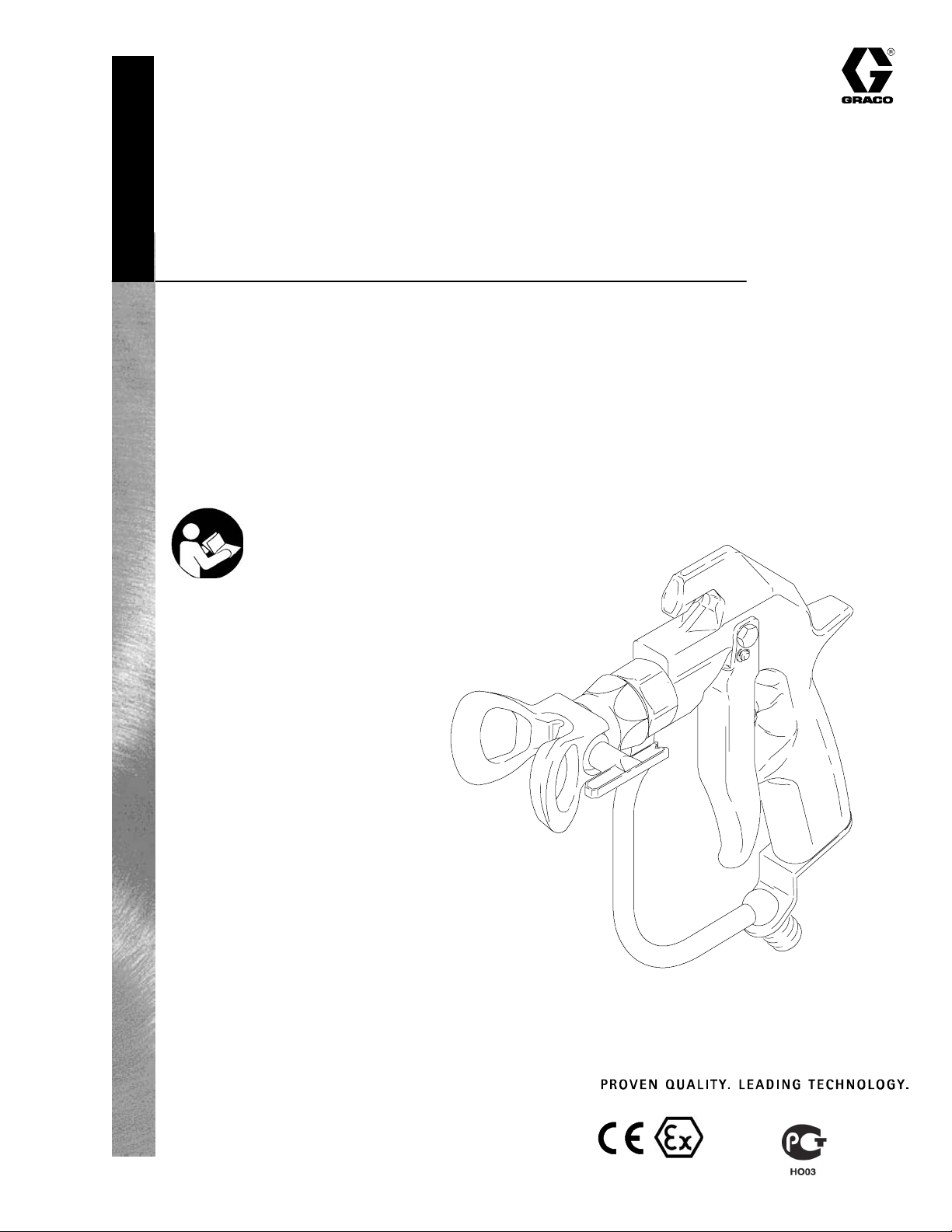
Texture Airless Spray Gun
27.6 MPa (276 bar, 4000 psi) Maximum Working Pressure
Part No. 241705, Series B
Includes a RACr Tip Guard and LTX531 Switch Tipr
Part No. 289605 (Europe Only), Series B
Includes a RACr Tip Guard and HDA531 Switch Tipr
Important Safety Instructions
Read all warnings and instructions in this manual.
Save these instructions.
See page 2 for T able of Contents.
308491S
GRACO INC. P.O. BOX 1441 MINNEAPOLIS, MN 55440- 1441
Copyright 2002, Graco Inc. is registered to I.S. EN ISO 9001
03965
II 2 G
Page 2
Table of Contents
Symbols
Symbols 2.................................
Warnings 3.................................
Installation/Operation 5......................
System Requirements 5...................
Ground the System 5......................
How to Use the Gun Trigger Safety 5........
Pressure Relief Procedure 5................
HowtoUsetheGun 6.....................
How to Adjust the Spray Pattern 6...........
Care of the Spray Tip and Tip Guard 7.......
How to Flush the Gun 8....................
How to Check the Gun Diffuser Operation 9..
Service 10.................................
Parts 14...................................
Technical Data 15...........................
Dimensions 15..............................
Graco Phone Numbers 15....................
The Graco Warranty and Disclaimers 16.......
Warning Symbol
WARNING
This symbol alerts you to the possibility of serious
injury or death if you do not follow the instructions.
Caution Symbol
CAUTION
This symbol alerts you to the possibility of damage to
or destruction of equipment if you do not follow the
corresponding instructions.
3084912
Page 3
WARNING
WARNING
SKIN INJECTION HAZARD
Spray from the gun, leaks or ruptured components can inject fluid into your body and cause extremely serious injury, including the need for amputation. Fluid splashed in the eyes or on the skin
can also cause serious injury.
D Fluid injected into the skin may look like just a cut, but it is a serious injury. Get immediate surgi-
cal treatment.
D Do not point the spray gun at anyone or any part of the body.
D Do not put hand or fingers over the spray tip.
D Do not stop or deflect fluid leaks with your hand, body, glove or rag.
D Do not “blow back” fluid; this is not an air spray system.
D Always have the tip guard and the trigger guard on the spray gun when spraying.
D Check the gun diffuser operation weekly. Refer to the gun manual.
D Be sure the gun trigger safety operates before spraying the gun.
D Lock the gun trigger safety when you stop spraying.
D Follow the Pressure Relief Procedure on page 5 if the spray tip clogs and before cleaning,
checking or servicing the equipment.
D Tighten all fluid connections before each use.
D Check the hoses, tubes and couplings daily. Replace worn or damaged parts immediately. Per-
manently coupled hoses cannot be repaired.
D Handle and route hoses and tubes carefully. Keep hoses and tubes away from moving parts and
hot surfaces. Do not kink or over bend the hoses or use the hoses to pull equipment. Do not
expose Graco hoses to temperatures above 180_F(82_C) or below --40_F(--40_C).
FIRE AND EXPLOSION HAZARD
Improper grounding, poor air ventilation, open flames or sparks can cause a hazardous condition
and result in a fire or explosion and serious injury.
D Ground all equipment in the work area. See Ground the System on page 5.
D If there is any static sparking while using the equipment, stop spraying immediately. Identify
and correct the problem.
D Provide fresh air ventilation to avoid the buildup of flammable vapors from solvent or the fluid be-
ing sprayed.
D Do not smoke in the spray area.
D Extinguish all open flames or pilot lights in the spray area.
D Do not turn on or off any light switch in the spray area.
D Electrically disconnect all equipment in the spray area.
D Keep the spray area free of debris, including solvent, rags and gasoline.
D Do not operate a gasoline engine in the spray area.
D Keep a fire extinguisher in the work area.
308491 3
Page 4
WARNING
WARNING
EQUIPMENT MISUSE HAZARD
INSTRUCTIONS
Equipment misuse can cause the equipment to rupture, malfunction or start unexpectedly and result
in serious injury.
D This equipment is for professional use only.
D Read all instruction manuals, tags, and labels before operating the equipment.
D Use the equipment only for its intended purpose. If you are in doubt about this, call your Graco
distributor.
D Do not alter or modify this equipment.
D Check equipment daily. Repair or replace worn or damaged parts immediately.
D Do not exceed the maximum working pressure of the lowest rated system component. Refer to
the Technical Data on page 15 for the maximum working pressure of this equipment.
D Do not move or lift pressurized equipment.
D Use fluids or solvents which are compatible with equipment wetted parts. Refer to the Technical
Data section on page 15 and all equipment manuals. Read the fluid and solvent manufacturer’s
warnings.
D Do not use 1,1,1--trichloroethane, methylene chloride, other halogenated hydrocarbon solvents or
fluids containing such solvents in pressurized aluminum equipment. Such use could result in a
chemical reaction, with the possibility of explosion.
D Fluid hoses must have spring guards on both ends to protect them from rupture caused by kinks
or bends at or close to the couplings.
D Comply with all applicable local, state and national fire, electrical and other safety regulations.
TOXIC FLUID HAZARD
Improper handling of hazardous fluids or inhaling toxic fumes can cause extremely serious injury,
even death, due to splashing in the eyes, ingestion, or bodily contamination.
D Know the specific hazards of the fluid you are using.
D Store hazardous fluid in an approved container. Dispose hazardous fluid according to all local,
state and national guidelines.
D Wear appropriate clothing, gloves, eyewear and respirator.
RECOIL HAZARD
Due to the high pressure fluid emitted, a strong recoil action may occur when you trigger this gun. If
you are unprepared, your hand could be forced back toward your body or you could lose your balance and fall, resulting in serious injury.
3084914
Page 5
Installation/Operation
System Requirements
WARNING
Keep the wallet-sized warning card provided with
this gun with the operator at all times. The card
contains important treatment information should an
injection injury occur. Additional cards are available
at no charge from Graco Inc.
1. The pressure drain valve assists in relieving fluid
pressure in the displacement pump, hose and gun;
triggering the gun to relieve pressure may not be
sufficient.
2. Strain the fluid you are spraying if it contains
particles which could clog the spray tip.
Ground the System
WARNING
Pressure Relief Procedure
WARNING
To reduce the risk of serious injury, including fluid
injection, splashing fluid or solvent in the eyes or
on the skin, follow this procedure when you are
instructed to relieve pressure, when you stop
spraying, shut off the pump, check or service any
system equipment, or install, clean or change spray
tips.
1. Lock the gun trigger safety.
2. Shut off the power to the pump.
3. Unlock the gun trigger safety.
4. Hold a metal part of the gun firmly to a grounded
metal pail. Trigger the gun to relieve pressure.
5. Lock the gun trigger safety.
6. Open the drain valve, having a container ready to
catch the drainage. Observe the pressure gauge.
The gauge reads 0 psi/bar when fully drained.
Leave the drain valve open until you are ready to
spray again.
To reduce the risk of static sparking, ground the
pump and all other equipment used or located in
the spray area. Check your local electrical code for
detailed grounding instructions for your area and
type of equipment. Also follow the grounding
instructions provided in your pump or sprayer
manual. The gun obtains grounding through connection to a properly grounded fluid hose and pump
or sprayer. Also read FIRE OR EXPLOSION HAZ-
ARD on page 3.
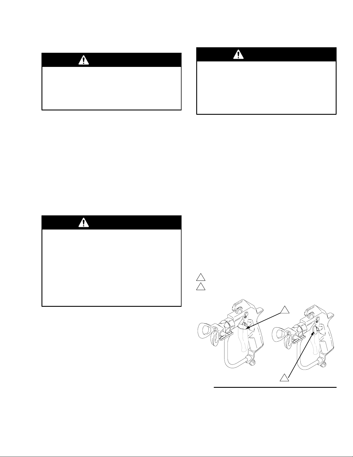
How to Use the Gun Trigger Safety
1. To lock the gun trigger safety, turn the safety to a
right angle with the gun body. See Fig. 1.
2. To unlock the gun trigger safety, push the safety
out and turn it parallel with the gun body.
See Fig. 1.
If you suspect that the spray tip or hose is completely
clogged or that pressure has not been fully relieved,
very slowly loosen the tip guard retaining nut or hose
end coupling and relieve pressure gradually. Clean the
tip or hose obstruction.
Gun trigger safety shown locked
1
Gun trigger safety shown unlocked
2
1
2
Fig. 1
03966
308491 5
Page 6

Installation/Operation
How to Operate the Gun
WARNING
To reduce the risk of component rupture, and serious injury, including fluid injection, do not exceed
the gun’s 4000 psi (276 bar, 27.6 MPa) Maximum
Working Pressure or the maximum working pressure of lowest rated component in the system.
8
30
6. If adjusting the pressure does not give a good
spray pattern, relieve pressure and then try
another tip size.
7. Use a full-open, full-close trigger action. Hold the
gun about 14 in. (350 mm) from and at right angles
to the work surface. Don’t swing the gun in an arc.
Practice to find the best length and speed of
stroke.
How to Adjust the Spray Pattern
1. To adjust the spray pattern direction, relieve pressure. Loosen the tip guard retaining nut (B). Turn
the tip guard/tip groove horizontally (C) for a horizontal pattern and vertically (A) for a vertical
pattern. Tighten the nut. See Fig. 3.
2. The spray tip orifice and spray angle determines
the coverage and size of pattern. When more
A
coverage is needed, use a larger spray tip rather
than increasing fluid pressure.
Fig. 2
1. Connect an electrically conductive fluid hose (A) to
the gun inlet. See Fig. 2.
2. With no tip installed, start the pump. Flush the
pump according to the instructions supplied with it.
Use the lowest pressure possible. Prime the
system with the material.
3. Relieve pressure.
4. Install the SwitchTip (8) and tip guard (30). Follow
the i nstructions in the manual, supplied.
See Fig. 2.
5. Start the pump. Trigger the gun onto test paper.
Adjust the fluid pressure until the spray is
completely atomized. Use the lowest pressure
necessary to get the desired results. Higher pressure may not improve the spray pattern and will
cause premature tip and pump wear.
04731
CAUTION
Openings in the tip guard reduce paint buildup on
the guard while spraying. Damage to the sharp
edges of the openings causes paint to collect at
that area. Never hang the gun by the tip guard.
B
A
C
03968
Fig. 3
3084916
Page 7

Installation/Operation
Care of the Spray Tip and Tip Guard
WARNING
To reduce the risk of fluid injection or splashing in
the eyes or on the skin, do not hold a hand, body
or rag in front of the spray tip when cleaning or
checking a clogged tip. Point the gun toward the
ground or into a waste container when checking to
see if the spray tip is cleared.
Do not try to “blow back” paint; this is not an air
spray gun.
Do not wipe fluid buildup off the gun or spray tip
until pressure is relieved.
Cleaning during the day
If the spray tip clogs while spraying
1. Stop spraying immediately.
2. Lock the gun trigger safety. Rotate the RAC IV tip
handle back 180
3. Unlock the gun trigger safety. Trigger the gun into
a pail or onto the ground to remove the clog.
4. Lock the gun trigger safety. Rotate the tip handle
to the spraying position. See Fig. 4.
5. If the tip is still clogged, engage the gun trigger
safety, shut off the sprayer and disconnect the
power source, and open the pressure drain valve
to relieve pressure. Clean the spray tip as shown
in manual 308644, supplied with the RAC IV.
_. See Fig. 4.
CAUTION
Never soak the entire gun in solvent. Prolonged
exposure to solvent can ruin the packings.
WARNING
SKIN INJECTION HAZARD
To reduce the risk of serious injury,
whenever you are instructed to relieve
pressure, follow the Pressure Relief
Procedure on page 5.
1. Relieve pressure.
2. Clean the front of the tip frequently during the day
to help reduce buildup. Also clean the tip and tip
guard at the end of each work day. Use a solventsoaked brush to clean the spray tip.
Spraying position shown.
1
Turn handle 180_ and
trigger gun to clear clog.
Fig. 4
1
03965
308491 7
Page 8

Installation/Operation
How to Flush the Gun
WARNING
To reduce the risk of serious injury, including
splashing fluid in the eyes or on the skin, or static
electric discharge when flushing:
D Be sure the entire system, including flushing
pails, are properly grounded.
D Remove the tip guard and spray tip.
D Maintain metal to metal contact between the
gun and the flushing pail.
D Use the lowest possible pressure.
04735
Always flush the pump and gun before the fluid being
sprayed can dry in it.
NOTE: This procedure requires a grounded pail of
compatible solvent.
1. Relieve pressure.
2. Remove the tip guard and spray tip. Soak and
clean the parts.
3. Remove the pump intake from the original pail.
4. Put the pump intake in a grounded pail of compatible solvent.
5. Start the pump at its lowest pressure.
6. Trigger the gun into the original pail. When solvent
appears, release the trigger.
7. Now trigger the gun into the solvent pail. Circulate
the fluid until the system is thoroughly flushed.
8. Relieve pressure.
3084918
Page 9

Installation/Operation
How to Check the Gun Diffuser Operation
The Standard Needle and Seat Kit, 237398, has the
number 090 stamped on the needle and seat. The seat
does have a diffuser.
The optional Non-diffused Needle and Seat Kit,
237260, has the number 125 stamped on the needle
and seat. The seat does not have a diffuser.
WARNING
The diffuser, located in the valve seat, creates an
irregular spray pattern when the gun is sprayed
without a tip guard, such as during cleaning. This
reduces the risk of an injection injury.
If you are using the optional Kit 237260, you must
take extra precautions to keep your hands and
body away from the nozzle of the gun.
WARNING
SKIN INJECTION HAZARD
To reduce the risk of serious injury,
whenever you are instructed to relieve
pressure, follow the Pressure Relief
Procedure on page 5.
1. Relieve pressure.
2. Remove the tip guard and spray tip.
3. Start the sprayer and adjust it to the lowest
pressure.
4. Aim the gun into a grounded metal pail while hold-
ing it firmly to the pail. Trigger the gun. If the fluid
emitted is not diffused into an irregular stream,
replace the entire needle kit immediately. See Fig.
5.
Irregular spray pattern
1
Always have the tip guard in place during regular
spraying operations.
Check the diffuser operation weekly. The gun diffuser/
seat (2a) breaks up spray and reduces the risk of fluid
injection when the tip is not installed. Perform the test
below. If it fails, replace the entire Needle and Seat Kit.
Diffuser/seats and needles are not sold separately;
using old parts with new ones will result in leakage.
Fig. 5
2a
1
04735
308491 9
Page 10

Service
2
WARNING
To reduce the risk of serious injury from fluid injection or splashing, always follow the Pressure
Relief Procedure on page 5 before servicing the
gun.
2b
2a
Repair Notes
The needle and seat are available only as a kit which
includes items 2a to 2e.
The Standard Needle and Seat Kit, 237398, has the
number 090 stamped on the needle and seat.
A Non-diffused Needle and Seat Kit, 237260, has the
number 125 stamped on the needle and seat. It is recommended only for use with mastics, sealers and
other high viscosity materials which have fillers that
cannot pass through the standard seat’s diffuser.
Use high quality , general purpose grease where
grease is indicated.
Disassembly
NOTE: If replacing only the needle and seat, Step 4
and 5 are not required. However, removing them
allows you to clean the gun more thoroughly.
1. Relieve pressure.
21
Fig. 7
3. Unscrew the valve seat (2a). Remove the gasket
(2b). See Fig. 7.
28
18
25
Fig. 8
4. Remove one e-clip (27). Push out the pin (18).
Remove the screw (29), pivot pin (28), and trigger
(25). See Fig. 8.
03969
29
27
0473
30
Fig. 6
2. Disconnect the fluid hose (A). Remove the tip
guard (30). Unscrew the spring screw (21) about
1/4 in. (7 mm) to release spring tension.
See Fig. 6.
30849110
A
04731
Fig. 9
5. Remove the screws (24). See Fig. 9.
24
04733
Page 11

Service
1
22
15
Fig. 10
04736
6. Loosen the setscrew (15). Pull the fluid housing (22)
away from the gun body (1). See Fig. 10.
2c
2d
2e
Fig. 12
03974
8. Remove the needle (2c). Unscrew the seal retainer
(2d). Remove the seal (2e). See Fig. 12.
Cleaning
Clean all parts and cavities thoroughly with a compatible solvent. Dry with a rag or compressed air. Replace
any parts that are worn or damage.
Reassembly
1
Torque to 30--40 in-lb (3.4--4.5 N.m)
2
Lips of seal must face into housing
3
Grease inner cavity of housing
16
17
Fig. 11
04734
7. While supporting the spring guide (16) to prevent
bending the needle, loosen the setscrews (17).
Remove the spring guide (16). See Fig. 11.
1
2d
2
2e
3
22
Fig. 13
03975
1. Lightly grease the inner cavities of the fluid housing (22). Install the small seal (2e) so the lips face
into the fluid housing cavity. Install the seal retainer
(2d) and torque to 30--40 in-lb (3.4--4.5 N.m). See
Fig. 13.
308491 11
Page 12

Service
2c
22
Fig. 14
03676
2. Lightly grease the small end of the needle (2c) and
then guide it into the large end of the fluid housing
(22).
Grease the threads
1
Torque to
2
20--25 ft--lb
(27--34 N.m)
2a
2b
22
Grease this side
1
19
20
1
1
Fig. 17
03979
5. If the spring (19) was removed, grease the spring
adjuster (20) and place the spring. Drop this assembly into the gun body (1). See Fig. 17.
Torque to 30--40 in--lb
1
(3.4--4.5 N.m)
Fill cavity with petroleum
2
jelly
1
22
Fig. 15
3. Place the gasket (2b) on the valve seat (2a).
Grease the threads of the valve seat (2a). Screw
the valve seat into the fluid housing (22). Torque to
20--25 ft--lb (27--34 N.m). See Fig. 15.
1
Seat against needle stem
Apply light strength LoctiteR;
2
Torque alternately and evenly to
2 5 -- 3 0 i n -- l b ( 2 . 8 -- 3 . 4 N . m )
Fill cavity with
3
petroleum jelly
16
17
Fig. 16
03977
2
15
Fig. 18
04736
6. Push the fluid housing (22) onto the gun body (1)
until fully seated. Tighten the setscrew (15) to
30--40 in--lb (3.4--4.5 N.m). Fill the setscrew cavity
with petroleum jelly. See Fig. 18.
3
1
3
2
04729
4. Install the spring guide (16) and seat it against the
needle. Loosely thread both setscrews (17) into
the spring guide, then alternately and evenly tighten
the setscrews to 10--15 in-lb (1.1--1.6 N.m). Fill
the setscrew cavities with petroleum jelly.
30849112
Fig. 19
7. Install the screws (24). See Fig. 19.
24
04733
Page 13

Service
2
28
18
25
Fig. 20
8. Position the trigger (25) on the gun body. Insert the
pivot pin (28) into the top hole (A) and secure with
the screw (29) on the other side. Place an e-clip
(27) on one end of the trigger pin (18). Slide the
pin through lower trigger holes and through the slot
(B) in the spring guide (16) (turn the spring guide
to align, as needed). Install the other e-clip (27).
See Fig. 20.
A
B,16
29
27
0473
Test the Gun Before Regular Use
1. Lock the gun trigger safety. Connect a hose to the
gun. Start and prime the pump.
2. Release the gun trigger safety. Trigger the gun into
a waste container. Release the trigger to be sure
the gun immediately stops spraying and that there
arenoleaks.
3. If the gun has a diffuser, check the diffuser using
the procedure on page 9.
4. Install the tip guard (30) before regular use.
See Fig. 22.
Turn in until screw
1
stops
Fig. 21
21
1
03980
9. If it was removed, install the spring tension screw
(21) at the rear of the gun. Then, turn the screw in
until it stops. See Fig. 21.
Fig. 22
30
03965
308491 13
Page 14

Part No. 241705, Series B
Texture Airless Spray Gun
27
Parts
28
21
15
20
19
16
18
2d
2e
22
2c
2b
2a
30
8
Ref.
No. Part No. Description Qty.
1 237680 TEXTURE GUN BODY 1
2 237260 NEEDLE AND SEAT KIT
(parts not sold separately) 1
2a VALVE SEAT 1
2b GASKET 1
2c NEEDLE 1
2d SEAL RETAINER 1
2e SEAL 1
8 L TX531
HDA531 Switch Tip, size 531 (Model 289605) 1
15 102207 SETSCREW
16 189960 SPRING GUIDE 1
17 1 12729 SETSCREW,
18 189958 TRIGGER PIN 1
19 102924 SPRING 1
SwitchTip, size 531 (Model 241705) 1
,1/4--20 1
soc hd 2
29
1
17
36
24
Ref.
No. Part No. Description Qty.
20 189990 SPRING ADJUSTER 1
21 1 10637 ADJUSTING SCREW 1
22 237694 FLUID HOUSING 1
24 1 12774 SCREW,
25 189974 GUN TRIGGER 1
27 1 12410 E-CLIP 2
28 187965 PIVOT PIN 1
29 203953 SCREW,
30 246215 KIT, TIP GUARD 1
34Y 187346 WARNING SHEET
35Y 222385 WARNING CARD
36 1 10755 WASHER, flat 2
Y Replacement Danger and Warning labels, tags and
cards are available at no cost.
27
25
04730
1/4-- 20 2
hex washer hd, 10--24 1
not shown 1
not shown 1
30849114
Page 15

Technical Data
Dimensions
Fluid orifice size 0.125 in. (3.2 mm).................
Inlet size 1/4 npt (m).............................
Fluid tube inside diameter 0.245 in. (6.2 mm)........
Sound Data:
Sound Pressure Level 84 dB(A)*.................
Sound Power Level 93 dB(A)*...................
*Measured while spraying waterbase paint through a
.031 tip at 3,000 psi (207 bar, 20.7 MPa).
Per ISO 3744.
Wetted parts Tungsten carbide,....................
17--4PH passivated stainless steel,
polypropylene, polyethylene
R
Loctite
ration.
is a registered trademark of the Loctite Corpo-
Maximum working pressure 27.6 MPa..............
(276 bar, 4000 psi)
Weight
Length 8.25 in. (210 mm).........................
Height 8.0 in. (203 mm)..........................
includes tip and tip guard 25.7 oz (720 g)..........
Graco Phone Number
TO PLACE AN ORDER, contact your Graco distributor, or call this number to identify the distributor
closest to you: 1--800--690--2894 Toll Free.
308491 15
Page 16

The Graco Warranty and Disclaimers
Graco warrants all equipment referenced in this document which is manufactured by Graco and bearing its name to be free from
defects in materialand workmanship on the date of sale to the original purchaser for use. With the exception of any special, extended,
or limited warranty published by Graco, Graco will, for a period of twelve months from the date of sale, repair or replace any part of the
equipmentdetermined by Graco to be defective. Thiswarranty applies only when the equipment is installed,operated and maintained
in accordance with Graco’s written recommendations.
This warranty does not cover, and Graco shall not be liable for general wear and tear, or any malfunction,damage or wear caused by
faultyinstallation,misapplication, abrasion,corrosion, inadequate or improper maintenance,negligence, accident, tampering,orsubstitution of non-Graco component parts. Nor shall Graco be liable for malfunction, damage or wear caused by the incompatibility of
Graco equipment with structures, accessories, equipment or materials not supplied by Graco, or the improper design, manufacture,
installation, operation or maintenance of structures, accessories, equipment or materials not supplied by Graco.
This warranty is conditioned upon the prepaid return of the equipment claimed to be defective to an authorized Graco distributor for
verification of the claimed defect. If the claimed defect is verified, Graco will repair or replace free of charge any defective parts. The
equipmentwill be returnedtotheoriginal purchaser transportation prepaid. If inspectionoftheequipment does notdiscloseany defect
in material or workmanship, repairs will be made at a reasonable charge, which charges may include the costs of parts, labor, and
transportation.
THIS WARRANTY IS EXCLUSIVE, AND IS IN LIEU OF ANY OTHER WARRANTIES, EXPRESS OR IMPLIED, INCLUDING BUT
NOT LIMITED TO WARRANTY OF MERCHANTABILITY OR WARRANTY OF F ITNESS FOR A PARTICULAR PURPOSE.
Graco’ssoleobligation and buyer’s sole remedy forany breachof warrantyshallbeas set forth above. The buyer agrees that no other
remedy (including,but not limited to, incidentalor consequentialdamages for lost profits, lost sales, injury to person or property, or any
other incidentalor consequential loss) shall be available. Any action for breach of warranty must be brought within two (2)years of the
date of sale.
GRACO MAKES NO WARRANTY, AND DISCLAIMS ALL IMPLIED WARRANTIES OF MERCHANTABILITY AND FITNESS FOR
A PARTICULAR PURPOSE, IN CONNECTION WITH ACCESSORIES, EQUIPMENT, MATERIALS OR COMPONENTS SOLD
BUT NOT MANUFACTURED BY GRACO. These items sold, but not manufactured by Graco (such as electric motors, switches,
hose, etc.), are subject to the warranty, if any, of their manufacturer. Graco will provide purchaser with reasonable assistance in making any claim for breach of these warranties.
In no event will Graco be liable for indirect, incidental, special or consequential damages resulting from Graco supplying equipment
hereunder, or the furnishing, performance, or use of any products or other goods sold hereto, whether due to a breach of contract,
breach of warranty, the negligence of Graco, or otherwise.
FOR GRACO CANADA CUST
The parties acknowledge that they have required that the present document, as well as all documents, notices and legal proceedings
entered into, given or instituted pursuant hereto or relating directly or indirectly hereto, be drawn up in English. Les parties reconnaissent avoir convenu que la rédaction du présente document sera en Anglais, ainsi que tous documents, avis et procédures judiciaires
exécutés, donnés ou intentés à la suite de ou en rapport, directement ou indirectement, avec les procedures concernées.
OMERS
ADDITIONAL WARRANTY COVERAGE
Graco does provide extended warranty and wear warranty for products described in the “Graco Contractor Equipment Warranty
Program”.
All written and visual data contained in this document reflects the latest product information available at the time of publication.
Graco reserves the right to make changes at any time without notice.
This manual contains English. MM 308491
International Offices: Belgium, China, Japan, Korea
Graco Headquarters: Minneapolis
1/1995, Revised 10/2008
30849116
 Loading...