

Page 1
Instructions - Parts
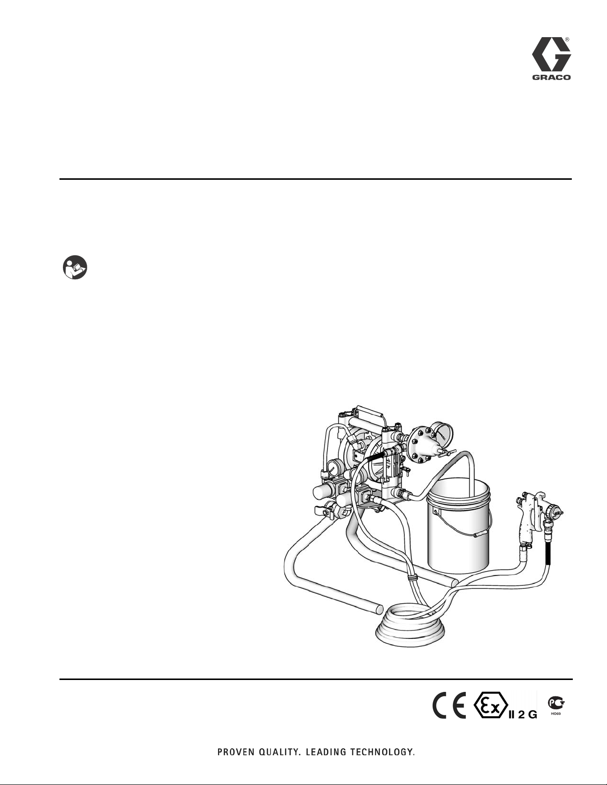
Finex Airspray
312473B
Package Sprayer
Package solutions for pumping and spraying finishing materials. For professional use
only.
Important Safety Instructions
Read all warnings and instructions in this manual and in
your respective pump manual. Save these instructions.
Models:
289353 with Finex Airspray Gun
100 psi (7 bar, 0.7 MPa) Maximum Working Pressure
ENG
289354 with Finex HVLP Gun
100 psi (7 bar, 0.7 MPa) Maximum Working Pressure
TI10823A
Page 2

Related Manuals
Contents
Related Manuals . . . . . . . . . . . . . . . . . . . . . . . . . . . 2
Warnings . . . . . . . . . . . . . . . . . . . . . . . . . . . . . . . . . 3
Installation . . . . . . . . . . . . . . . . . . . . . . . . . . . . . . . . 5
Grounding . . . . . . . . . . . . . . . . . . . . . . . . . . . . . . 5
Flush Before Using Equipment . . . . . . . . . . . . . . 5
Components . . . . . . . . . . . . . . . . . . . . . . . . . . . . . . . 6
Sprayer Components . . . . . . . . . . . . . . . . . . . . . 6
Required Components (not included) . . . . . . . . . 6
Recommended Components . . . . . . . . . . . . . . . 6
Pump Operation and Repair . . . . . . . . . . . . . . . . . . 6
Pressure Relief . . . . . . . . . . . . . . . . . . . . . . . . . . . . 6
Typical Installation . . . . . . . . . . . . . . . . . . . . . . . . . 7
Setup/Installation . . . . . . . . . . . . . . . . . . . . . . . . . . . 8
Grounding . . . . . . . . . . . . . . . . . . . . . . . . . . . . . . . . 9
Related Manuals
Manual Description
308553
312388
308325 Fluid Pressure Regulators
Husky
Finex
™
307 Air-Operated Diaphragm Pumps
™
Gun
Flush . . . . . . . . . . . . . . . . . . . . . . . . . . . . . . . . . . . . . 9
Prime . . . . . . . . . . . . . . . . . . . . . . . . . . . . . . . . . . . . 10
Spraying . . . . . . . . . . . . . . . . . . . . . . . . . . . . . . . . . 11
Shutdown . . . . . . . . . . . . . . . . . . . . . . . . . . . . . . . . 11
Maintenance . . . . . . . . . . . . . . . . . . . . . . . . . . . . . . 12
Troubleshooting . . . . . . . . . . . . . . . . . . . . . . . . . . . 13
Parts . . . . . . . . . . . . . . . . . . . . . . . . . . . . . . . . . . . . 14
Finex Sprayer Package . . . . . . . . . . . . . . . . . . . 14
Dimensions . . . . . . . . . . . . . . . . . . . . . . . . . . . . . . . 15
Technical Data . . . . . . . . . . . . . . . . . . . . . . . . . . . . 15
Graco Standard Warranty . . . . . . . . . . . . . . . . . . . 16
Graco Information . . . . . . . . . . . . . . . . . . . . . . . . . 16
2 312473B
Page 3
Warnings
Warnings
The following warnings are for the setup, use, grounding, maintenance, and repair of this equipment. The exclamation point symbol alerts you to a general warning and the hazard symbol refers to procedure-specific risk. Refer back
to these warnings. Additional, product-specific warnings may be found throughout the body of this manual where
applicable.
WARNING
FIRE AND EXPLOSION HAZARD
Flammable fumes, such as solvent and paint fumes, in work area can ignite or explode. To help prevent
fire and explosion:
• Use equipment only in well ventilated area.
• Eliminate all ignition sources; such as pilot lights, cigarettes, portable electric lamps, and plastic drop
cloths (potential static arc).
• Keep work area free of debris, including solvent, rags and gasoline.
• Do not plug or unplug power cords, or turn power or light switches on or off when flammable fumes
are present.
• Ground all equipment in the work area. See Grounding instructions.
• Use only grounded hoses.
• Hold gun firmly to side of grounded pail when triggering into pail.
• If there is static sparking or you feel a shock, stop operation immediately. Do not use equipment
until you identify and correct the problem.
• Keep a working fire extinguisher in the work area.
EQUIPMENT MISUSE HAZARD
Misuse can cause death or serious injury.
• Do not operate the unit when fatigued or under the influence of drugs or alcohol.
• Do not exceed the maximum working pressure or temperature rating of the lowest rated system
component. See Technical Data in all equipment manuals.
• Use fluids and solvents that are compatible with equipment wetted parts. See Technical Data in all
equipment manuals. Read fluid and solvent manufacturer’s warnings. For complete information
about your material, request MSDS forms from distributor or retailer.
• Check equipment daily. Repair or replace worn or damaged parts immediately with genuine manufacturer’s replacement parts only.
• Do not alter or modify equipment.
• Use equipment only for its intended purpose. Call your distributor for information.
• Route hoses and cables away from traffic areas, sharp edges, moving parts, and hot surfaces.
• Do not kink or over bend hoses or use hoses to pull equipment.
• Keep children and animals away from work area.
• Comply with all applicable safety regulations.
PRESSURIZED EQUIPMENT HAZARD
Fluid from the gun/dispense valve, leaks, or ruptured components can splash in the eyes or on skin and
cause serious injury.
• Follow Pressure Relief Procedure in this manual, when you stop spraying and before cleaning,
checking, or servicing equipment.
• Tighten all fluid connections before operating the equipment.
• Check hoses, tubes, and couplings daily. Replace worn or damaged parts immediately.
312473B 3
Page 4
Warnings
WARNING
TOXIC FLUID OR FUMES HAZARD
Toxic fluids or fumes can cause serious injury or death if splashed in the eyes or on skin, inhaled, or
swallowed.
• Read MSDS’s to know the specific hazards of the fluids you are using.
• Store hazardous fluid in approved containers, and dispose of it according to applicable guidelines.
• Always wear impervious gloves when spraying or cleaning equipment.
PERSONAL PROTECTIVE EQUIPMENT
You must wear appropriate protective equipment when operating, servicing, or when in the operating
area of the equipment to help protect you from serious injury, including eye injury, inhalation of toxic
fumes, burns, and hearing loss. This equipment includes but is not limited to:
• Protective eyewear
• Clothing and respirator as recommended by the fluid and solvent manufacturer
•Gloves
• Hearing protection
PRESSURIZED ALUMINUM PARTS HAZARD
Do not use 1,1,1-trichloroethane, methylene chloride, other halogenated hydrocarbon solvents or fluids
containing such solvents in pressurized aluminum equipment. Such use can cause serious chemical
reaction and equipment rupture, and result in death, serious injury, and property damage.
4 312473B
Page 5
Installation
Installation
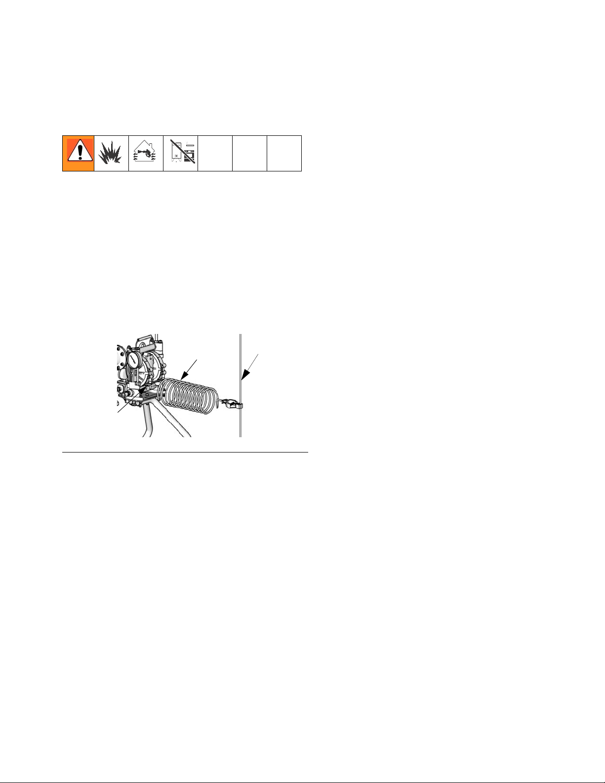
Grounding
The equipment must be grounded. Grounding reduces
the risk of static and electric shock by providing an
escape wire for the electrical current due to static build
up or in the event of a short circuit.
Pump: use the ground wire and clamp (supplied). See
F
IG. 1. Use the ground screw (GS) and lock washer
(LW) to attach the ground wire (N) at the rear of the air
motor. Tighten the screw securely. Connect the other
end of the ground wire to a true earth ground (P).
N
P
To maintain grounding continuity when flushing or
relieving pressure: hold metal part of the spray
gun/dispense valve firmly to the side of a grounded
metal pail, then trigger the gun/valve.
Flush Before Using Equipment
The equipment was tested with water. To avoid contaminating your fluid with water, flush the equipment with a
compatible solvent before using the equipment. See
your pump manual. See Related Manuals, page 2.
GS, LW
FIG. 1. Ground Wire
Air and fluid hoses: use only electrically conductive
hoses.
Air compressor: follow manufacturer’s recommendations.
Spray gun / Dispense valve: ground through connec-
tion to a properly grounded air or fluid hose and pump.
Air hose is conductive and used to ground gun. If adding
lengths to hose be sure to use conductive hoses.
Fluid supply container: follow local code.
Object being sprayed: follow local code.
Solvent pails used when flushing: follow local code.
Use only conductive metal pails, placed on a grounded
surface. Do not place the pail on a nonconductive surface, such as paper or cardboard, which interrupts
grounding continuity.
TI10824A
312473B 5
Page 6

Controls and Components
Controls and Components
Trapped air can cause the pump to cycle unexpectedly,
which could result in serious injury from splashing or
moving parts.
Sprayer Controls
• Pump air pressure regulator (C): a locking regula-
tor to adjust air pressure to the motor and fluid outlet
pressure of pump. View the air pressure gauge to
read air pressure.
• Gun air pressure regulator (D): a locking regulator
to adjust air pressure to the gun. View the air pressure gauge to read air pressure.
• Fluid pressure regulator (E): used to adjust the
fluid pressure to the spray gun.
• Bleed-type master air valve (L): required in your
system to relieve air trapped between it and the air
motor when the valve is closed.
Pump Operation and Repair
Follow the Pressure Relief Procedure in your pump
manual before cleaning or repairing your equipment.
For complete instructions and warnings see your respective pump manual. See
Related Manuals
, page 2.
Required Components
• Main Air Supply (J): connects air supply from air
compressor to pump.
(not included)
Recommended Components
• Air line filter (F): removes harmful contaminants
from entering the air control module and air motor.
• Air line moisture drain valve (M): installed at the
bottom of each air line drop, to drain moisture.
6 312473B
Page 7

Typical Installation
B
Typical Installation
True Earth Ground
M
E
I
A
F
J
C
F
H
K
D
L
G
TI10825A
FIG. 2: Typical Installation (Finex Airspray Gun Shown)
Key:
APump
B Bleed-type Master Air Line Shutoff Valve
C Pump Air Pressure Regulator
D Gun Air Pressure Regulator
E Gun Fluid Pressure Regulator
FAir Filter
312473B 7
GHose Set
H Suction Hose
I Pump Ground Wire (required)
J Main Air Supply Line
K Spray Gun, Finex Airspray or HVLP
L Bleed Type Master Air Valve
M Air Line Moisture Drain
Page 8

Pressure Relief
Pressure Relief
Follow pressure relief procedure when you stop spraying and before cleaning, checking, or servicing the
equipment.
1. Shut off the bleed-type air valve.
TI10826A
-
2. Hold the gun firmly against a grounded metal pail
and trigger the gun.
TI10828A
3. Connect the gun fluid hose to fluid regulator. Tighten
securely.
TI10829A
4. Connect the fluid hose to the gun. Tighten securely.
TI10831A
5. Ground the pump. See Grounding, page 9.
TI10824A
Setup/Installation
Before using the equipment for the first time, follow this
procedure.
1. Connect the air hose to the gun air regulator.
TI10829A
2. Connect the air hose to the gun.
TI10830A
6. Connect the main air supply to the bleed-type air
valve.
TI10829A
7. Flush. See Flush, page 9.
FLUSH WASTE
TI10835A
TI10828A
8. Prime. See Prime, page 10.
PAINT
TI10832A
WASTE
TI10828A
9. Spray. See Spraying, page 11.
TI10833A
8 312473B
Page 9

Grounding
Grounding
Read Fire and Explosion Hazard. See page 3.
1. Connect the ground wire clamp to a true earth
ground.
TI10824A
2. Ground the object being sprayed, fluid supply container, and all other equipment in the spray area.
TI10832A
4. Turn off both air regulators.
-
-
TI10836A
5. Open the bleed-type air valve.
+
TI10827A
6. Open the pump air regulator until the pump starts.
+
TI10836A
7. When clean solvent flows without air from the gun
stop spraying.
3. Ground all solvent pails. Use only metal pails. Do
not place on a non-conductive surface such as
paper or cardboard.
TI10835A
Flush
1. Relieve pressure. See Typical Installation, page 7.
2. Remove the air cap. Clean separately.
TI10834A
3. Place the suction tube in solvent.
TI10870A
8. Remove the suction tube from the solvent. Continue
to spray until all solvent is out of the gun.
TI10835A
TI10870A
9. Close the bleed type air valve.
TI10826A
-
10. Relieve pressure. See Typical Installation, page 7.
TI10835A
312473B 9
Page 10

Prime
Prime
1. Shut off both air regulators and the bleed-type air
valve.
-
2. Shut off the fluid regulator.
3. Install the air cap.
-
TI10836A
TI10826A
-
-
TI10837A
7. Adjust the fluid pressure regulator.
+
TI10837A
8. Hold the gun firmly against a grounded metal pail
and trigger the gun until fluid flow is steady. Release
the trigger. The equipment is ready to spray.
TI10828A
TI10834A
4. Place the suction tube in the fluid.
TI10832A
5. Open the bleed-type air valve.
+
TI10827A
6. Open the pump air regulator until the pump starts.
+
TI10836A
10 312473B
Page 11

Spraying
Spraying
1. Adjust fluid flow using the pump air regulator or the
fluid pressure regulator.
+
TI10836A
2. Adjust fluid pressure so stream from gun travels 6–8
in. straight before falling off.
6 in. to 8 in.
(152 mm to 203 mm)
3. Adjust the gun air regulator to achieve proper spray
gun atomization.
+
TI10837A
TI10838A
Shutdown
1. Flush. See Flush page 9.
2. Relieve pressure. See Typical Installation, page 7.
TI10836A
4. Test the spray pattern. Read the fluid manufacturer’s
recommendations. Adjust as necessary.
+
TI10839A
TI10833A
312473B 11
Page 12

Maintenance
Maintenance
Relieve pressure before servicing. See Typical
Installation, page 7.
1. Flush. See Flush, page 9.
2. Clean the air cap and fluid nozzle.
TI10834A
3. Clean the suction tube and inlet strainer, using a
compatible solvent.
TI10840A
6. Clean the accessory air filter (not supplied) in your
main air line.
TI10871A
TI10842A
TI10841A
4. Clean the outside of the sprayer, using a soft cloth
and compatible solvent.
TI10823A
5. Check the hoses, tubes, and couplings every day.
Tighten all fluid connections before each use.
TI10830A
12 312473B
TI10829A
Page 13

Troubleshooting
Troubleshooting
Relieve pressure before servicing. See Typical
Installation, page 8.
Problem Cause Solution
Pump will not run, or stops. Air line valve shut off. Open valve.
Clogged fluid line or spray gun. Clear, service. Do not allow fluid to
setup in the pump and lines.
Stuck or damaged pump air valve. Service pump. Use filtered air.
Pump runs erratically. Clogged suction line or inlet strainer. Clear.
Pump runs too fast. Exhausted fluid supply. Refill fluid supply and prime sprayer.
Pump cycles at stall or fails to hold
pressure at stall.
Audible air leak. Worn air valve. Service pump.
Air bubbles in fluid. Loose suction line. Tighten. Use a compatible liquid
Poor finish or irregular pattern. Incorrect fluid or air pressure at gun. See gun manual; read fluid manufac-
Worn check valves or o-rings. Service pump.
thread sealant or PTFE tape on connections.
Ruptured diaphragm. Service pump.
turer’s recommendations. Use fluid
regulator.
Fluid is too thick or too thin. Thin or thicken fluid; read fluid manu-
facturer’s recommendations.
Dirty, worn, or damaged spray gun. Service gun.
Fluid is settling out. Order Part No. 245081 Agitator Kit.
312473B 13
Page 14

Parts
Parts
289353 with Finex Airspray Gun 289354 with Finex HVLP Gun
18
10
25
21
11
2
9
8
1
24
7
3
12
23
16
15
6
19
17
22a, 22b
13
5
Ref. Part Description Qty.
1 289609 PLATE, mounting 1
2 D31331 PUMP, diaphragm 1
3 164856 FITTING, nipple, reducing 2
4 15D921 LEG, right, (finished) 1
5 15D922 LEG, left, (finished) 1
6 241976 REGULATOR, press, fluid 1
7 162453 FITTING, 1/4 NPSM X 1/4 NPT 1
8 116513 REGULATOR, air 2
9 110436 GAUGE, pressure air 2
10 115219 FITTING, tee, 1/4 NPT 1
11 289610 HANDLE, wire pump 1
12 15R472 FASTENER, hex HD, flanged 1/4-2 4
13 114104 SCREW, mach, hex wash HD 4
15 289608 STRAINER, suction line 1
16 111864 CONNECTOR, male 2
14 312473B
Ref. Part Description Qty.
17 590570 HOSE, polyethylene 4ft
18 116473 VALVE, vented 2 way 1
19 237686 WIRE, ground assembly w/clamp 1
20 289522 HOSE, set, bundled (not shown)
21 608780 FITTING, elbow male 2
22a 289254 GUN, GRACO Finex, conv, press 1
22b 289249 GUN, GRACO Finex HVLP 1
23 115942 NUT, lock hex 8
24 104641 FITTING, bulkhead 1
25 111763 FITTING, elbow 1/4 NPT 1
26 513066 TUBE, 3/8” OD Nylon (not shown) 1ft
4
(289353)
240421 HOSE, set, bundled (not shown)
(289354)
TI10872A
25ft
25ft
Page 15

Dimensions
Dimensions
19.19 in.
(48.74 cm.)
TI10874A
19.26 in.
(48.92 cm.)
Technical Data
Maximum fluid working pressure . . . . . . . . . . . . . 100 psi (0.7 MPa, 7 bar)
Maximum incoming air pressure . . . . . . . . . . . . . 100 psi (0.7 MPa, 7 bar)
Operating temperature range . . . . . . . . . . . . . . . 40 -109 F (4.4 - 43 C)
Package Weight . . . . . . . . . . . . . . . . . . . . . . . . . . 19.8 lbs (9.0 kg)
Wetted Parts
Pump . . . . . . . . . . . . . . . . . . . . . see related manuals, page 2.
Gun. . . . . . . . . . . . . . . . . . . . . . . see related manuals, page 2.
Fluid Regulator. . . . . . . . . . . . . see related manuals, page 2.
Other. . . . . . . . . . . . . . . . . . . . . . nylon, acetal, SST, polyethylene
Sound levels: Refer to related pump and gun manuals. See page 2.
12.02 in.
(30.53 cm.)
TI10873A
312473B 15
Page 16

Graco Standard Warranty
Graco warrants all equipment referenced in this document which is manufactured by Graco and bearing its name to be free from defects in
material and workmanship on the date of sale to the original purchaser for use. With the exception of any special, extended, or limited warranty
published by Graco, Graco will, for a period of twelve months from the date of sale, repair or replace any part of the equipment determined by
Graco to be defective. This warranty applies only when the equipment is installed, operated and maintained in accordance with Graco’s written
recommendations.
This warranty does not cover, and Graco shall not be liable for general wear and tear, or any malfunction, damage or wear caused by faulty
installation, misapplication, abrasion, corrosion, inadequate or improper maintenance, negligence, accident, tampering, or substitution of
non-Graco component parts. Nor shall Graco be liable for malfunction, damage or wear caused by the incompatibility of Graco equipment with
structures, accessories, equipment or materials not supplied by Graco, or the improper design, manufacture, installation, operation or
maintenance of structures, accessories, equipment or materials not supplied by Graco.
This warranty is conditioned upon the prepaid return of the equipment claimed to be defective to an authorized Graco distributor for verification of
the claimed defect. If the claimed defect is verified, Graco will repair or replace free of charge any defective parts. The equipment will be returned
to the original purchaser transportation prepaid. If inspection of the equipment does not disclose any defect in material or workmanship, repairs will
be made at a reasonable charge, which charges may include the costs of parts, labor, and transportation.
THIS WARRANTY IS EXCLUSIVE, AND IS IN LIEU OF ANY OTHER WARRANTIES, EXPRESS OR IMPLIED, INCLUDING BUT NOT LIMITED
TO WARRANTY OF MERCHANTABILITY OR WARRANTY OF FITNESS FOR A PARTICULAR PURPOSE.
Graco’s sole obligation and buyer’s sole remedy for any breach of warranty shall be as set forth above. The buyer agrees that no other remedy
(including, but not limited to, incidental or consequential damages for lost profits, lost sales, injury to person or property, or any other incidental or
consequential loss) shall be available. Any action for breach of warranty must be brought within two (2) years of the date of sale.
GRACO MAKES NO WARRANTY, AND DISCLAIMS ALL IMPLIED WARRANTIES OF MERCHANTABILITY AND FITNESS FOR A
PARTICULAR PURPOSE, IN CONNECTION WITH ACCESSORIES, EQUIPMENT, MATERIALS OR COMPONENTS SOLD BUT NOT
MANUFACTURED BY GRACO. These items sold, but not manufactured by Graco (such as electric motors, switches, hose, etc.), are subject to
the warranty, if any, of their manufacturer. Graco will provide purchaser with reasonable assistance in making any claim for breach of these
warranties.
In no event will Graco be liable for indirect, incidental, special or consequential damages resulting from Graco supplying equipment hereunder, or
the furnishing, performance, or use of any products or other goods sold hereto, whether due to a breach of contract, breach of warranty, the
negligence of Graco, or otherwise.
FOR GRACO CANADA CUSTOMERS
The Parties acknowledge that they have required that the present document, as well as all documents, notices and legal proceedings entered into,
given or instituted pursuant hereto or relating directly or indirectly hereto, be drawn up in English. Les parties reconnaissent avoir convenu que la
rédaction du présente document sera en Anglais, ainsi que tous documents, avis et procédures judiciaires exécutés, donnés ou intentés, à la suite
de ou en rapport, directement ou indirectement, avec les procédures concernées.
Graco Information
For the latest information about Graco products, visit www.graco.com.
TO PLACE AN ORDER, contact your Graco distributor or call to identify the nearest distributor.
Phone: 612-623-6921 or Toll Free: 1-800-328-0211 Fax: 612-378-3505
All written and visual data contained in this document reflects the latest product information available at the time of publication.
Graco reserves the right to make changes at any time without notice.
This manual contains English. MM 312473
Graco Headquarters: Minneapolis
International Offices: Belgium, China, Japan, Korea
GRACO INC. P.O. BOX 1441 MINNEAPOLIS, MN 55440-1441
Copyright 2007, Graco Inc. is registered to ISO 9001
www.graco.com
Revised 08/2009
 Loading...