

Page 1
Instructions-Parts
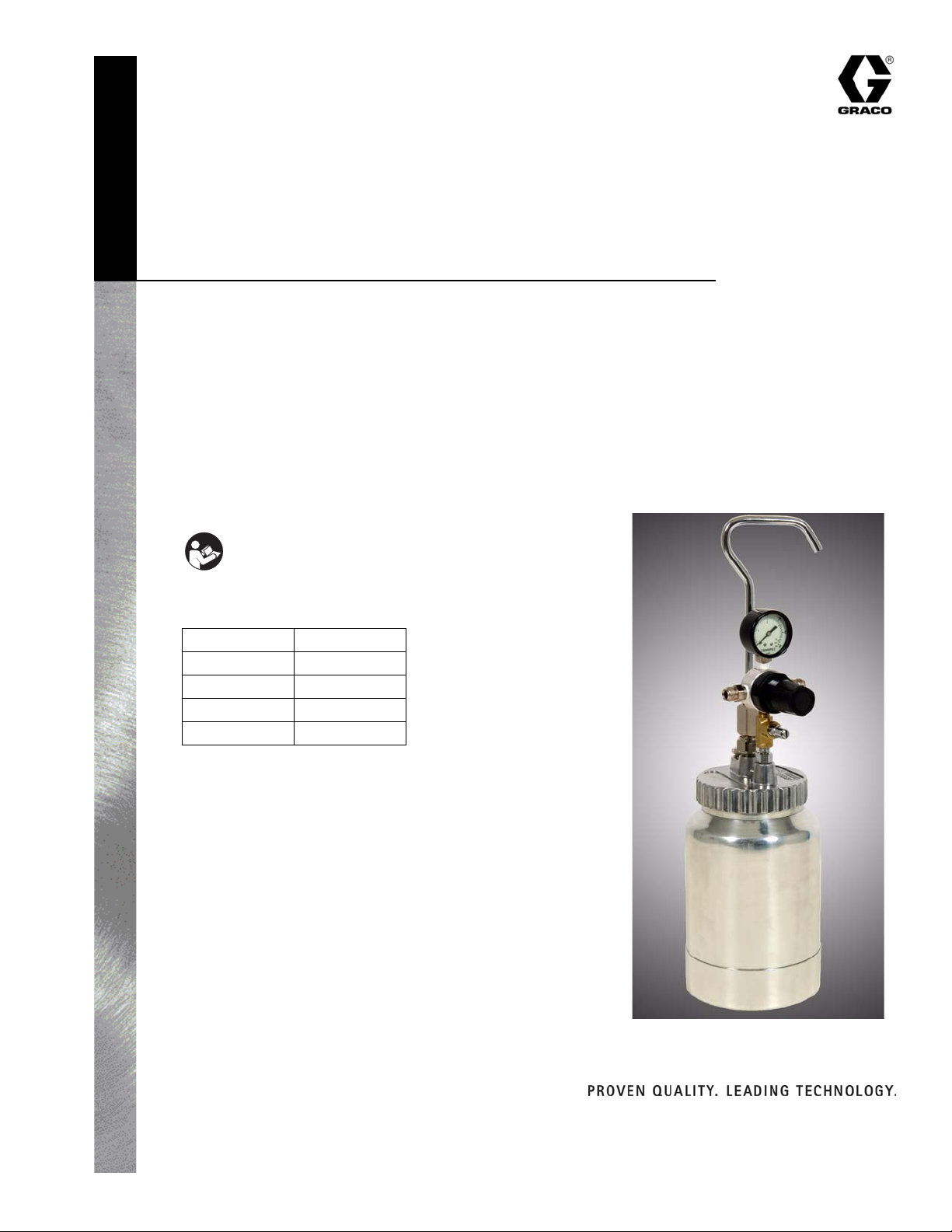
2-Quart (1.9 Liter)
Pressure Cup
312111A
For controlling atomizing air and fluid pressure for any pressure feed manual
spray gun when more than one quart of fluid will be used.
288776
50 psi (0.35 MPa, 3.5 bar) Maximum Regulated Fluid Pressure
50 psi (0.35 MPa, 3.5 bar) Maximum Air Inlet Pressure
Important Safety Instructions
Read all warnings and instructions in this manual.
Save these instructions.
This manual is available in the following languages.
English 312111
Spanish 312112
French 312113
German 312114
Italian 312115
Contents
Warnings . . . . . . . . . . . . . . . . . . . . . . . . . . . . . . .2
Description . . . . . . . . . . . . . . . . . . . . . . . . . . . . .3
Set-Up . . . . . . . . . . . . . . . . . . . . . . . . . . . . . . . . .4
Operation . . . . . . . . . . . . . . . . . . . . . . . . . . . . . .5
Maintenance . . . . . . . . . . . . . . . . . . . . . . . . . . . .6
Troubleshooting . . . . . . . . . . . . . . . . . . . . . . . . . 6
Parts . . . . . . . . . . . . . . . . . . . . . . . . . . . . . . . . . .8
Technical Data . . . . . . . . . . . . . . . . . . . . . . . . . . 9
Graco Standard Warranty . . . . . . . . . . . . . . . . 10
Graco Information . . . . . . . . . . . . . . . . . . . . . .10
Graco Inc. P.O. Box 1441 Minneapolis, MN 55440-1441
Copyright 2007, Graco Inc. is registered to I.S. EN ISO 9001
Page 2
Warnings
Warnings
The following warnings are for the setup, use, grounding, maintenance, and repair of this equipment. The exclamation point symbol alerts you to a general warning and the hazard symbol
refers to procedure-specific risk. Refer back to these warnings. Additional, product-specific
warnings may be found throughout the body of this manual where applicable.
WARNING
FIRE AND EXPLOSION HAZARD
Flammable fumes, such as solvent and paint fumes, in work area can ignite or explode.
To help prevent fire and explosion:
• Use equipment only in well ventilated area.
• Eliminate all ignition sources; such as pilot lights, cigarettes, portable electric
lamps, and plastic drop cloths (potential static arc).
• Keep work area free of debris, including solvent, rags and gasoline.
• Do not plug or unplug power cords or turn lights on or off when flammable fumes
are present.
• Ground all equipment in the work area. See Grounding instructions.
• If there is static sparking or you feel a shock, stop operation immediately. Do not
use equipment until you identify and correct the problem.
• Keep a working fire extinguisher in the work area.
EQUIPMENT MISUSE HAZARD
Misuse can cause death or serious injury.
• Do not operate the unit when fatigued or under the influence of drugs or alcohol.
• Do not exceed the maximum working pressure or temperature rating of the lowest
rated system component. See Technical Data in all equipment manuals.
• Use fluids and solvents that are compatible with equipment wetted parts. See Tech-
nical Data in all equipment manuals. Read fluid and solvent manufacturer’s warnings. For complete information about your material, request MSDS forms from
distributor or retailer.
• Check equipment daily. Repair or replace worn or damaged parts immediately with
genuine manufacturer’s replacement parts only.
• Do not alter or modify equipment.
• Use equipment only for its intended purpose. Call your distributor for information.
• Route hoses and cables away from traffic areas, sharp edges, moving parts, and
hot surfaces.
• Do not kink or over bend hoses or use hoses to pull equipment.
• Keep children and animals away from work area.
• Comply with all applicable safety regulations.
2 312111A
Page 3
Warnings
WARNING
PRESSURIZED EQUIPMENT HAZARD
Fluid from the gun/dispense valve, leaks, or ruptured components can splash in the
eyes or on skin and cause serious injury.
•Follow Pressure Relief Procedure in this manual, when you stop spraying and
before cleaning, checking, or servicing equipment.
• Tighten all fluid connections before operating the equipment.
• Check hoses, tubes, and couplings daily. Replace worn or damaged parts immediately.
TOXIC FLUID OR FUMES HAZARD
Toxic fluids or fumes can cause serious injury or death if splashed in the eyes or on
skin, inhaled, or swallowed.
• Read MSDS’s to know the specific hazards of the fluids you are using.
• Store hazardous fluid in approved containers, and dispose of it according to applicable guidelines.
• Always wear impervious gloves when spraying or cleaning equipment.
PRESSURIZED ALUMINUM PARTS HAZARD
Do not use 1,1,1-trichloroethane, methylene chloride, other halogenated hydrocarbon
solvents or fluids containing such solvents in pressurized aluminum equipment. Such
use can cause serious chemical reaction and equipment rupture, and result in death,
serious injury, and property damage.
PERSONAL PROTECTIVE EQUIPMENT
You must wear appropriate protective equipment when operating, servicing, or when in
the operating area of the equipment to help protect you from serious injury, including
eye injury, inhalation of toxic fumes, burns, and hearing loss. This equipment includes
but is not limited to:
• Protective eyewear
• Clothing and respirator as recommended by the fluid and solvent manufacturer
•Gloves
• Hearing protection
312111A 3
Page 4

Description
The Model 288776 2-quart (1.9-liter) pressure
cup is designed to be used with any pressure
feed manual spray gun when more than 1
quart of fluid will be used. Pressure cups provide a better degree of control over atomizing
air and fluid pressure than siphon feed equipment. The Model 288776 enables you to spray
a wider range of refinish materials and has a
full 2-quart (1.9 liter) capacity when needed.
The regulator assembly controls pressure of
fluid in the cup from 0-50 psi (0.35 MPa, 3.5
bar). The manual pressure relief valve allows
air pressure to bleed from cup.
Set-Up
Description
Never tamper with the automatic pressure
relief valve (6b). The automatic relief valve
limits the maximum air pressure entering the
cup. If the relief valve does not work properly,
over-pressurization may occur and cause the
cup to rupture or explode. Air pressure in the
cup must never exceed 50 psi (0.35 MPa, 3.5
bar).
Always disconnect cup assembly from air supply and relieve pressure in cup (open manual
relief valve counter-clockwise) before installing
or removing canister from lid assembly.
1. Connect air hose to air inlet of gun and to air outlet on cup regulator as shown.
2. Connect fluid hose to fluid inlet of gun and to cup fluid outlet as shown.
3. Connect handle to top of cup as shown.
4. It is best for the air supply line to pass through a Graco Air Control Unit to filter dirt from the air and extract water and oil. Connect the air supply hose to the air inlet fitting on cup regulator.
Note: Follow the manufacturer’s directions for the mixing and preparation of material. Strain material using a fine mesh screen to prevent the entry of foreign matter and the clogging of fluid passageways.
4 312111A
Page 5

Operation
Operation
Always disconnect cup assembly from air supply and relieve pressure in cup (open manual
pressure relief valve counter-clockwise) before
installing or removing canister from lid assembly.
7. To decrease paint flow, pull out regulator
knob and turn counter-clockwise to lower
cup pressure. Open the relief valve to
bleed off excess pressure. Reseal relief
valve. Repeat step 6. The cup lid has a
check valve that prevents the cup from
losing pressure until the relief valve is
opened.
1. Pull out regulator knob and turn fully
counter-clockwise. Open manual pressure relief valve on cup lid (counter-clockwise).
2. Open lid and fill cup with desired sprayable material.
3. Close lid and seal by turning clockwise hand-tight.
4. Close relief valve on cup lid hand-tight turning clockwise.
5. Set wall-mounted regulator (not supplied) to desired air pressure. (This is your atomizing air.)
6. Slowly turn the cup regulator knob clockwise while pulling the gun trigger fully
back. Continue clockwise until desired
flow is achieved. Push in regulator knob to
lock. Maximum cup pressure is 50 psi
(0.35 MPa, 3.5 bar).
8. Atomizing air for the spray gun can be adjusted at the gun by means of an air adjusting valve on the spray gun.
Note: To achieve desired cup pressure you
must always start at a lower pressure and
adjust up to the desired setting.
Cup Pressure
Regulator
Knob
Automatic
Pressure
Relief Valve
Fluid Outlet
Cup Air Outlet
Manual
Pressure
Relief Valve
ti7063
312111A 5
Page 6

Maintenance
Paint can erupt from the cup due to rapid
depressurization. Never open the cup prior to
turning cup pressure regulator knob to the full
“off” position (counter-clockwise) and relieving cup pressure by opening (counter-clockwise) manual pressure relief valve.
1. After relieving cup pressure and turning cup pressure regulator to the full “off” position (counter-clockwise), open cup lid by turning counter-clockwise.
2. Pour out any remaining material and add a compatible solvent.
Maintenance
3. Repeat steps 3, 4, and 6 in Operation on
page 5 and spray until clean solvent
appears. Cup and gun material passages
should be clean now.
4. Depressurize cup (See Operation, step
1) and empty remaining solvent from cup
and wipe clean with a solvent soaked
cloth.
CAUTION
Never clean your Model 288776 in a gun
washer. The automatic pressure relief valve,
regulator body, and gauge will be damaged
by use in a gun washer. The canister only
can be cleaned in a gun washer.
Troubleshooting
Problem Cause Solution
Excess pressure in cup. Leak at regulator valve assem-
bly.
Gauge registering incorrectly.
Automatic relief valve setting too
high.
Valve spring broken or distorted.
Diaphragm damaged.
Insufficient pressure in cup. Check valve stuck shut.
Automatic relief valve setting too
low.
Gauge registering incorrectly.
Leak at cup lid threads.
Manual pressure relief valve partially open.
Replace.
Replace.
Replace.
Replace.
Replace.
Clean or Replace.
Replace.
Replace.
Tighten cup or replace gasket.
Tighten.
6 312111A
Page 7

Troubleshooting
312111A 7
Page 8

Parts
Parts
1
7
2
6e
Fluid Pressure Regulator
Part Number 234434
10
11
12
13
14
15
16
17
6b
6d
5
9
6c
4
6a
3
8
18
Model 288776
8 312111A
Page 9

Technical Data
Ref.
No. Part No. Description Qty.
1 104655 GAUGE, fluid pressure
2 234434 REGULATOR, fluid pressure
3 288777 TUBE, fluid
4 288799 LID, cup
5 288800 GASKET, lid
6 288801 VALVE/FITTING KIT
6a CHECK VALVE ASSEMBLY
6b VALVE, pressure relief, automatic
6c VALVE, pressure relief, manual
6d FITTING, INLET
6e FITTING, tee
7 288837 CUP, handle, nut, and fluid outlet
8 288836 CANISTER, 2-Quart
9 288778 NIPPLE, 1/4 npt
10 ADJUSTING KNOB
11 CAGE, spring
12 SCREW, adjusting, assembly
13 SPRING, top
14 DIAPHRAGM, assembly
15 BODY
16 VALVE ASSEMBLY, inner
17 SPRING, valve
18 PLUG, bottom and o-ring assembly
1
1
1
1
5
1
1
1
1
1
1
1
1
1
1
1
1
1
1
1
1
1
1
19▲ TAGS, warning (not shown)
▲ Replacement Danger and Warning labels, tags, and cards are available at no cost.
Technical Data
Maximum regulated cup pressure (fluid pressure). . . . . . . 50 psi (0.35 MPa, 3.5 bar)
Maximum air inlet pressure . . . . . . . . . . . . . . . . . . . . . . . . 50 psi (0.35 MPa, 3.5 bar)
Automatic pressure relief valve release . . . . . . . . . . . . . . . 40 psi (0.28 MPa, 2.8 bar)
Weight (empty). . . . . . . . . . . . . . . . . . . . . . . . . . . . . . . . . . 3.2 lbs (1.5 kg)
Hose connections. . . . . . . . . . . . . . . . . . . . . . . . . . . . . . . . Air 1/4 in. nps (m)
Fluid 3/8 in. nps (m)
Wetted parts. . . . . . . . . . . . . . . . . . . . . . . . . . . . . . . . . . . . Aluminum, polyethylene foam
312111A 9
Page 10

Graco Standard Warranty
Graco warrants all equipment referenced in this document which is manufactured by Graco and bearing its name to be free from defects in
material and workmanship on the date of sale to the original purchaser for use. With the exception of any special, extended, or limited warranty
published by Graco, Graco will, for a period of twelve months from the date of sale, repair or replace any part of the equipment determined by
Graco to be defective. This warranty applies only when the equipment is installed, operated and maintained in accordance with Graco’s written
recommendations.
This warranty does not cover, and Graco shall not be liable for general wear and tear, or any malfunction, damage or wear caused by faulty
installation, misapplication, abrasion, corrosion, inadequate or improper maintenance, negligence, accident, tampering, or substitution of
non-Graco component parts. Nor shall Graco be liable for malfunction, damage or wear caused by the incompatibility of Graco equipment with
structures, accessories, equipment or materials not supplied by Graco, or the improper design, manufacture, installation, operation or
maintenance of structures, accessories, equipment or materials not supplied by Graco.
This warranty is conditioned upon the prepaid return of the equipment claimed to be defective to an authorized Graco distributor for verification of
the claimed defect. If the claimed defect is verified, Graco will repair or replace free of charge any defective parts. The equipment will be returned
to the original purchaser transportation prepaid. If inspection of the equipment does not disclose any defect in material or workmanship, repairs will
be made at a reasonable charge, which charges may include the costs of parts, labor, and transportation.
THIS WARRANTY IS EXCLUSIVE, AND IS IN LIEU OF ANY OTHER WARRANTIES, EXPRESS OR IMPLIED, INCLUDING BUT NOT LIMITED
TO WARRANTY OF MERCHANTABILITY OR WARRANTY OF FITNESS FOR A PARTICULAR PURPOSE.
Graco’s sole obligation and buyer’s sole remedy for any breach of warranty shall be as set forth above. The buyer agrees that no other remedy
(including, but not limited to, incidental or consequential damages for lost profits, lost sales, injury to person or property, or any other incidental or
consequential loss) shall be available. Any action for breach of warranty must be brought within two (2) years of the date of sale.
GRACO MAKES NO WARRANTY, AND DISCLAIMS ALL IMPLIED WARRANTIES OF MERCHANTABILITY AND FITNESS FOR A
PARTICULAR PURPOSE, IN CONNECTION WITH ACCESSORIES, EQUIPMENT, MATERIALS OR COMPONENTS SOLD BUT NOT
MANUFACTURED BY GRACO. These items sold, but not manufactured by Graco (such as electric motors, switches, hose, etc.), are subject to
the warranty, if any, of their manufacturer. Graco will provide purchaser with reasonable assistance in making any claim for breach of these
warranties.
In no event will Graco be liable for indirect, incidental, special or consequential damages resulting from Graco supplying equipment hereunder, or
the furnishing, performance, or use of any products or other goods sold hereto, whether due to a breach of contract, breach of warranty, the
negligence of Graco, or otherwise.
FOR GRACO CANADA CUSTOMERS
The Parties acknowledge that they have required that the present document, as well as all documents, notices and legal proceedings entered into,
given or instituted pursuant hereto or relating directly or indirectly hereto, be drawn up in English. Les parties reconnaissent avoir convenu que la
rédaction du présente document sera en Anglais, ainsi que tous documents, avis et procédures judiciaires exécutés, donnés ou intentés, à la suite
de ou en rapport, directement ou indirectement, avec les procédures concernées.
Graco Information
TO PLACE AN ORDER, contact your Graco distributor or call to identify the nearest distributor. Phone: 612-623-6921 or Toll Free: 1-800-328-0211 Fax: 612-378-3505
All written and visual data contained in this document reflects the latest product information available at the time of publication.
Graco reserves the right to make changes at any time without notice.
This manual contains English. MM 312111
Graco Headquarters: Minneapolis
International Offices: Belgium, China, Japan, Korea
GRACO INC. P.O. BOX 1441 MINNEAPOLIS, MN 55440-1441
www.graco.com
312111A 2/2007
 Loading...