

Page 1
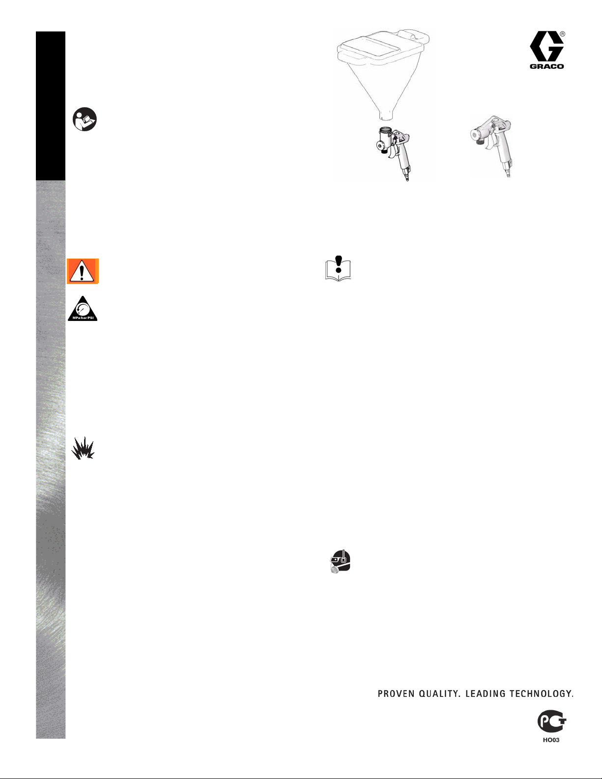
Texture Guns
Models: 288628, 288629, and 245924
125 psi (8.75 bar, 0.875 MPa) Maximum Air Working Pressure
70 psi (4.9 bar, 0.49 MPa) Maximum Fluid Working Pressure
311777D
IMPORTANT SAFETY INSTRUCTIONS. Refer to your
sprayer instruction manual for Pressure Relief, priming and
spray instructions. Keep these instructions.
English
Model
288628,
no hopper
Model
245924,
with hopper
ti8808a
Model
288629
ti8508a
- For Water-Based Materials Only -
The following Warnings are for the setup, use, grounding, maintenance and repair of this equipment. The exclamation point
symbol alerts you to a general warning and hazard symbols refer to procedure-specific risks. Refer back to these Warnings.
Additional, product-specific warnings may be found throughout the body of this manual where applicable.
EQUIPMENT MISUSE HAZARD
WARNINGS
PRESSURIZED EQUIPMENT HAZARD
Fluid from the gun/dispense valve, leaks, or ruptured
components can splash in the eyes or on skin and
cause serious injury.
• Follow Pressure Relief Procedure in this manual when
you stop spraying and before cleaning, checking, or
servicing equipment.
• Tighten all fluid connections before operating the
equipment.
• Check hoses, tubes, and couplings daily. Replace worn
or damaged parts immediately.
FIRE AND EXPLOSION HAZARD
Flammable fumes, such as solvent and paint fumes,
in work area can ignite or explode. To help prevent
fire and explosion:
• Use equipment only in well ventilated area.
• Eliminate all ignition sources; such as pilot lights, cigarettes, portable electric lamps, and plastic drop cloths
(potential static arc).
• Keep work area free of debris, including solvent, rags
and gasoline.
• Do not plug or unplug power cords, or turn power or light
switches on or off when flammable fumes are present.
• Ground all equipment in the work area. See Grounding
instructions.
• Use only grounded hoses.
• Hold gun firmly to side of grounded pail when triggering
into pail.
• If there is static sparking or you feel a shock, stop oper-
ation immediately. Do not use equipment until you identify and correct the problem.
• Keep a working fire extinguisher in the work area.
Misuse can cause death or serious injury.
• Do not operate the unit when fatigued or under the influence of drugs or alcohol.
• Do not exceed the maximum working pressure or temperature rating of the lowest rated system component.
See Technical Data in all equipment manuals.
• Use fluids that are compatible with equipment wetted
parts. See Technical Data in all equipment manuals.
Read fluid manufacturer’s warnings. For complete information about your material, request MSDS forms from
distributor or retailer.
• Check equipment daily. Repair or replace worn or damaged parts immediately with genuine manufacturer’s
replacement parts only.
• Do not alter or modify equipment.
• Use equipment only for its intended purpose. Call your
distributor for information.
• Route hoses and cables away from traffic areas, sharp
edges, moving parts, and hot surfaces.
• Do not kink or over bend hoses or use hoses to pull
equipment.
• Keep children and animals away from work area.
• Comply with all applicable safety regulations.
PERSONAL PROTECTIVE EQUIPMENT
You must wear appropriate protective equipment
when operating, servicing, or in the operating area
of the equipment to help protect you from serious
injury. This equipment includes but is not limited to:
• Protective eyewear
• Clothing and respirator as recommended by the fluid and
solvent manufacturer
•Gloves
• Hearing protection
Graco Inc. P.O. Box 1441 Minneapolis, MN 55440-1441
Copyright 2006, Graco Inc. is registered to I.S. EN ISO 9001
Repair
Page 2
Pressure Relief Procedure
WARNING
Follow this Pressure Relief Procedure whenever
you are instructed to relieve pressure, stop spraying,
check or service equipment or install or clean spray
tip.
1. Turn OFF power and turn sprayer pressure control to
lowest pressure setting.
2. Trigger gun into pail to relieve pressure.
Cleaning and Lubricating
Disassemble needle assembly and clean and grease o-rings
regularly to prolong gun life.
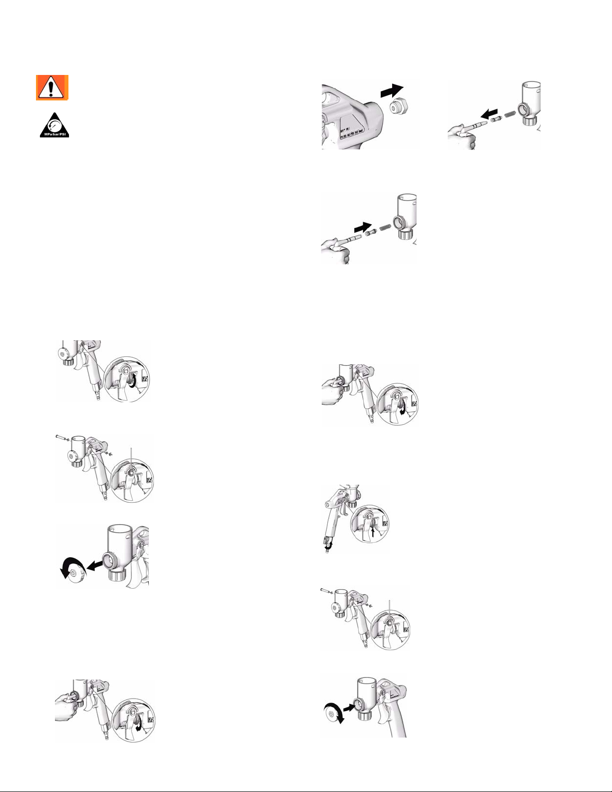
Disassembly
1. Perform Pressure Relief Procedure (see above).
2. Remove hopper or material hose from gun.
3. Clean off as much material on gun body as possible.
4. Turn flow adjustment nut counter-clockwise to enable
trigger to have full range of travel.
9. Remove plug and use small screwdriver to remove all
components out front of gun.
ti8807a
ti8806a
Assembly
1. Hold gun as shown and insert spring in front of gun.
ti9271a
2. Insert spring guide with o-ring into flow adjustment nut.
Make sure the protruded end of the guide points out as
shown.
3. Position flow adjustment nut in seat on gun body.
4. Apply a generous amount of grease to o-rings.
5. Rest gun on air connection fitting. Slide needle into front
of gun.
ti8539a
5. Using a small flat screwdriver, pry retaining ring off of
trigger pin. Remove pin, washer, and trigger.
ti8530a
6. Unscrew nozzle and remove it from gun.
ti9273a
7. Hold needle securely in place so it does not turn while
turning flow control clockwise until needle is disengaged
from thread and released. Pull needle and o-rings out
front of gun.
8. Hold hand under trigger area to catch adjustment nut,
spring retainer, and spring. Tap gun lightly to loosen
spring or use a small screwdriver to loosen.
ti8538a
6. While pushing needle into gun, turn flow adjustment nut
counter-clockwise to tighten needle.
7. Pull back on flow adjustment nut or continue pushing
needle in to make room for trigger.
ti8532a
8. Insert pin through trigger and washers. Push the retaining
clip onto the pin.
ti8530a
9. Pull trigger and replace nozzle.
ti8538a
2 311777D
ti9272a
Page 3

Parts
Model 288628 and 245924
31
33
16a
26
20
8
(a,b,c,d)
3a
21
3d
3d
3e
27
1B
10
9
Model 288629
3f
20
21
3d
6
22
21
2
3a
8
(a,b,c,d)
32
3f
3d
22
ti8524a
3c
3e
1A
27
10
16c
3b
21
16b
2
6
9
3c
3b
ti8509a
Ref. Part Description Qty
A 288628 GUN, complete, (for use with hopper)
B 288629 GUN, complete, (non-hopper)
1A 277393 BODY, gun
1B 277394 BODY, gun
2 15F913 TRIGGER, gun, trigger
3 258000 KIT, needle, repair
includes 3a, 3b, 3c, 3d, 3e, 3f
3a NEEDLE, includes o-ring
3b NUT, flow adjuster
3c GUIDE, needle
3d O-RING
3e SPRING
3f TAPE, foam
6 15B168 LOCK, trigger
8 234153 KIT, nozzle, includes 8a, 8b, 8c, 8d
8a NOZZLE, fine, beige
Ref. Part Description Qty
9 169970 FITTING, line air
1
10 15B565 VALVE, ball
1
16 234162 KIT, plug, includes 16a, 16b, 16c
1
16a PLUG, hopper
1
16b PLUG, hose, port
1
16c O-RING
1
20 118717 PIN, clevis w/ring groove
21 107243 WASHER
22 115999 RING, retaining
26 287967 PIN, clip gun
27 15J635 PLUG
31 234225 KIT, hopper, 1.5 gallon (includes 32)
32 234188 CLAMP
33 234222 KIT, hopper, 0.75 gallon (includes 32)
1
1
Technical Data
8b NOZZLE, small, white
8c NOZZLE, medium, gray
8d NOZZLE, large, black
Air Consumption 3.5-11 cfm at 15 to 100 psi
Weight 35 oz (1600 g)
311777D 3
1
1
1
1
2
1
1
1
1
1
Page 4

All written and visual data contained in this document reflects the latest product information available at the time of publication.
Graco reserves the right to make changes at any time without notice.
This manual contains English. MM 311777
Graco Headquarters: Minneapolis
International Offices: Belgium, China, Japan, Korea
GRACO INC. P.O. BOX 1441 MINNEAPOLIS, MN 55440-1441
www.graco.com
311777D
Revised 09/2007
 Loading...