

Page 1
Instructions
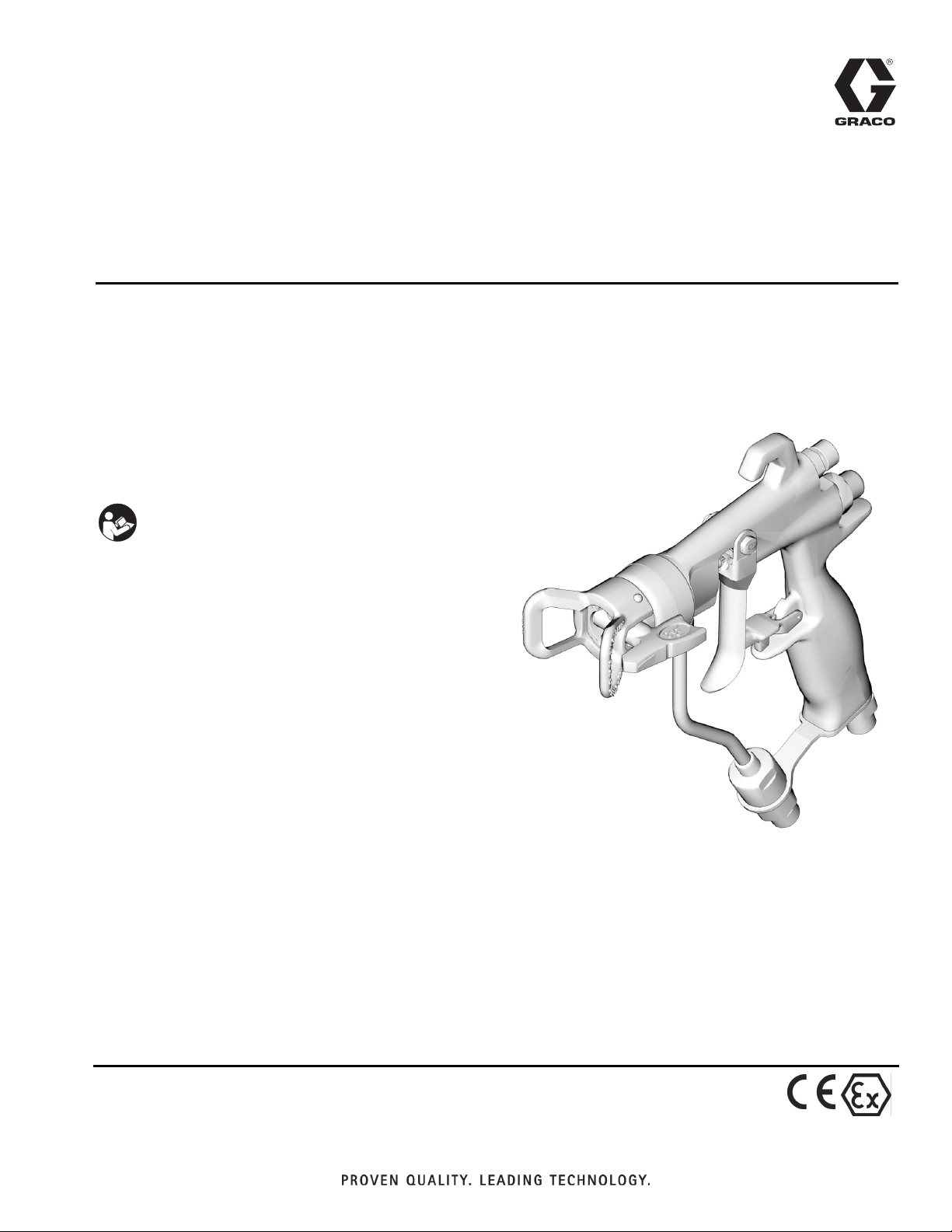
G40 Air Assisted Spray Gun
For the application of architectural paints and coatings. For professional use only.
Model: 288513, 289604
Maximum Working Pressure: 4000 psi (280 bar, 28 MPa)
Maximum Air Working Pressure: 100 psi (7 bar, 0.7
MPa)
IMPORTANT SAFETY INSTRUCTIONS. Refer to your
sprayer instruction manual for Pressure Relief, priming and
spray instructions. Keep these instructions.
311937G
EN
ti8835a
Page 2
Warnings
Warnings
The following Warnings are for the setup, use, grounding, maintenance and repair of this equipment. The
exclamation point symbol alerts you to a general warning and hazard symbols refer to procedure-specific risks. Refer
back to these Warnings. Additional, product-specific warnings may be found throughout the body of this manual
where applicable.
WARNING
WARNINGWARNINGWARNING
SKIN INJECTION HAZARD
High-pressure fluid from gun, hose leaks, or ruptured components will pierce skin. This may look like just a
cut, but it is a serious injury that can result in amputation. Get immediate surgical treatment.
• Do not point gun at anyone or at any part of the body.
• Do not put your hand over the spray tip.
• Do not stop or deflect leaks with your hand, body, glove, or rag.
• Do not spray without tip guard and trigger guard installed.
• Engage trigger lock when not spraying.
Follow Pressure Relief Procedure in this manual, when you stop spraying and before cleaning, checking,
or servicing equipment.
FIRE AND EXPLOSION HAZARD
Flammable fumes, such as solvent and paint fumes, in work area can ignite or explode. To help prevent
fire and explosion:
• Use equipment only in well ventilated area.
• Eliminate all ignition sources; such as pilot lights, cigarettes, portable electric lamps, and plastic drop
cloths (potential static arc).
• Keep work area free of debris, including solvent, rags and gasoline.
• Do not plug or unplug power cords, or turn power or light switches on or off when flammable fumes are
present.
• Ground all equipment in the work area. See Grounding instructions.
• Use only grounded hoses.
• Hold gun firmly to side of grounded pail when triggering into pail.
• If there is static sparking or you feel a shock, stop operation immediately. Do not use equipment until
you identify and correct the problem.
• Keep a working fire extinguisher in the work area.
EQUIPMENT MISUSE HAZARD
Misuse can cause death or serious injury.
• Do not operate the unit when fatigued or under the influence of drugs or alcohol.
• Do not exceed the maximum working pressure or temperature rating of the lowest rated system component. See Technical Data in all equipment manuals.
• Use fluids and solvents that are compatible with equipment wetted parts. See Technical Data in all
equipment manuals. Read fluid and solvent manufacturer’s warnings. For complete information about
your material, request MSDS forms from distributor or retailer.
• Check equipment daily. Repair or replace worn or damaged parts immediately with genuine manufacturer’s replacement parts only.
• Do not alter or modify equipment.
• Use equipment only for its intended purpose. Call your distributor for information.
• Route hoses and cables away from traffic areas, sharp edges, moving parts, and hot surfaces.
• Do not kink or over bend hoses or use hoses to pull equipment.
• Keep children and animals away from work area.
• Comply with all applicable safety regulations.
2 311937G
Page 3
Warnings
WARNING
WARNINGWARNINGWARNING
PRESSURIZED ALUMINUM PARTS HAZARD
Do not use 1,1,1-trichloroethane, methylene chloride, other halogenated hydrocarbon solvents or fluids
containing such solvents in pressurized aluminum equipment. Such use can cause serious chemical
reaction and equipment rupture, and result in death, serious injury, and property damage.
PERSONAL PROTECTIVE EQUIPMENT
You must wear appropriate protective equipment when operating, servicing, or in the operating area of the
equipment to help protect you from serious injury. This equipment includes but is not limited to:
• Protective eyewear
• Clothing and respirator as recommended by the fluid and solvent manufacturer
• Gloves
• Hearing protection
311937G 3
Page 4

Warnings
Pressure Relief Procedure
Follow this Pressure Relief Procedure whenever instructed
to relieve pressure, stop spraying, check or service equipment,
or install or clean spray tip.
1. Lock trigger. Turn OFF power and turn pressure control to
lowest pressure setting.
2. Unlock trigger. Hold gun against side of flushing pail.
Trigger gun into pail to relieve pressure.
If you suspect spray tip or hose is clogged or that pressure has
not been fully relieved after following the steps above, VERY
SLOWLY loosen tip guard retaining nut or hose end coupling
to relieve pressure gradually, then loosen completely. Clear
hose or tip obstruction.
Gun Trigger Lock
To prevent injury when the gun is not in use, always lock the
trigger if unit is being shut down or left unattended.
Trigger Locked
(no spray)
Trigger Unlocked
(spray)
2. For Air-Assisted spraying,
black, coiled, air supply hose (a) to gun
air inlet fitting (17).
NOTE: The first time you set up the gun
for spraying you will have to cut the
black air hose to length desired.
3. Attach blue fluid supply hose (b) to gun
fluid inlet fitting(25).
4. Attach other end of air and fluid supply
hoses to sprayer. Use two wrenches to
tighten all connections securely (see
sprayer setup instructions in sprayer
operation manual 311905.)
first attach
a
ti9022a
25
b
Installing Tip (33) and Guard (6) on Gun
1. If equipment has recently been operated, relieve pressure.
2. Insert seat housing (35)
into guard (6).
3. Insert SwitchTip (33).
4. Insert seal (33b) over seat
(35a) and insert in seat
housing (25). Use black
seal for water-based materials and orange for solvent and
oil-based materials.
5. Install guard (6) over end of gun. Hand tighten.
If you notice fluid leaking from front of gun, replace the
seat (33a) and/or retighten the guard nut.
6
ti8249a
35
33a
33
17
33b
ti6581a ti6582a
Setup
Make sure sprayer is turned off and unplugged from power
source and trigger lock is locked. Refer to your sprayer
instruction manual for priming and spray instructions.
Operation
Note: The following instructions are for guns used with
Graco’s FinishPro Sprayers. See the sprayer instruction
manual 311905. If you are using a different sprayer, see your
equipment instruction manual.
If you are using a FinishPro
regulation is only provided at the gun. The FinishPro
Model Sprayers provide additional air regulation at the
sprayer.
™
390 Model Sprayer, air
™
395
Connect Gun to Sprayer
1. Attach air inlet fitting (17) and fluid
inlet fitting (25) to gun.
1. Unlock trigger (1a).
17
25
ti9444a
4 311937G
2. Be sure the arrow shaped tip (33) faces forward (spray).
3. Hold gun perpendicular and approximately 12-inches
(304 mm) from surface. Move gun first, then pull gun
trigger (3) to spray a test pattern.
4. Always hold gun at a right angle from the surface. Do not
make an arc with the gun. This causes an uneven coat of
fluid. To obtain an even finish, use smooth, even strokes
across the object being sprayed with a 50% overlap.
Page 5

Warnings
Clearing a Clog
1. Relieve pressure. Lock trigger (1a).
2. Rotate tip (33) 180°. Unlock trigger (1a). Trigger gun into
pail or onto ground to remove clog.
3. Lock trigger (1a). Rotate tip (33) 180° back to spray
position.
Spraying
Refer to your Sprayer Instruction manual. The following
instructions are for guns used with Graco’s FinishPro
Sprayers.
Air-Assisted Spraying
1. Set sprayer function selection switch to AIRLESS spraying.
2. Open gun air pressure regulator all the way.
3. Prime pump following priming instructions provided in
sprayer operation manual 311905.
4. Turn sprayer fluid pressure control to highest setting.
5. Unlock trigger (1a). While triggering gun, turn down
sprayer fluid pressure until you notice tails forming in
spray pattern.
6. Stop triggering gun.
7. Set sprayer toggle switch to AA (Air Assisted) spraying.
8. Trigger gun. While spraying increase gun air pressure
regulator until tails disappear.
9. Use gun air regulator to fine tune spray pattern.
Airless Spraying
1. Set sprayer function selection switch to AIRLESS spraying.
2. Prime pump following priming instructions provided in
sprayer operation manual 311905.
3. Start with sprayer pressure turned to lowest setting.
4. Spray a test pattern. Gradually increase sprayer pressure
until you achieve a consistent spray pattern, without
heavy edges. Use a smaller tip if pressure adjustment
alone does not eliminate edges.
Note: If you are getting an irregular spray
pattern, clean air holes with solvent and
a soft brush or toothpick. Do not use
metal tools to clean the air cap holes as
this may scratch them. Scratches can
distort the spray pattern.
TI8792a
Maintenance
Before performing any maintenance on gun, read all warnings
on front cover of this manual and relieve pressure, page 4.
Daily Maintenance
Flush gun after each work shift and store in a dry location.
Do not immerse the gun or any parts in water or cleaning
solvents.
• Do not point gun up while cleaning it.
• Do not wipe gun with cloth soaked in solvent; wring out
excess.
• Solvent left in gun air passages could result in a poor
quality paint finish. Do not use any cleaning method that
may allow solvent into gun air passages.
Flushing and Cleaning
• Flush gun before changing colors, before storing and before
repairing gun.
• Flush at lowest possible pressure. Check connectors for
leaks and tighten as necessary.
• Flush with fluid that is compatible with fluid being dispensed
and equipment’s wetted parts.
1. Relieve pressure, page 4. Unplug sprayer from outlet.
2. Remove tip (33) and guard (6).
3. Disconnect black air supply hose from gun.
4. Remove sprayer siphon tube set from paint and place in
flushing fluid. See Cleanup instructions in sprayer
operation manual 311905.
5. Plug sprayer in outlet. Set sprayer function selection
switch to AIRLESS.
6. Increase pressure slowly. Point gun down into a grounded
metal container. Pull gun trigger and flush gun with
solvent until all traces of fluid are removed from gun
passages.
7. Turn sprayer function selection switch to OFF.
8. Relieve pressure, page 4.
9. Disconnect fluid supply hose from gun.
10. If it is necessary to remove diffuser (5) to clean, trigger
gun while you remove the diffuser with the gun tool (30).
11. Dip the soft end of a soft-bristle brush into a compatible
solvent. Do not continuously soak the brush’s bristles
with solvent and do not use a wire brush.
12. With gun pointed down, clean front of the gun with the
soft-bristle brush and solvent.
13. Scrub the tip (33) and guard (6) with soft-bristle brush. To
clean out air cap holes, use a soft tool such as a
toothpick, to avoid damaging critical surfaces. Blow air
through the spray tip to ensure the orifice is clean.
311937G 5
Page 6

Warnings
14. If the diffuser (5) was removed, trigger the gun while you
reinstall the diffuser with the gun tool (30). Tighten the
diffuser securely to obtain a good seal. Torque to 155-165
in-lb (18-19 N.m). When properly tightened, the flange will
bottom out on the gun.
15. Install tip (33) and guard (6) on gun, page 4.
16. Using a soft cloth dampened in solvent, wipe off outside of
gun.
17. After cleaning, lubricate the
following parts weekly with
lubricant 111265.
A
• Trigger pivot pin (A)
• Both sides of gun where
trigger contacts gun (B)
• Fluid needle shaft, behind
trigger (C)
B
ti8835a
C
Cleaning/Replacing Filter (24)
1. Relieve pressure, page 4. Lock trigger (1a).
2. Unscrew fluid inlet fitting (25).
3. Remove inline fluid filter (24).
4. Clean filter with soft brush and compatible solvent.
Inspect filter and if damaged, replace it.
5. Install inline fluid filter (24) into base of fluid tube (16).
6. Screw fluid inlet fitting (25) into base of tube. Torque to
175-185 in-lb (20-21 N•m).
Repair
Seat Repair
Use Carbide Seat Repair Kit - 249456. For best results use all
new parts provided in kit.
1. Relieve the pressure, page 4. Remove the fluid and air
hoses from the gun.
2. Remove the guard (6) and spray tip (33).
3. Trigger gun to pull the needle housing off the seat while
you unscrew the diffuser (5) from the gun body (1), using
gun tool (30).
4. Inspect o-rings (5e, 5f, and 6a) in place. Carefully remove
the o-rings from the diffuser housing (5a) and replace if
necessary.
5. Remove the seat nut (5d), seat (5c) and seat gasket (5b)
using a 7/32 in. hex wrench.
6. Inspect seat (5c) and seat gasket (5b) and replace if
necessary.
7. Reinstall the seat gasket (5b) seat (5c) and seat nut (5d).
Torque to 45-50 in-lb (5.0-5.6 N•m). Be sure not to
overtighten nut.
• When reinstalling the carbide seat (5c), the tapered end
of the seat must point toward the gun tip.
Needle Repair (2)
1. Relieve pressure, page 4. Remove the diffuser (5), see
Seat Repair, page 6.
2. Remove the trigger pivot pin
nut (14), pivot pin (13), and
trigger (3) using the gun tool
(30) and nut driver (29).
13
3
TI6574A
3. Remove the fluid
needle assembly
(2) from the front of
2a
2
the gun by using
the nut driver tool
(29). If the needle
is bent or
29
ti6575a
damaged, or the
packing is worn or
leaking, replace the entire needle assembly. If
replacement is necessary, be sure to remove the o-ring
(2a) as it may stick inside the gun body.
Air Valve Repair (8)
1. Unscrew the spring cap (11) from the back of the gun
body (1) using the gun tool (30). Remove the two springs
(15 and 19), the shaft (9), and seat (10).
2. Push the air valve assembly (8) out the back of the gun.
3. Inspect the u-cup (7) in the gun body (1). If the u-cup is
worn or leaking, carefully remove the u-cup from the front
of the gun body, using a pick.
8
1
TI6577A
7
15
11
19
10
9
14
6 311937G
Page 7

Warnings
Fluid Tube Replacement (16)
1. Remove the air inlet fitting
(17) using the gun tool (30)
and remove the screw (20)
using a 3/16 in. hex wrench.
2. Unscrew the fluid inlet fitting
(25). Remove and clean or
replace the inline fluid filter
(24).
3. Unscrew fluid tube connector
(16a) from fluid inlet. Carefully
remove gasket (22).
Flat Tip Conversion Kit
(Optional)
The Flat Tip Conversion Kit allows
22
16a
16
24
25
ti6573a
17
AAM Flat Tips to be used with this
gun. Order part number 288514.
Reassembly
1. Install the tube gasket (22) in the gun. Hand tighten the
fluid tube connector (16a) into the gun’s fluid inlet. Antigens the air inlet fitting (17) and screw (20). Torque the
fluid tube connector to 150-160 in-lb (17-18 N•m). Torque
the air inlet fitting to 175-185 in-lb (20-21 N•m). Torque
the fluid tube bracket screw to 50-60 in-lb (6-7 N•m).
2. Install the inline fluid filter (24) into the base of the fluid
tube (16). Screw the fluid inlet fitting (25) into the base of
the tube. Torque to 175-185 in-lb (20-21 N•m).
3. Place the new u-cup (7) on the seal installation tool (28),
with the u-cup lips facing the tool. Push the u-cup into the
back of the gun until you feel a definite snap.
6. Install the two springs (15 and 19). Screw the spring cap
(11) into the back of the gun body. Torque to 175-185
in-lb (20-21 N•m).
7. Lightly lubricate the needle assembly o-rings and shaft
where the packing slides. Be sure that the o-ring (2a) is in
place in the gun body (1).
8. Insert the fluid needle assembly (2) into the front of the
gun. Use the nut driver (29) to screw the fluid needle
assembly into the gun body (1) and torque to 50-60 in-lb
(6-7 N•m).
1
2a
2
29
20
ti6575a
9. Install the trigger (3), pivot pin (13), and nut (14). Use low
strength thread locker and be sure that the brass piece of
the fluid needle assembly (2) is behind the trigger.
Lubricate both sides of the pivot pin where the trigger
contacts the pin and lubricate the boss on both sides of
the gun where the trigger contacts the gun body. Torque
the nut to 20-30 in-lb (2-3 N•m).
10. Trigger the gun to pull the needle back while you screw
the diffuser assembly (5) into the gun body (1) using the
gun tool (30). Torque to 155-165 in-lb (18-19 N•m). When
properly tightened, the flange will bottom out on the gun.
11. Attach the guard (6) and spray tip (33), page 4.
3
Lubricate lightly.
8
Lips face out of gun body.
7
8
3
28
ti6578a
4. Lubricate the front end of the air valve assembly (8).
Gently slide the air valve assembly into the back of the
gun, passing through the u-cup (7), as far as it will go. Be
careful not to damage the u-cup.
5. Slide the seat (10) onto the shaft (9). Be sure that the
Tranlated Manuals
Spanish - 311939 Estonian - 311957
French - 311938 Latvian - 311958
Dutch - 311941 Lithuanian - 311956
German - 311950 Polish - 311951
Italian - 311940 Hungarian - 311954
Turkish - 311942 Czech - 311953
Greek - 311943 Slovakian - 311959
Croatian - 311955 Portuguese - 311944
Danish - 311948 Finnish - 311946
Chinese - 311960 Swedish - 311947
Japanese - 311961 Norwegian - 311949
Korean - 311962 Russian - 311952
Translated manuals can be obtained from a distributor
or by visiting www.graco.com.
tapered end of the seat is toward the thicker end of the
shaft. Carefully insert the shaft (9) and seat (10) in the air
valve (8).
311937G 7
Page 8

Parts
Parts
33
5e
33b
5a
5f
35
33a
6a
6
2a
2
22
13
5b
5c
7
5d
15
11
4
8
19
10
9
1
1a
14
3
29
30
16
36
24
25
Ref. Part No. Description Qty.
24a
1 BODY, gun, assy 1
1a 249423 SAFETY, trigger 1
2◆ NEEDLE, assy; 3/32 carbide ball;
includes item 2a
2a* 110004 PACKING, o-ring; PTFE 1
3 249585 KIT, trigger, repair, includes 13 and 14 1
4 15G713 NUT, air plug 1
5 249877 DIFFUSER, assy, RAC 1
5a DIFFUSER, housing 1
5b◆ GASKET, seat; nylon 1
5c◆ SEAT; carbide 1
5d◆ NUT, seat 1
5e* 111457 PACKING, o-ring, seat; PTFE 1
5f* 109450 PACKING, o-ring; PTFE 1
6 288839 GUARD, RAC 1
6a* 109213 PACKING, o-ring, PTFE 1
7* 188493 PACKING, u-cup, gun; UHMWPE 1
8* VALVE, air, assy 1
9 15F193 SHAFT, fluid spring 1
10 15F194 SEAT, spring 1
11 15F195 CAP, spring 1
12 288715 VALVE, swivel with hose fitting 1
13 15F739 PIN, pivot 1
14 15F740 PIN, pivot, nut 1
15 114069 SPRING, compression 1
16 249136 TUBE, assy 1
17 15F202 FITTING, air inlet 1
17
20
Ref. Part No. Description Qty.
12
ti7203d
22* 115133 GASKET, tube, acetal 1
24 224453 FILTER 1
24a‡ 162863 GASKET, non-metallic (sold separately)
1
25 15F186 FITTING, fluid inlet 1
28* TOOL, installation; seal 1
29 117642 TOOL, nut driver 1
30 15F446 TOOL, gun 1
31▲ 222385 CARD, warning (not shown) 1
32▲ 172479 TAG, warning (not shown) 1
33 FFT210 SPRAY TIP (288513) 1
FFA210 SPRAY TIP (289604) 1
33a** SEAT, gasket 1
33b** SEAL 1
35† 15J770 HOUSING, cylinder 1
36 239663 SWIVEL 1
▲Replacement Danger and Warning labels, tags, and cards are
available at no cost.
◆ Included in Needle/Seat Repair Kit 255160 (purchase separately)
† Included in RAC Guard Kit 288839
*Included in Seal Repair Kit 249422 (purchase separately)
‡ If you want to remove the filter, order 162863 to use as a seal in its
place.
**Included in 246453 RAC X One Seal Kit (Standard)
**Included in 248936 RAC X One Seal Kit (Solvent)
28
19 115141 SPRING, compression 1
20 119996 SCREW, cap, socket hd; 1/4-20 x 3/8 in.
1
(10 mm)
8 311937G
Page 9

Technical Data
Technical Data
Maximum Working Fluid Pressure..............................................................4000 psi (28 MPa, 280 bar)
Maximum Working Air Pressure.................................................................100 psi (0.7 MPa, 7 bar)
Maximum Working Fluid Tempera-
ture........................................................
Fluid inlet.................................................................................................... 1/4-18 npsm
Air Inlet....................................................................................................... 1/4-18 npsm
Gun
Weight.................................................................................................
Sound Pressure*: 20 psi (140 kPa, 1.4 bar)...............................................66.9 dB(A)
Sound Pressure*: 100 psi (0.7 kPa, 7 bar).................................................80.0 dB(A)
Sound Power*: 20 psi (140 kPa, 1.4 bar)....................................................76.8 dB(A)
Sound Power*: 100 psi (0.7 kPa, 7 bar)......................................................89.9 dB(A)
Wetted Parts: Stainless Steel, Carbide, Ultra High Molecular Weight Polyethylene, Acetal, PTFE, Nylon, Flouroelastomer
110° F (43° C)
16 oz (450 grams)
*All readings were taken with fan valve fully closed, (full fan size) at 20 psi (140 kPa, 1.4 bar) and 100 psi (0.7 kPa, 7
bar) and at the assumed operator position. Sound Power tested to ISO 9614-2.
311937G 9
Page 10

Graco Standard Warranty
Graco warrants all equipment referenced in this document which is manufactured by Graco and bearing its name to be free from defects in
material and workmanship on the date of sale to the original purchaser for use. With the exception of any special, extended, or limited warranty
published by Graco, Graco will, for a period of twelve months from the date of sale, repair or replace any part of the equipment determined by
Graco to be defective. This warranty applies only when the equipment is installed, operated and maintained in accordance with Graco’s written
recommendations.
This warranty does not cover, and Graco shall not be liable for general wear and tear, or any malfunction, damage or wear caused by faulty
installation, misapplication, abrasion, corrosion, inadequate or improper maintenance, negligence, accident, tampering, or substitution of
non-Graco component parts. Nor shall Graco be liable for malfunction, damage or wear caused by the incompatibility of Graco equipment with
structures, accessories, equipment or materials not supplied by Graco, or the improper design, manufacture, installation, operation or maintenance
of structures, accessories, equipment or materials not supplied by Graco.
This warranty is conditioned upon the prepaid return of the equipment claimed to be defective to an authorized Graco distributor for verification of
the claimed defect. If the claimed defect is verified, Graco will repair or replace free of charge any defective parts. The equipment will be returned
to the original purchaser transportation prepaid. If inspection of the equipment does not disclose any defect in material or workmanship, repairs will
be made at a reasonable charge, which charges may include the costs of parts, labor, and transportation.
THIS WARRANTY IS EXCLUSIVE, AND IS IN LIEU OF ANY OTHER WARRANTIES, EXPRESS OR IMPLIED, INCLUDING BUT NOT LIMITED
TO WARRANTY OF MERCHANTABILITY OR WARRANTY OF FITNESS FOR A PARTICULAR PURPOSE.
Graco’s sole obligation and buyer’s sole remedy for any breach of warranty shall be as set forth above. The buyer agrees that no other remedy
(including, but not limited to, incidental or consequential damages for lost profits, lost sales, injury to person or property, or any other incidental or
consequential loss) shall be available. Any action for breach of warranty must be brought within two (2) years of the date of sale.
GRACO MAKES NO WARRANTY, AND DISCLAIMS ALL IMPLIED WARRANTIES OF MERCHANTABILITY AND FITNESS FOR A
PARTICULAR PURPOSE, IN CONNECTION WITH ACCESSORIES, EQUIPMENT, MATERIALS OR COMPONENTS SOLD BUT NOT
MANUFACTURED BY GRACO. These items sold, but not manufactured by Graco (such as electric motors, switches, hose, etc.), are subject to
the warranty, if any, of their manufacturer. Graco will provide purchaser with reasonable assistance in making any claim for breach of these
warranties.
In no event will Graco be liable for indirect, incidental, special or consequential damages resulting from Graco supplying equipment hereunder, or
the furnishing, performance, or use of any products or other goods sold hereto, whether due to a breach of contract, breach of warranty, the
negligence of Graco, or otherwise.
FOR GRACO CANADA CUSTOMERS
The Parties acknowledge that they have required that the present document, as well as all documents, notices and legal proceedings entered into,
given or instituted pursuant hereto or relating directly or indirectly hereto, be drawn up in English. Les parties reconnaissent avoir convenu que la
rédaction du présente document sera en Anglais, ainsi que tous documents, avis et procédures judiciaires exécutés, donnés ou intentés, à la suite
de ou en rapport, directement ou indirectement, avec les procédures concernées.
Graco Information
For the latest information about Graco products, visit www.graco.com.
TO PLACE AN ORDER, contact your Graco distributor or call 1-800-690-2894 to identify the nearest distributor.
All written and visual data contained in this document reflects the latest product information available at the time of publication.
GRACO INC. AND SUBSIDIARIES • P.O. BOX 1441 • MINNEAPOLIS MN 55440-1441 • USA
Copyright 2006, Graco Inc. All Graco manufacturing locations are registered to ISO 9001.
Graco reserves the right to make changes at any time without notice.
For patent information, see www.graco.com/patents
2ULJLQDOLQVWUXFWLRQV This manual contains English. MM 311937
Graco Headquarters: Minneapolis
International Offices: Belgium, China, Japan, Korea
www.graco.com
Revised 5/2013
 Loading...