

Page 1
Instructions - Parts
Automatic G40 Air-Assisted
Spray Guns
For air-assisted spraying of paints and coatings. For professional use only.
Approved for use in explosive atmospheres.
4000 psi (28 MPa, 280 bar) Maximum Working Fluid Pressure
100 psi (0.7 MPa, 7 bar) Maximum Working Air Pressure
See page 3 for model information.
Important Safety Instructions
Read all warnings and instructions in this manual.
Save these instructions.
311052E
ENG
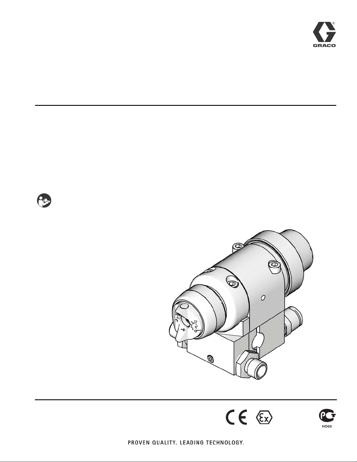
Part No. 288046 Spray Gun shown
mounted on Part No. 288217 Manifold
TI8087b
II 2 G c T6
Page 2

Related Manuals
Contents
Related Manuals . . . . . . . . . . . . . . . . . . . . . . . . . . . 2
Models . . . . . . . . . . . . . . . . . . . . . . . . . . . . . . . . . . . 3
Warnings . . . . . . . . . . . . . . . . . . . . . . . . . . . . . . . . . 4
Installation . . . . . . . . . . . . . . . . . . . . . . . . . . . . . . . . 6
Ventilate Spray Booth . . . . . . . . . . . . . . . . . . . . . 6
Configure Gun and Manifold . . . . . . . . . . . . . . . . 6
Install Air Fittings . . . . . . . . . . . . . . . . . . . . . . . . . 7
Ground System . . . . . . . . . . . . . . . . . . . . . . . . . . 7
Mount Gun . . . . . . . . . . . . . . . . . . . . . . . . . . . . . 8
Connect Air Line . . . . . . . . . . . . . . . . . . . . . . . . . 9
Connect Fluid Line . . . . . . . . . . . . . . . . . . . . . . 10
Setup . . . . . . . . . . . . . . . . . . . . . . . . . . . . . . . . . . . . 11
Flush Spray Gun . . . . . . . . . . . . . . . . . . . . . . . . 11
Select a Spray Tip and Air Cap . . . . . . . . . . . . . 11
Install a Spray Tip . . . . . . . . . . . . . . . . . . . . . . . 11
Position the Air Cap . . . . . . . . . . . . . . . . . . . . . 11
Air Cap Alignment Pin . . . . . . . . . . . . . . . . . . . . 11
Operation . . . . . . . . . . . . . . . . . . . . . . . . . . . . . . . . 12
Pressure Relief Procedure . . . . . . . . . . . . . . . . 12
Adjust Spray Pattern . . . . . . . . . . . . . . . . . . . . . 12
Apply Fluid . . . . . . . . . . . . . . . . . . . . . . . . . . . . 13
Maintenance . . . . . . . . . . . . . . . . . . . . . . . . . . . . . . 14
Daily Gun Care . . . . . . . . . . . . . . . . . . . . . . . . . 14
General System Maintenance . . . . . . . . . . . . . . 15
Flushing and Cleaning . . . . . . . . . . . . . . . . . . . . 15
Troubleshooting . . . . . . . . . . . . . . . . . . . . . . . . . . . 17
General Troubleshooting . . . . . . . . . . . . . . . . . . 17
Spray Pattern Troubleshooting . . . . . . . . . . . . . 19
Service . . . . . . . . . . . . . . . . . . . . . . . . . . . . . . . . . . 20
Disassembly . . . . . . . . . . . . . . . . . . . . . . . . . . . 20
Diffuser Seat Replacement . . . . . . . . . . . . . . . . 23
Reassembly . . . . . . . . . . . . . . . . . . . . . . . . . . . . 23
Parts . . . . . . . . . . . . . . . . . . . . . . . . . . . . . . . . . . . . 24
Notes . . . . . . . . . . . . . . . . . . . . . . . . . . . . . . . . . . . . 30
AAP Series Tip and Air Cap Selection Charts . . . 31
LTX Series RAC Tip Selection Charts . . . . . . . . . 32
RAC Switch Tips . . . . . . . . . . . . . . . . . . . . . . . . 33
Accessories . . . . . . . . . . . . . . . . . . . . . . . . . . . . . . 34
Dimensions . . . . . . . . . . . . . . . . . . . . . . . . . . . . . . . 36
Mounting Hole Layout . . . . . . . . . . . . . . . . . . . . . . 37
Mounting Hole Layout . . . . . . . . . . . . . . . . . . . . . . 38
Technical Data . . . . . . . . . . . . . . . . . . . . . . . . . . . . 39
Graco Standard Warranty . . . . . . . . . . . . . . . . . . . 40
Graco Information . . . . . . . . . . . . . . . . . . . . . . . . . 40
Related Manuals
The Automatic Air-Assisted Airless Spray Guns manual is available in the following languages. See the following
chart for specific language and part number.
Manual Language
Manual Language
311052
311651
311652
311653
311654
311655
311656
311657
English
Chinese
Danish
Dutch
Finnish
French
German
Italian
311658
311659
311660
311661
311662
311663
311664
Japanese
Korean
Norwegian
Polish
Russian
Spanish
Swedish
2 311052E
Page 3

Models
A manifold is required for each gun to be installed.
Refer to the Parts section for manifold information.
Models
G40 Standard Spray Gun, 288046, Series A
• High pressure spray gun with Carbide ball and Carbide seat.
• Includes AAP series tip of choice.
G40 Plastic Seat Spray Gun, 288044, Series B
• Medium pressure spray gun with SST ball and plastic seat; for acid catalyzed or thin fluids.
• Best results when used with non-abrasive fluids at
pressures below 1500 psi (10.5 MPa,105 bar).
• Includes AAP series tip of choice.
G40 RAC Spray Gun, 288053, Series A
• High pressure spray gun with AA Reverse-A-Clean
(RAC) assembly; and Carbide ball and Carbide
Seat.
• Includes LTX Series RAC tip of choice.
311052E 3
Page 4
Warnings
Warnings
The following warnings are for the setup, use, grounding, maintenance, and repair of this equipment. The exclamation point symbol alerts you to a general warning and the hazard symbol refers to procedure-specific risk. Refer back
to these warnings. Additional, product-specific warnings may be found throughout the body of this manual where
applicable.
WARNING
EQUIPMENT MISUSE HAZARD
Misuse can cause death or serious injury.
• Do not operate the unit when fatigued or under the influence of drugs or alcohol.
• Do not exceed the maximum working pressure or temperature rating of the lowest rated system
component. See Technical Data in all equipment manuals.
• Use fluids and solvents that are compatible with equipment wetted parts. See Technical Data in all
equipment manuals. Read fluid and solvent manufacturer’s warnings. For complete information
about your material, request MSDS forms from distributor or retailer.
• Check equipment daily. Repair or replace worn or damaged parts immediately with genuine manufacturer’s replacement parts only.
• Do not alter or modify equipment.
• Use equipment only for its intended purpose. Call your distributor for information.
• Route hoses and cables away from traffic areas, sharp edges, moving parts, and hot surfaces.
• Do not kink or over bend hoses or use hoses to pull equipment.
• Keep children and animals away from work area.
• Comply with all applicable safety regulations.
SKIN INJECTION HAZARD
High-pressure fluid from gun, hose leaks, or ruptured components will pierce skin. This may look like just
a cut, but it is a serious injury that can result in amputation. Get immediate surgical treatment.
• Do not point gun at anyone or at any part of the body.
• Do not put your hand over the spray tip.
• Do not stop or deflect leaks with your hand, body, glove, or rag.
• Follow Pressure Relief Procedure in this manual, when you stop spraying and before cleaning,
checking, or servicing equipment.
FIRE AND EXPLOSION HAZARD
Flammable fumes, such as solvent and paint fumes, in work area can ignite or explode. To help prevent
fire and explosion:
• Use equipment only in well ventilated area.
• Eliminate all ignition sources; such as pilot lights, cigarettes, portable electric lamps, and plastic drop
cloths (potential static arc).
• Keep work area free of debris, including solvent, rags and gasoline.
• Do not plug or unplug power cords, or turn power or light switches on or off when flammable fumes
are present.
• Ground all equipment in the work area. See Grounding instructions.
• Use only grounded hoses.
• Hold gun firmly to side of grounded pail when triggering into pail.
• If there is static sparking or you feel a shock, stop operation immediately. Do not use equipment
until you identify and correct the problem.
• Keep a working fire extinguisher in the work area.
4 311052E
Page 5
Warnings
WARNING
PRESSURIZED EQUIPMENT HAZARD
Fluid from the gun/dispense valve, leaks, or ruptured components can splash in the eyes or on skin and
cause serious injury.
• Follow Pressure Relief Procedure in this manual, when you stop spraying and before cleaning,
checking, or servicing equipment.
• Tighten all fluid connections before operating the equipment.
• Check hoses, tubes, and couplings daily. Replace worn or damaged parts immediately.
TOXIC FLUID OR FUMES HAZARD
Toxic fluids or fumes can cause serious injury or death if splashed in the eyes or on skin, inhaled, or
swallowed.
• Read MSDS’s to know the specific hazards of the fluids you are using.
• Store hazardous fluid in approved containers, and dispose of it according to applicable guidelines.
PERSONAL PROTECTIVE EQUIPMENT
You must wear appropriate protective equipment when operating, servicing, or when in the operating
area of the equipment to help protect you from serious injury, including eye injury, inhalation of toxic
fumes, burns, and hearing loss. This equipment includes but is not limited to:
• Protective eyewear
• Clothing and respirator as recommended by the fluid and solvent manufacturer
•Gloves
• Hearing protection
311052E 5
Page 6
Installation
Installation
Ventilate Spray Booth
Check and follow all National, State, and Local
codes regarding air exhaust velocity requirements.
Check and follow all local safety and fire codes.
Configure Gun and Manifold
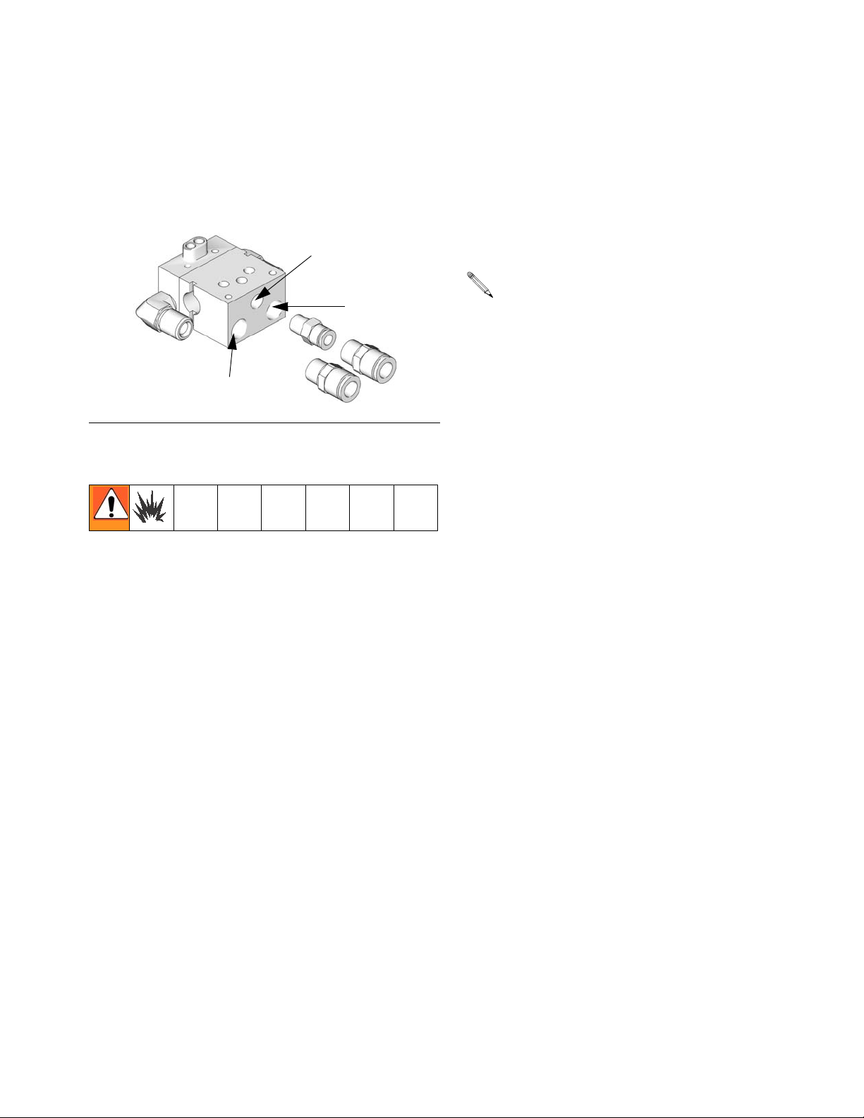
The gun is supplied with an internal fluid plug and seals
(5, 6, 7). To use the gun in a circulating system, remove
the internal plug. In a non-circulating system, leave the
plug in place to minimize flush time.
Circulating System
1. Apply anti-seize lubricant 222955 to the threads and
mating faces of the manifold (101) and the elbows
(107), supplied unassembled.
2. Install the elbows (107) in both fluid ports of the
manifold (101).
3. Connect the fluid supply line to one elbow and the
fluid return line to the other. The manifold fluid ports
are reversible.
4. Install the gun on the manifold, using the four
screws (17). Start the threads of all four screws, and
tighten the front two screws first, and then tighten
the back two screws to 65 in-lb (7.3 N•m).
Non-circulating System
1. See FIG. 1. Apply anti-seize lubricant 222955 to the
threads and mating faces of the manifold (101), plug
(109), and elbow (107), supplied unassembled.
2. Install an elbow (107) in one fluid port of the manifold (101), and a plug (109) in the other port.
3. Install the internal plug (5) in the gun fluid port on
the same side as the manifold plug.
4. Connect the fluid supply line to the manifold elbow
(107).
5. Install the gun on the manifold, using the four
screws (17). Start the threads of all four screws, and
tighten the front two screws first, and then tighten
the back two screws to 65 in-lb (7.3 N•m).
1
Remove when used in circulating systems.
2
Replace with a reducing nipple (107) when used in
circulating systems.
3
Install optional filter in fluid inlet port. See Accessories,
page 34.
7
3
6
101
5
2
1
109
107
TI8587b
FIG. 1: Non-Circulating Setup Shown (cutaway view)
6 311052E
Page 7
Installation
Install Air Fittings
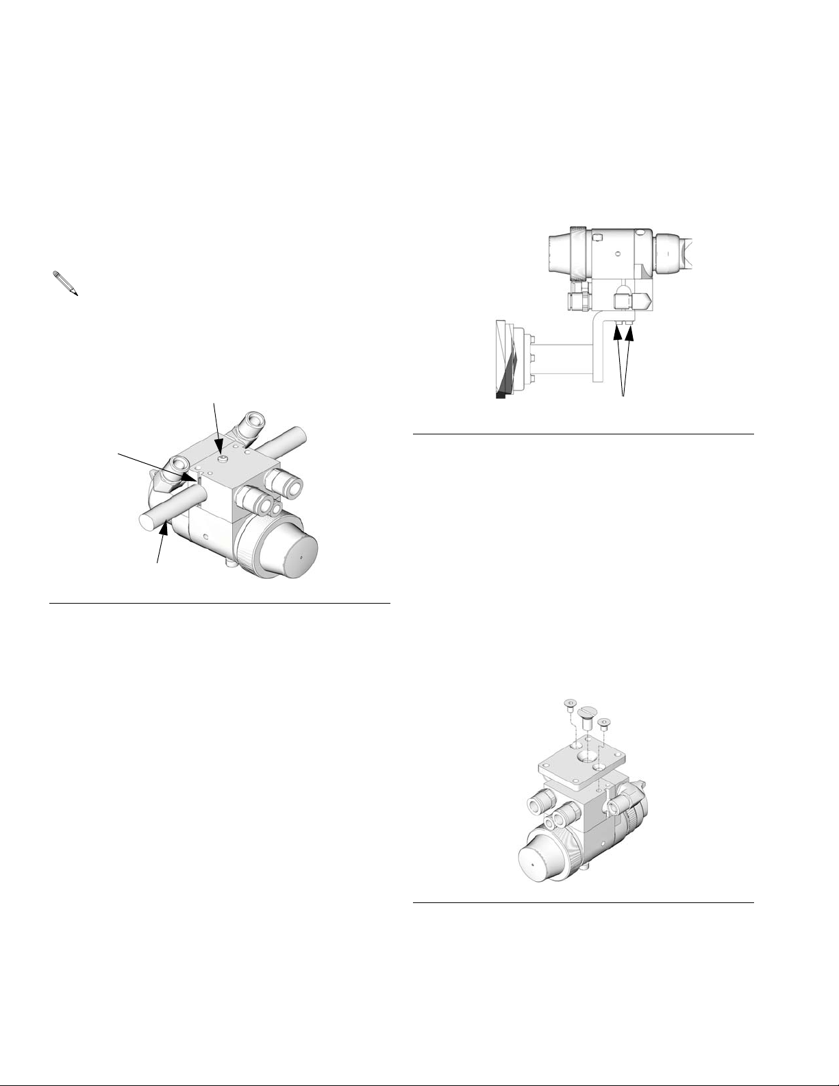
1. Install the supplied 1/4 in. tube fitting into the cylinder (CYL) air port.
2. Install 3/8 in. tube fittings into the atomization
(ATOM) air port and the fan (FAN) air port.
CYL
ATOM
TI8211a
F
IG. 2: Air Fittings
FAN
Ground System
Ground Air, Fluid, and Hydraulic Hoses
Connected To Pump
Use only electrically conductive hoses with a maximum
of 100 ft (30.5 m) combined hose length to ensure
grounding continuity. Check the electrical resistance of
your air and fluid hoses at least once a week. If the total
resistance to ground exceeds 25 megohms, replace the
hose immediately.
Use a meter that is capable of measuring resistance at this level.
Ground Spray Gun
Ground the spray gun by mounting it to a grounded
reciprocator and by connecting it to a properly grounded
fluid hose and pump.
Ground Fluid Supply Container
Ground the fluid supply container according to local
code.
The following grounding instructions are minimum
requirements for a system. Your system may include
other equipment or objects that must be grounded.
Check your local electrical code for detailed grounding
instructions for your area and type of equipment. Your
system must be connected to a true earth ground.
Ground Pump
Ground the pump by connecting a ground wire and
clamp between the fluid supply and a true earth ground
as instructed in your separate pump instruction manual.
Ground Air Compressors and Hydraulic
Power Supplies
Ground air compressors and hydraulic power supplies
according to the manufacturer recommendations.
Ground Object Being Sprayed
Ground the object that is being sprayed according to
local code.
Ground Solvent Pails
Ground all solvent pails that are used when flushing
according to local code. Use only metal pails, which are
conductive. Do not place the pail on a non-conductive
surface, such as paper or cardboard, which interrupts
the grounding continuity.
311052E 7
Page 8
Installation
Mount Gun
Reciprocating Arm Rod Mount
To mount the gun on a reciprocating arm rod [0.5 in. (13
mm) diameter maximum]:
1. Insert the mounting bar (A) through the hole in the
manifold as shown in F
Use the 1/8 in. alignment pin (P) to assist in orienting the gun.
2. Secure the gun to the bar by tightening the mounting screw (B).
P
A
F
IG. 3: Reciprocating Arm Mount
IG. 3.
B
TI8120a
2. Secure the gun to the support with two M5 x 0.8
capscrews (S). The screws must be long enough to
engage the threaded holes in the gun manifold to a
depth of 1/4 in. (6 mm).
TI8121a
S
IG. 4: Stationary Support Mount
F
Retrofit Adapter Plate
The retrofit adapter plate enables the manifold to be
attached to a variety of bolt patterns.
To mount the gun using the retrofit adapter plate (kit
288197):
1. Mount adapter plate to manifold using the three
screws provided with the kit (F
IG. 5).
Stationary Support
To mount the gun on a stationary support (refer to FIG.
4. and to Mounting Hole Layout, page 37):
1. Align the manifold with the alignment pins. Locate
alignment pins and holes per the Mounting Hole
Layout illustration, page 37.
2. Bolt plate to mounting surface using four M5 x 0.8
capscrews. Refer to the Mounting Hole Layout,
page 37.
F
IG. 5: Retrofit Adapter Plate
TI8180a
8 311052E
Page 9
Connect Air Line
Installation
1. Install an air/water separator and an air line filter to
ensure a clean, dry air supply to the gun. Dirt and
moisture in the line can ruin the appearance of your
finished piece.
2. Install an air pressure regulator on each gun air supply line.
3. For manifolds with separate fan and atomization
ports, the gun cylinder, fan, and atomization air must
be supplied and regulated separately. For manual
valve manifolds, only one supply line is required for
both atomization and fan air.
A minimum of 50 psi (0.34 MPa, 3.4 bar) air pressure must be supplied to the cylinder for proper
operation. Set the atomization air as needed for
complete atomization of the entire pattern. The tip
size is the primary controller of the pattern size.
Use the fan air only as needed to slightly adjust the
pattern size.
4. Install a bleed-type master air shutoff valve on the
main air line. Install an additional bleed-type valve
on each pump air supply line, downstream of the
pump air regulator, to relieve air trapped between
this valve and the pump after the air regulator is shut
off.
The bleed-type air shutoff valve is required in your system to relieve air trapped between this valve and the
pump after the air regulator is closed. Trapped air can
cause the pump to cycle unexpectedly, which could
result in serious injury.
5. Install a bleed-type air shutoff valve on each gun air
supply line, downstream of the gun air regulator, to
shut off air to the gun.
6. For manifolds with separate fan and atomization
ports, connect a separate air supply line to the gun
atomizing air inlet (D) and cylinder air inlet (C). Connect an air supply line to the fan air inlet (E) if
desired. See F
valve, only one supply line is required for both atomization and fan air.
IG. 6. For manifolds with a manual fan
The gun atomizing and fan air inlets are 3/8 in. (9.5
mm) O.D. tubing compatible. The cylinder air inlet
accepts 1/4 in. (6.3 mm) O.D. tubing.
311052E 9
Page 10
Installation
Connect Fluid Line
Before connecting the fluid line, blow it out with air
and flush it with solvent. Use solvent that is compatible with the fluid to be sprayed.
A fluid drain valve(s) is required in your system to
assist in relieving fluid pressure in the displacement
pump, hose and gun; triggering the gun to relieve
pressure may not be sufficient.
A fluid pressure regulator must be installed in the
system if the pump's maximum working pressure
exceeds the gun's maximum fluid working pressure
(see the front cover).
1. Install a fluid filter and drain valve(s) close to the
pump's fluid outlet.
G (or F)
FAN
C
F (or G)
ATO M
CYL
TI8113a
2. Install a fluid pressure regulator to control fluid pressure to the gun.
Some applications require fine-tuned control of fluid
pressure. You can control fluid pressure more accurately with a fluid pressure regulator than by regulating the air pressure to the pump.
3. Install a fluid shutoff valve to shut off the fluid supply
to the gun.
4. Install an in-line fluid filter on the gun fluid inlet (F) to
avoid clogging the spray tip with particles from the
fluid. See F
IG. 6.
5. In a circulating system, connect a grounded fluid
supply hose to the gun fluid fitting. Connect a
grounded return hose to the other port.
In a non-circulating system, remove the gun fluid
outlet fitting (G) and plug the outlet port with the
pipe plug (109) supplied.
KEY
Cylinder Air Inlet: accepts 1/4 in. (6.3 mm) O.D. tubing
C
D
Atomization Air Inlet: 1/4-18.6 npsm
E
Fan Air Inlet: 1/4-18.6 npsm
F
Fluid Inlet: 1/4-18 nptf or #5 JIC (1/2-20 unf)
G
Fluid Outlet (circulating gun only): 1/4-18 nptf or #5 JIC
(1/2-20 unf)
F
IG. 6: Side Mounted Manifold Ports
E
D
10 311052E
Page 11
Setup
Setup
Flush Spray Gun
Before running any paint through the spray gun:
1. Flush the gun with a solvent that is compatible with
the fluid to be sprayed, using the lowest possible
fluid pressure and grounded metal container.
2. Perform Pressure Relief Procedure; see page 12.
Select a Spray Tip and Air Cap
The fluid flow and pattern width depend on the size of
the spray tip, the fluid viscosity, and the fluid pressure.
See page 31 and page 32 for spray tip selection charts.
Contact your Graco distributor for assistance in selecting an appropriate spray tip for your application.
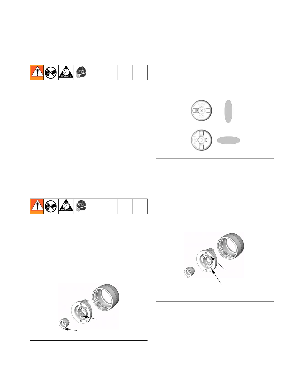
Install a Spray Tip
Position the Air Cap
The air cap and spray tip position determines the direction of the spray pattern.
Rotate the air cap (the spray tip rotates with it) as
needed to achieve the desired spray pattern direction.
See F
IG. 8.
TI6558A
F
IG. 8
Air Cap Alignment Pin
Air caps are factory-set with an air cap alignment pin to
position the air cap. The standard location of the air cap
alignment pin is the vertical spray pattern.
1. Perform Pressure Relief Procedure, page 12.
2. Install a spray tip in the gun.
3. Align tip locating tab with slot on the air cap. See
F
IG. 7.
4. Tighten the air cap retaining ring (8) firmly by hand
to ensure a good seal between the tip gasket and
the diffuser (10).
Slot
Tip Locating Tab
FIG. 7
TI6847A
To change the spray pattern direction, use a needle
nose pliers to unscrew the pin and relocate it to the
desired position. See F
use low-strength thread locker. Torque to 1.5-2.5 in-lb
(0.2-0.3 N•m). Do not overtighten.
IG. 9
F
IG. 9. When relocating the pin
Horizontal
Air Cap Position
(standard)
Verti cal
Air Cap Position
TI6847A
311052E 11
Page 12
Operation
Operation
Pressure Relief Procedure
1. Turn off the air and fluid supply to the gun.
2. Close the bleed-type master air valve (required in
the system).
3. Trigger the gun into a grounded metal waste container to relieve the fluid pressure.
TI8174a
Adjust Spray Pattern
The air-assisted spray gun combines airless and air
spray concepts. The spray tip shapes the fluid into a fan
pattern, as does a conventional airless spray tip. Air
from the air cap further atomizes the fluid and completes
the atomization of the paint tails into the pattern to produce a more uniform pattern.
The fan air can be used if necessary to slightly adjust
the pattern size.
Air-assisted spray guns differ from air spray guns in
that increasing the fan air reduces the pattern
width. To increase the pattern width, use less fan
air or a larger size tip.
1. Set the fluid pressure at 300 psi (2.1 MPa, 21 bar)
with the fluid regulator.
FIG. 10: Pressure Relief
4. Open the pump drain valve (required in the system)
to relieve fluid pressure in the displacement pump.
In addition, open the drain valve connected to the
fluid pressure gauge (in a system with fluid regulation) to relieve fluid pressure in the hose and gun.
Have a container ready to catch the drainage.
5. Leave the drain valve(s) open until you are ready to
spray again.
6. If you suspect that the spray tip or hose is completely clogged or that pressure has not been fully
relieved, very slowly loosen the hose end coupling
and relieve pressure gradually, then loosen the coupling completely. Clear the tip or hose obstruction.
For a narrower pattern, supply air to the gun fan air inlet
(or open the fan adjustment valve on manifold 288223).
The tip size is the primary controller of the pattern size.
Use the fan air only as needed to slightly adjust the pattern size.
2. Trigger the gun to check the atomization; do not be
concerned about the pattern shape yet.
3. Slowly Increase the fluid pressure just to the point
where a further increase in fluid pressure does not
significantly improve fluid atomization.
4. Turn on the atomizing air and set the air pressure at
about 10 psi (70 kPa, 0.7 bar). Check the spray pattern, and then adjust the air pressure until the tails
are completely atomized and pulled into the spray
pattern. See F
MPa, 7 bar) air pressure to the gun.
For HVLP operation do not exceed 10 psi at the air
cap. Use HVLP verification kit 249140 to measure
the atomization pressure at the air cap.
IG. 11. Do not exceed 100 psi (0.7
12 311052E
Page 13

TI0792
no air
too little air correct amount
of air
IG. 11: Correct Spray Pattern
F
Apply Fluid
The spray gun has a built-in lead and lag operation.
When triggered, the gun begins emitting air before the
fluid is discharged. When the trigger actuation air is
stopped, the fluid stops before the air flow stops. This
helps assure the spray is atomized and prevents fluid
buildup on the air cap and tip.
Adjust the system control device, if it is automatic, so the
gun starts spraying just before meeting the work piece
and stops as soon as the work piece has passed. Keep
the gun a consistent distance, 8 to 10 inches (200 to 250
mm), from the surface of the object being sprayed.
Operation
To achieve best results when applying fluid:
• Keep gun perpendicular and 8 to 10 inches (200 to
250mm) from object being sprayed.
• Use smooth, parallel strokes across surface to be
sprayed with 50% overlap. See F
IG. 12.
Incorrect
TI8098a
Correct
TI8099a
FIG. 12: Correct Spray Method
311052E 13
Page 14

Maintenance
Maintenance
Daily Gun Care CAUTION
Methylene chloride with formic or propionic acid is not
recommended as a flushing or cleaning solvent with
this gun as it will damage aluminum and nylon components.
CAUTION
Solvent left in gun air passages could result in a poor quality paint finish. Do not use any cleaning method which
may allow solvent into the gun air passages.
Do not point the gun up while cleaning it.
Do not wipe the gun with a cloth soaked in solvent;
ring out the excess.
TI8100a
Do not immerse the gun in solvent.
TI8101a
TI4827a
Do not use metal tools to clean the air cap holes as
this may scratch them; scratches can distort the spray
pattern.
TI6565a
14 311052E
Page 15

Maintenance
General System Maintenance
1. Perform Pressure Relief Procedure, page 12.
2. Clean the fluid and air line filters daily.
3. Check for any fluid leakage from the gun and fluid
hoses. Tighten fittings or replace equipment as
needed.
4. Flush the gun before changing colors and whenever
you are done operating the gun.
Flushing and Cleaning
To reduce the risk of serious injury, including splashing fluid in the eyes or on the skin, or static electric
discharge when flushing:
• Ensure that the entire system, including flushing
pails, are properly grounded.
• Remove the spray tip.
• Maintain metal to metal contact between the gun
and the flushing pail.
• Use the lowest possible pressure.
1. Perform Pressure Relief Procedure, page 12.
2. Shut off the gun fan and atomizing air.
3. Remove the air cap retaining ring (8), air cap (30),
and spray tip (9).
4. Disconnect the fluid supply hose and air supply
hose from the gun.
5. Connect the solvent supply hose to the gun.
6. Increase the pressure slowly. Point the gun down
into a grounded metal container, and flush the gun
with solvent until all traces of fluid are removed from
the gun passages.
TI8174a
FIG. 13
CAUTION
This gun is not adjustable. To ensure proper shutoff,
screw the piston cap (27) onto the housing (1) until it
bottoms out.
• Flush before changing colors, before fluid can
dry in the equipment, at the end of the day,
before storing, and before repairing equipment.
• Flush at the lowest pressure possible. Check
connectors for leaks and tighten as necessary.
• Flush with a fluid that is compatible with the
fluid being dispensed and the equipment wetted
parts.
• If it is available, the flushing procedure provided
in the pump or sprayer manual should be used
instead of this procedure.
• Clean the front of the tip frequently during the
day to reduce buildup.
311052E 15
Page 16

Maintenance
7. Turn off the solvent supply.
8. Perform Pressure Relief Procedure, page 12.
9. Disconnect the solvent supply hose from the gun.
10. Dip the end of a soft-bristle brush into a compatible
solvent. Do not continuously soak the brush's bris-
tles with solvent and do not use a wire brush.
TI4845A
F
IG. 14
11. With the gun pointed down, clean the front of the
gun, using the soft-bristle brush and solvent.
12. Scrub the air cap retaining ring (8), air cap (30), and
spray tip (9) with the soft-bristle brush. To clean out
air cap holes, use a soft tool, such as a toothpick, to
avoid damaging critical surfaces. Blow air through
the spray tip to ensure the orifice is clean. Clean the
air cap and spray tip daily, minimum. Some applica-
tions require more frequent cleaning.
TI6570A
FIG. 15
13. Install the air cap retaining ring (8), air cap (30), and
spray tip (9).
14. Dampen a soft cloth with solvent and wring-out the
excess. Point the gun down and wipe off the outside
of the gun.
16 311052E
Page 17

Troubleshooting
Troubleshooting
Check all possible remedies in the troubleshooting
charts before disassembling the gun.
Some improper patterns are caused by the
improper balance between air and fluid. Refer to
Spray Pattern Troubleshooting, page 19.
General Troubleshooting
Problem Cause Solution
Fluid leakage through venting holes. Worn packings or needle. Replace needle assembly. (14)
Air leakage through venting hole. Worn o-ring (23) or gasket (15). Check and replace parts as needed.
Air leakage from back of gun. Worn o-rings (22, 23). Replace o-rings.
Air does not trigger. Piston stem is disconnected from
main body of piston assembly (20).
Air does not shut off. Piston assembly not seating properly.
Replace piston assembly.
Clean/service piston assembly.
Replace worn or swollen o-rings.
Broken return spring (29).
Swollen o-ring (22).
Worn piston stem o-rings (25, 26).
Bottom gasket (16) failed.
Fluid leakage from front of gun. Fluid needle (14) dirty, worn, or dam-
aged.
Dirty or worn diffuser-seat (10).
Fluid is present at air cap holes. Spray tip is leaking,
Diffuser-seat (10) is insufficiently
tightened.
Replace spring.
Replace o-rings.
Replace o-rings.
Replace gasket.
Clean or replace fluid needle.
Clean or replace diffuser-seat.
To improve sealing while spraying
lightweight materials and sealing life
while spraying acid catalyzed materials, use optional SST ball and plastic
seat.
Verify that retainer (8) or RAC air cap
assembly (30), are tight. If so, replace
spray tip (9).
Tighten diffuser-seat.
311052E 17
Page 18

Troubleshooting
Problem Cause Solution
Fluid needle will not trigger. Loose or missing fluid needle stop
(21) or setscrew (19).
Replace stop or tighten setscrew.
Broken fluid needle (14).
Air leaking around piston (20).
Swollen piston o-ring (22).
Insufficient air pressure on trigger.
Spray tip (9) is plugged.
Fluid filter is plugged.
Plug (5) is in incorrect fluid port.
Fluid does not shut off. Worn o-ring (25).
Piston cap (27) not fully tightened.
Spring (28) not in place.
Replace fluid needle.
Replace o-ring (22) or piston assembly (20).
Replace o-ring. Do not immerse piston in solvent.
Increase air pressure or clean air
line.
Clean spray tip and air cap (30).
Clean or replace filter.
Move plug to fluid port consistent with
manifold plumbing, unless you are
using gun in a circulating system. If
you are, all fluid ports in gun and on
manifold should be open.
Replace o-ring.
Tighten piston cap until it bottoms
out.
Check spring position.
Swollen piston o-ring (22).
Replace o-ring. Do not immerse piston in solvent
18 311052E
Page 19

Spray Pattern Troubleshooting
Problem Cause Solution
Fluttering spray. Insufficient fluid supply.
Troubleshooting
Adjust fluid regulator or fill fluid supply tank.
Air in paint supply line.
Spitting spray. Worn diffuser-seat (10) or needle
(14) ball.
Dirty spray tip (9) or air cap (30).
Irregular pattern. Fluid build-up or spray tip partially
plugged.
On defective side of pattern, air horn
holes are partially or totally plugged.
Pattern pushed to one side, same
side of air cap gets dirty.
Air horn holes partially or totally
plugged.
Check, tighten siphon hose connections, bleed air from paint line.
Inspect diffuser-seat and needle for
wear. Replace if necessary.
To improve sealing when spraying
lightweight materials and sealing life
when spraying acid catalyzed materials, use needle (SST) available with
1/8 in. ball only, and diffuser-seat
(plastic). See Parts, page 25.
Clean.
Clean spray tip. See page 15.
Clean air horn holes with solvent and
soft brush. See page 15.
Clean air horn holes with solvent and
soft brush. See page 15.
311052E 19
Page 20

Service
Service
Follow the Service Notes in FIG. 17 and FIG. 18
when reassembling the gun.
Gun repair kits are available. See page 34. Reference numbers marked with an asterisk (*) in the
service procedures are included with the 288171
Air Seal Repair Kit. Reference numbers marked
with a symbol (†) in the service procedures are
included with the 288136 Fluid Repair Kit.
4. Inspect the tip seal (9a) in place. If damaged,
replace the tip seal.
5. Remove the cap (27) from the piston housing (1).
Remove the springs (28 and 29).
6. Using the supplied wrench (38), loosen the fluid
needle setscrew (19). Remove the needle stop (21).
7. Trigger the gun (or remove cap (27) and springs (28,
29)) to pull the needle housing off the seat while you
unscrew the diffuser (10) from the gun body (1).
Items Needed for Service
• 1/16 in. Hex Wrench - provided
•3 mm Hex Wrench
• Adjustable Wrench
•4 mm Hex Wrench
• 5/16 in. Nut Driver
• Pliers
• Lubricant part no. 111265; see Accessories, page
34, to order
• Compatible Solvent
Disassembly
1. Perform Pressure Relief Procedure, page 12.
2. Unscrew the four screws (17) and remove the gun
from the manifold.
3. Unscrew the air cap retainer (8). Remove the air cap
(30) and spray tip (9). See F
IG. 17.
8. Unscrew the needle assembly (14) and use 5/16 in.
nut driver to pull the assembly straight out the front
of the gun.
CAUTION
Be sure to keep the needle straight when removing it
from the gun. If the needle is bent, it must be
replaced.
9. Remove the piston. Using a pliers, pull the piston
(20) out of the piston housing (1). See F
IG. 16.
Model 288053: Unscrew the air cap (30). Remove
the RAC spray tip (9) and RAC housing (11). See
Parts, page 25.
20 311052E
Page 21

10. If gasket (15) needs to be replaced, unscrew the two
screws (18) and separate the fluid housing (2) and
piston housing (1). Inspect gasket (16) and replace
if needed.
Gasket (16) is attached to assembly with adhesive;
therefore, if you are replacing gasket (16), ensure
that a replacement gasket is available.
18
2
18
Service
1
TI8173b
F
IG. 16
11. Remove the large o-ring (22) from the piston and
the smaller o-ring (23) from the piston shaft.
Remove the two o-rings (25, 26) from each of the
piston stems. Check that the stems are solidly in
place. If they are loose, replace the entire piston
assembly (20).
12. Perform the following applicable step:
a. Non-circulating guns: Remove the fluid outlet
port plug (5) and gasket (4) from the fluid housing (2). Remove the o-ring (6) and backup o-ring
(7) from the plug.
b. Circulating guns: Remove the gasket (4) from
the fluid housing (2).
13. Clean all parts and replace any worn parts. When
assembling, lubricate the threads with anti-seize
lubricant.
311052E 21
Page 22

Service
8
30
9a
10e
10a
4
27
8
22*
2
1
3
2
2
2
5
26*
15*
25*
3
29
28
21
19
6
7
FIG. 17
9
10
2
10d
10f
Cutaway View:
Part No. 288044 Gun Shown
20
23*
3
14
2
1
4†
16*
TI8123a
SERVICE NOTES:
Lubricate threads with anti-seize lubricant
2
3
Lubricate with light-weight oil
4
Do not lubricate
Torque to 155-165 in-lb (18-19 N•m)
5
Apply semi-permanent anaerobic sealant
6
Torque to 4-5 in-lb (0.45-0.56 N•m)
7
Tighten cap (27) until it bottoms out
8
22 311052E
Page 23

Service
Diffuser Seat Replacement
•See Accessories, page 34.
• Clean parts with a solvent that is compatible
with the parts and the fluid being sprayed.
1. Perform Pressure Relief Procedure, page 12.
2. Remove gun from manifold.
3. Remove the air cap retaining ring (8), air cap (30),
and spray tip (9).
4. Trigger the gun (or remove cap (27) and springs (28,
29)) to pull the needle housing off the seat while you
unscrew the diffuser (10) from the gun body (1).
5. Inspect the o-rings (10d, 10e, 10f) in place. Carefully remove the o-rings from the diffuser housing
(10) and replace if necessary.
6. Remove the seat nut (10c), seat (10b) and seat gasket (10g) (Carbide seat only) using a 7/32 in. hex
wrench.
7. Inspect the seat (10b) and seat gasket (10g) and
replace if necessary.
8. Reinstall the seat gasket (10g) (Carbide seat only),
seat (10b), and seat nut (10c). Torque to 45-50 in-lb
(5.1-5.7 N•m). Be sure not to overtighten the nut.
When reinstalling the carbide seat, the tapered end
of the seat (red side) must point toward the gun tip.
4. Align the gasket (15*) as shown in the exploded
view in Fig. 8.
If replacing gasket (15), place the gasket on the piston housing (1), then install the fluid housing (2).
Torque the two screws (18) to 30 in-lb (3.4 N•m)
5. Insert the piston (20) into the piston housing (1).
6. Remove the protective paper from the sticky side of
the gasket (16*) and adhere the gasket to the bottom of the piston housing (1), making sure the three
holes in the gasket are properly aligned with the
matching holes in the housing.
CAUTION
Be sure to keep the needle straight when installing it
in the piston housing. If the needle is bent it must be
replaced.
7. Insert the needle assembly (14) into the front of the
fluid housing (2). Tighten to 50-60 in-lb (5.7-6.8
N•m).
8. Lubricate the threads of the diffuser-seat (10).
Screw it into the fluid housing (2) and torque to 65
in-lb (7.3 N•m).
9. Install the needle stop (21) on the needle. Coat the
setscrew (19) with semi-permanent anaerobic sealant and install the screw into the needle stop.
Torque to 4-5 in-lb (0.45-0.56 N•m). Pull on the needle to make sure it seats fully.
10. Install the springs (28, 29).
The plastic seat, standard in Model 288044, can be
reinstalled in either direction. However, do not
reverse the direction of the seat if it is worn; it must
be replaced.
Reassembly
1. Non-circulating guns only: Lubricate the backup
o-ring (7†) and o-ring (6†) and install them on the
fluid outlet port plug (5). Install the plug in the fluid
outlet port of the fluid housing (2). See F
2. All guns: Reinstall the gasket (4) in the fluid housing
(2).
3. Install the o-rings (22*, 23*) on the piston (20).
Install two o-rings (25*, 26*) on each of the piston
stems. Lubricate all the o-rings, the piston, and the
piston stems.
311052E 23
IG. 18.
11. Lubricate the threads of the piston housing (1).
Screw the cap (27) onto the housing until it bottoms
out.
12. Model 288053: Install the RAC housing (11) and
RAC spray tip (9) in the RAC air cap assembly (30).
Position the blue tip guard as desired and screw the
air cap assembly onto the gun until it bottoms out.
See Parts, page 25.
Assemble the standard tip and air cap.
13. Reinstall the gun on the manifold with the four
screws (17). Torque to 65 in-lb (7.3 N•m).
Page 24

Parts
Parts
30
10d†
9
4
10a
10g✓✿
2
5
10b✓
10c✓
14
2
2
15*
17
3
44
2
5
9
6†
7†
9
3
9
8
27
29
43
42
8
8
2
1
AA RAC Assembly included with
Model 288053 only
9a
11
17
16*
10e†✿
10a
10f†✿
18
4†
23*
28
6
22*
19
3
7
21
20
25*
3
26*
3
3
14 (ref)
SERVICE NOTES:
Lubricate threads with anti-seize lubricant
2
3
Lubricate with light-weight oil
4
Do not lubricate
Torque to 65 in-lb (7.3 N•m)
5
6
Apply semi-permanent anaerobic sealant
7
Torque to 4-5 in-lb (0.45-0.56 N•m)
8
Tighten cap (27) until it bottoms out
9
Used on non-circulating guns only
TI8088b
46
9
TI8228a
FIG. 18
24 311052E
Page 25

Parts
Parts
Part
Ref. No.
1BODY 1
2 HOUSING, fluid, SST 1
4 288200 GASKET, fluid, plastic
5 192687 PLUG, fluid, internal, SST 1
6 114244 PACKING, o-ring,
7 114340 RING, back-up, PTFE
8◆❖ 249134 RING, retaining, assy 1
8a 109213 O-RING, PTFE (see Kit
9 TIP, includes 9a,
10 DIFFUSER, assy 1
10a DIFFUSER, housing 1
10b ✓ SEAT 1
10c✓ NUT, seat 1
10d† 111116 PACKING, o-ring, seat; PTFE 1
10e†✿ 109450 PACKING, o-ring; PTFE 1
10f†✿ 111457 PACKING, o-ring; PTFE 1
10g✓✿ 15F409 GASKET, seat (Diffuser assy
11★ 15J770 HOUSING, RAC 1
14 NEEDLE, assy 1
15* 15H316 GASKET, polyethylene (front) 1
No. Description Qty.
homopolymer, pack of 10
fluoroelastomer
253032, p. 35, for pack of 5)
see tip selection charts,
page 29
AAPxxx Model 288044
LTXxxx Model 288053, includes 9a
249132 with plastic seat
Model 288044
288192 with Carbide seat
Models 288046, 288053
249877 with RAC seat
Model 288053
with carbide seat only)
288190 SST ball
Model 288044
288191 Carbide ball
Models 288046, 288053
Ref. No.
16* 114134 GASKET, polyethylene (bottom) 1
17 15H317 SCREW, mounting manifold
2
18 15H318 SCREW, SHCS 4
19 114137 SCREW, set; 6-32, 1/8 in. long 1
20 240895 PISTON, assy 1
1
21 192452 STOP, needle, SST 1
22* 115066 PACKING, o-ring,
23* 111450 PACKING, o-ring,
1
25* 112319 PACKING, o-ring,
1
26* 111504 PACKING, o-ring,
27 192453 CAP, piston 1
28 114138 SPRING, compression 1
29 114139 SPRING, compression 1
30◆❖ 288194 CAP, air, assy 1
38 114141 WRENCH, hex (not shown) 1
42◆❖ 15G320 WASHER, PTFE, 1.2 in. O.D.
43
◆❖ 15G618 PIN, locating, threaded 1
44 15H702 INSERT, plastic 1
46★ 249478 GUARD, RAC, G40 1
◆ Model 288044 only.
❖ Model 288046 only.
1
★ Model 288053 only.
† Included in Fluid Seal Repair Kit 288136.
* Included in Air Seal Repair Kit 288171.
✓ Included in Seat Repair Kits 249424 (plastic) or
✿ Part not for sale.
Part
No. Description Qty.
249456 (carbide).
4
(M5)
1
fluoroelastomer
1
fluoroelastomer
2
fluoroelastomer
2
fluoroelastomer
1
(see Kit 253032, p. 35, for pack
of 5)
311052E 25
Page 26

Parts
Part No. 288217
North America Manifold with side fluid ports
Part No. 288218
International Manifold with side fluid ports
Ref.
No. Part No. Description Qty.
101 MANIFOLD, side fluid ports 1
103 1
120388❖ FITTING, tube, air inlet;
1/4 in. OD tube x 1/8 npt(m)
120538◆ FITTING, tube, air inlet;
6 mm OD tube x 1/8 npt(m)
105 114246 SCREW, set; 5/16;0.437 in. long 1
107 2
114342❖ ELBOW, street, 1/4 in. npt
114247◆ FITTING, elbow, male;
#5 JIC x 1/4 npt
108 2
120389❖ FITTING, tube, air line;
3/8 in.OD tube x 1/4 npt
120537◆ FITTING, tube, air line;
8 mm OD tube x 1/4 npt
109❄ 101970 PLUG, pipe, SST; 1/4-18 ptf, sup-
plied to plug fluid outlet port in
non-circulating applications
114 120453 SCREW, SCHS, M3 x 18 1
❄ Not shown.
2
Apply anti-seize lubricant (222955) to threads and mating faces
of manifold (101) and any fittings and/or plugs used in fluid
ports.
101
114
2
103
3
107
F
IG. 19: North America and International Manifold
105
107
108
TI8148b
❖ Part No. 288217 only.
◆ Part No. 288218 only.
26 311052E
Page 27

Part No. 288221
Manifold with bottom fluid ports
Ref.
No. Part No. Description Qty.
101 MANIFOLD, bottom fluid ports 1
103 120388 FITTING, tube, air inlet;
1/4 in. OD tube x 1/8 npt(m)
105 114246 SCREW, set; 5/16;0.437 in. long 1
107 166846 NIPPLE, SST; 1/4 npsm, straight
pipe thread x 1/4 npt
108 120389 FITTING, tube, air line;
3/8 in.OD tube x 1/4 npt
109❄ 101970 PLUG, pipe, SST; 1/4-18 ptf, sup-
plied to plug fluid outlet port in
non-circulating applications
114 120453 SCREW, SCHS, M3 x 18 1
❄ Not shown.
Parts
2
Apply anti-seize lubricant (222955) to threads and mating faces
of manifold (101) and any fittings and/or plugs used in fluid
ports.
1
114
101
2
2
103
1
2
107
105
F
IG. 20: Manifold with Bottom Fluid Ports
108
TI9398b
311052E 27
Page 28

Parts
Part No. 288224
High Pressure Air-Assisted Manifold with side fluid ports
and fan adjustment valve
Part No. 24C343
International Manifold with side fluid ports
2
Apply anti-seize lubricant (222955) to threads and mating faces
of manifold (101) and any fittings and/or plugs used in fluid
ports.
3
Install with valve turned fully counterclockwise to outermost
position.
Ref.
No. Part No. Description Qty.
101 ---- MANIFOLD, fan adjustable 1
102 244029 VALVE, fan, assy. 1
103
120388❖
120538◆
104
120389❖
120537◆
15D916◆❄
FITTING, tube, air inlet
1/4 in. OD tube x 1/8 npt(m)
6 mm OD tube x 1/8 npt(m)
FITTING, tube, air line
3/8 in.OD tube x 1/4 npt
8 mm OD tube x 1/4 npt
4 mm OD tube x 1/4 npt;
shipped loose
107 114246 SCREW, set; 5/16;0.437 in. long 1
108
114342❖
114247◆
ELBOW, male
1/4 - 18 npt
#5 JIC x 1/4-18 npt
109❄ 101970 PLUG, pipe, SST; 1/4-18 ptf,
supplied to plug fluid outlet port
in non-circulating applications
114 120453 SCREW, SCHS, M3 x 18 1
❄ Not shown, optional size.
---- Not sold separately.
❖ Part No. 288224 only.
4
Torque to 125-135 in-lb (14-15 N•m).
108
114
1
1
108
2
104
2
1
3
102
4
F
IG. 21: Side Fluid Ports and Fan Adjustment Valve
107
101
103
TI0556b
◆ Part No. 24C343 only.
28 311052E
Page 29

Part No. 288160
Rear Port Manifold, North America
Part No. 288211
Rear Port Manifold, International
1
Apply sealant to threads and mating faces of manifold (101) and
any fittings and/or plugs used in fluid ports.
2
Torque to 30-42 in-lb (3.4-4.7 N•m).
Parts
Ref.
No. Part No. Description Qty.
101 MANIFOLD, aluminum 1
103 FITTING, fluid path 2
15H521❖ 1/4 npsm
15J003◆ #5 JIC
105 116475 SCREW, SHCS, M4 x 12 2
106 120353 O-RING, PTFE 2
107 15J077 O-RING, PTFE 2
110 114246 SCREW, set, hex soc 1
111 2
120389❖ FITTING, tube, air line;
3/8 in.OD tube x 1/4 npt
120537◆ FITTING, tube, air line;
8 mm OD tube x 1/4 npt
112 1
120388❖ FITTING, tube, air inlet;
1/4 in. OD tube x 1/8 npt(m)
120538◆ FITTING, tube, air inlet;
6 mm OD tube x 1/8 npt(m)
113 103253 SCREW, set 2
❖ Part No. 288160 only.
◆ Part No. 288211 only.
3
Torque to 110-130 in-lb (12.3- 14.7 N•m).
105
102
101
1
110
2
F
IG. 22:
113
107
106
103
112
111
1
3
1
1
TI8200a
311052E 29
Page 30

Notes
Notes
30 311052E
Page 31

AAP Series Tip and Air Cap Selection Charts
AAP Series Tip and Air Cap Selection Charts
AAP Series Precision Spray Tips .
Order desired tip (Part No. AAPxxx) where xxx is
the size code for the chart.
Tips are physically marked with Xxxx, where xxx is
the size code from the chart.
Maximum Pattern Width at 12 in. (300mm)
* Fluid Output, fl oz/min (lpm)
Orifice Size in.
(mm)
† 0.009 (0.229) 7.0 (0.2) 9.1 (0.27) 209 309 409 509
† 0.011 (0.279) 10.0 (0.3) 13.0 (0.4) 211 311 411 511 611
0.013 (0.330) 13.0 (0.4) 16.9 (0.5) 213 313 413 513 613 713
0.015 (0.381) 17.0 (0.5) 22.0 (0.7) 215 315 415 515 615 715 815
0.017 (0.432) 22.0 (0.7) 28.5 (0.85) 317 417 517 617 717 817
0.019 (0.483) 28.0 (0.8) 36.3 (1.09) 419 519 619 719
0.021 (0.533) 35.0 (1.0) 45.4 (1.36) 421 521 621
at 600 psi
(4.1 MPa, 41 bar)
at 1000 psi
(7.0 MPa, 70 bar)5(127)
Pattern Width Tolerance +/- 0.5 in. (13.0 mm)
7
(178)
9
(228)
11
(279)
13
(330)15(381)
17
(432)
* Tips are tested in water.
† Tip sizes include a 150 mesh tip filter
Fluid output (Q) at other pressures (P) can be calculated by this formula: Q = (0.041) (QT)
where QT = fluid output (fl oz/min) from the above table for 600 psi.
Air Cap
Typical Air
Application Tip Used With
Standard All AAP, GG4,
GG5, and AAM
Series
Consumption Part No.
3-6 scfm 288194
P
311052E 31
Page 32

LTX Series RAC Tip Selection Charts
LTX Series RAC Tip Selection Charts
For use with G40 RAC Housing
* Fluid Output, fl oz/min
(lpm)
at 2000 psi
Orifice Size in. (mm)
0.009 (0.229) 11.2 (0.33) 209 309
0.011 (0.279) 16.6 (0.49) 211 311 411 511
0.013 (0.330) 23.3 (0.69) 213 313 413 513
0.015 (0.381) 30.8 (0.91) 215 315 415 515 615
0.017 (0.432) 39.5 (1.17) 217 317 417 517 617
0.019 (0.483) 49.7 (1.47) 219 319 419 519 619
0.021 (0.533) 60.5 (1.79) 321 421 521 621
0.023 (0.584) 72.7 (2.15) 423 523 623
0.025 (0.635) 85.9 (2.54) 525 625
0.027 (0.686) 100.0 (2.96) 527 627
0.029 (0.737) 115.6 (3.42) 629
0.031 (0.787) 131.8 (3.90) 531 631
(14.0 MPa, 140 bar)
4 to 6
(150)
✖ Maximum Pattern Width at 12 in. (300 mm)
6 to 8
(200)
8 to 10
(250)
10 to 12
(300)
* Tips are tested in water.
✖ Pattern width measured without airflow.
LTX Reverse-A-Clean (RAC) Spray Tips
12 to 14
(350)
• LTX RAC spray tips include a metal fluid seat and rubber fluid seal.
• G40 RAC conversion kits are available. See page 32.
Housing
G40 RAC Tip
Guard/Air Cap Assy.
* Tip Cylinder
FIG. 23
* Included with the LTX RAC spray tip.
† Optional acetal fluid seal 248936 (pack of 5) available.
*†Fluid
Seal
* Fluid
Seat
TI8125a
32 311052E
Page 33

LTX Series RAC Tip Selection Charts
RAC Switch Tips
FFT Fine Finish RAC Spray Tips
Order desired tip (Part No. FFTxxx) where xxx is
the size code for the chart.
* Fluid Output, fl oz/min (lpm) ❖ Maximum Pattern Width at 12 in. (305 mm)
Orifice Size in.
(mm)
0.008 (0.203) 8.8 (0.26) 208 308
0.010 (0.254) 13.9 (0.41) 210 310 410 510
0.012 (0.305) 19.9 (0.59) 212 312 412 512 612
0.014 (0.356) 27.0 (0.80) 214 314 414 514 614
WRX Wide RAC Spray Tips
at 2000 psi
(14.0 MPa, 140 bar)
4 to 6
(150)
6 to 8
(200)
8 to 10
(250)
10 to 12
(300)
12 to 14
(350)
Order desired tip (Part No. WRXxxx) where xxx is
the size code for the chart.
* Fluid Output,
fl oz/min (lpm)
Orifice Size in.
(mm)
0.021 (0.533) 60.5 (1.79) 1221
0.023 (0.584) 72.7 (2.15) 1223
0.025 (0.635) 85.9 (2.54) 1225
0.027 (0.686) 100.0 (2.96) 1227
0.029 (0.737) 115.6 (3.42) 1229
0.031 (0.787) 131.8 (3.90) 1231
0.033 (0.838) 149.4 (4.42) 1233
0.035 (0.889) 168.3 (4.98) 1235
0.037 (0.940) 187.9 (5.56) 1237
0.039 (0.991) 208.9 (6.18) 1239
at 2000 psi
(14.0 MPa, 140 bar)
Pattern Width at
* Tips are tested in water.
❖ Maximum
12 in. (305 mm)
24 in.
(610)
❖ Measured with NO airflow. Air assist will tend to reduce pattern lengths by 1 in. to 2 in.
311052E 33
Page 34

Accessories
Accessories
Gun Manifolds
Order separately; not included with gun
(See Parts, page 25)
Part No. 288217
North America Manifold with side fluid ports
Part No. 288218
International Manifold with side fluid ports
Part No. 288221
Manifold with bottom fluid ports
Part No. 288224
High Pressure Air Assisted Manifold with side fluid ports
and manual fan adjustment valve
Part No. 24C343
High Pressure Air Assisted Manifold, International
Part No. 288160
Rear port manifold, North America
Part No. 288211
Rear port manifold, International
Needle/Diffuser Options
Needles must be used only with the specified diffuser-seat to guarantee proper seating and life.
• Standard viscosity/standard flow
Lacquer Air Cap Kit 289080
Kit includes air cap for optimized spray of lacquer materials.
RAC Gasket 246453
Pack of five standard replacement RAC gaskets.
Acetal RAC Gasket 248936
Pack of five plastic (acetal) replacement RAC gaskets.
Gasket Filter 288201
Optional 100 mesh filter that can be installed in the fluid
inlet gasket (4) for added filtration. Pack of ten.
RAC Conversion Kit 287917
To convert from a gun with standard spray tip, tip guard,
and air cap to Part No. 288053 gun with the AA RAC
assembly. See parts list and drawing below for parts
included with kit.
Ref.
No. Part No. Description Qty.
1 249478 CAP, air, AA RAC, assy 1
2 15J770 HOUSING, RAC 1
3 LTXxxx TIP, cylinder; tip of choice; includes
item 3a
3a SEAT, fluid 1
4 249877 SEAT, diffuser 1
2
• Fluid Needle 288191, carbide ball
• Diffuser-Seat 288192, carbide seat
4
• Acid catalyzed materials/very low viscosity
materials
• Fluid Needle 288190, SST ball
• Diffuser-Seat 288193, plastic seat
1
3a
2
3
HVLP Air Cap Verification Kit 249140
Use to determine air pressure behind the air cap. Do not
use for actual spraying.
To be HVLP compliant, the atomizing air pressure
must not exceed 10 psi (70 kPa, 0.7 bar).
34 311052E
Tip (3) is not included with kit; order separately. See
LTX Series RAC Tip Selection Charts, page 32.
TI8126a
Page 35

Accessories
Air Cap Seal Kit 253032
Pack of five seals and five o-rings for the air cap
assembly.
Plastic Seat Repair Kit 249424
Kit includes replacement plastic seat (pack of ten), and
seat nut.
SST Seat Repair Kit 287962
Kit includes assembled diffuser with SST seat (15H282)
for use with pigmented acid catalyzed materials.
Carbide Seat Repair Kit 249456
Kit includes replacement carbide seat, seat gasket, and
seat nut.
Tip Filter Kit 241804
Replacement filters (pack of ten) for spray tip orifice
sizes 0.007, 0.009, and 0.011.
Grounding Clamp and Wire 222011
Bleed-type Master Air Valve
300 psi (2.1 MPa, 21 bar) Maximum Working Pressure
Relieves air trapped in the air line between the pump air
inlet and this valve when closed.
Part No. Description
107141 3/4 npt(m x f) inlet and outlet
107142 1/2 npt(m x f) inlet and outlet
Ultimate Gun Cleaning Kit 15C161
Kit includes brushes and tools for gun maintenance.
Unclogging Needle 249598
Kit includes picks for unclogging gun tip.
Brush 101892
For cleaning the gun.
Retrofit Adapter Plate 288197
The retrofit adapter plate enables the manifold to be
attached to a variety of bolt patterns.
In-line Fluid Filter 210500
5000 psi (35 MPa, 350 bar) Maximum Working Pressure
100 mesh. Fits onto the gun's fluid connector. 1/4-18
npsm. Includes the parts shown below.
168517
Filter
164075
}
210501
205264
High Pressure Ball Valves, Fluoroelastomer
Seals
5000 psi (34 MPa, 345 bar) Maximum Working Pressure
Can be used as fluid drain valve.
• 210657 1/2 npt(m)
• 210658 3/8 npt(m)
• 210659 3/8 x 1/4 npt(m)
311052E 35
Page 36
Dimensions
Dimensions
2.0 in. (50.8 mm)
3.0 in.
(76.2 mm)
TI8113a
3.86 in. (98.0 m)
4.9 in. (124.5 mm)
1.375 in.
(34.9 mm)
2.0 in.
(50.8 mm)
2.40 in.
(60.96 mm)
TI8127a
FIG. 24
36 311052E
Page 37

Mounting Hole Layout
Mounting Hole Layout
0.5 in. (12.7 mm)
0.805 in. (20.5 mm)
0.187 in. (4.8 mm)
Remove set screws
when using bottom
mounting pattern.
2.125 in.
(54 mm)
0.4 in. (10.2 mm)
1.375 in.
(35 mm)
TI8127a
Two M5 x 0.8 x 0.25 in.
(6.3 mm) holes
1.750 in.
(44.5 mm)
Two 0.128 diameter x
0.31 in. (7.8 mm) deep
holes (for alignment pin)
TI8107a
FIG. 25:
311052E 37
Page 38

Mounting Hole Layout
Mounting Hole Layout
Rear Port Manifold
Gun with Rear Port
Manifold
(81.28 mm)
3.200 in.
0.875 in.
(22.23 mm)
0.205 in.
(5.21 mm)
1.010 in.
(25.65 mm)
1.375 in.
(34.93 mm)
0.400 in.
(10.16 mm)
0.375 in. (9.53 mm)
1.765 in.
(44.83 mm)
TI8226a
2.325 in.
(59.06 mm)
Retrofit Adapter Plate
2.007 in.
(50.98 mm)
1.375 in.
(34.93 mm)
FIG. 26: Mounting Hole Layouts
3.720 in.
(94.49 mm)
0.736 in.
(18.69 mm)
TI8178a
2.400 in.
(60.96 mm)
Gun with Retrofit
Adapter Plate
TI8231a
2.250 in.
(57.15 mm)
TI8227a
38 311052E
Page 39

Technical Data
Technical Data
Maximum Working Fluid Pressure . . . . . . . . . . . . . . . . . . 4000 psi (28 MPa, 280 bar)
Maximum Working Air Pressure . . . . . . . . . . . . . . . . . . . . 100 psi (0.7 MPa, 7 bar)
Maximum Working Fluid Temperature . . . . . . . . . . . . . . . 120° F (49° C)
Minimum Air Cylinder Actuation Pressure . . . . . . . . . . . . 50 psi (0.34 MPa, 3.4 bar)
Weight . . . . . . . . . . . . . . . . . . . . . . . . . . . . . . . . . . . . . . . 1.2 lbs (965 g)
Wetted Parts. . . . . . . . . . . . . . . . . . . . . . . . . . . . . . . . . . . Stainless Steel, Carbide, Ultra High Molecular Weight
Polyethylene, Chemically Resistant Fluoroelastomer,
Engineered Plastic, PTFE, Polyamide
Triggering Speed
These values apply to a new gun with a 6 ft. (1.8 m), 1/4 in. (6.3 mm) OD cylinder air line and a 0.019 in. tip. These
values will vary slightly with use and with variations in equipment.
Models (3/16 in. ball)
Cylinder Air Pressure
psi (MPa, bar)
50 (0.34, 3.4) 600 (4.2, 42) 60 60
50 (0.34, 3.4) 1800 (12.4, 124) 60 60
50 (0.34, 3.4) 4000 (28, 280) 60 60
Fluid Pressure
psi (MPa, bar) msec to fully open msec to fully close
Sound Data (dBa)
Fluid Pressure
Air Cap
Part No.
288194 Rated Pressures 4000 (28, 276) 0
† Sound pressure measured 3.28 feet (1 meter) from equipment.
‡ Sound power measured per ISO-9614-2.
Operating
Conditions
Normal Operating
Pressures
with 0.019 in. tip
psi (MPa, bar)
600 (4.2, 42) 0
Fan Air Pressure
psi (MPa, bar)
100 (0.7, 7)
30 (0.21, 2.1)
Atomizing Air
Pressure
psi (MPa, bar)
100 (0.7, 7)
100 (0.7, 7)
30 (0.21, 2.1)
30 (0.21, 2.1)
Sound
Pressure
dB(A)†
91.75
91.22
83.87
84.41
Sound
Power
dB(A)‡
91.90
91.46
76.28
78.65
311052E 39
Page 40

Graco Standard Warranty
Graco warrants all equipment referenced in this document which is manufactured by Graco and bearing its name to be free from defects in
material and workmanship on the date of sale to the original purchaser for use. With the exception of any special, extended, or limited warranty
published by Graco, Graco will, for a period of twelve months from the date of sale, repair or replace any part of the equipment determined by
Graco to be defective. This warranty applies only when the equipment is installed, operated and maintained in accordance with Graco’s written
recommendations.
This warranty does not cover, and Graco shall not be liable for general wear and tear, or any malfunction, damage or wear caused by faulty
installation, misapplication, abrasion, corrosion, inadequate or improper maintenance, negligence, accident, tampering, or substitution of
non-Graco component parts. Nor shall Graco be liable for malfunction, damage or wear caused by the incompatibility of Graco equipment with
structures, accessories, equipment or materials not supplied by Graco, or the improper design, manufacture, installation, operation or
maintenance of structures, accessories, equipment or materials not supplied by Graco.
This warranty is conditioned upon the prepaid return of the equipment claimed to be defective to an authorized Graco distributor for verification of
the claimed defect. If the claimed defect is verified, Graco will repair or replace free of charge any defective parts. The equipment will be returned
to the original purchaser transportation prepaid. If inspection of the equipment does not disclose any defect in material or workmanship, repairs will
be made at a reasonable charge, which charges may include the costs of parts, labor, and transportation.
THIS WARRANTY IS EXCLUSIVE, AND IS IN LIEU OF ANY OTHER WARRANTIES, EXPRESS OR IMPLIED, INCLUDING BUT NOT LIMITED
TO WARRANTY OF MERCHANTABILITY OR WARRANTY OF FITNESS FOR A PARTICULAR PURPOSE.
Graco’s sole obligation and buyer’s sole remedy for any breach of warranty shall be as set forth above. The buyer agrees that no other remedy
(including, but not limited to, incidental or consequential damages for lost profits, lost sales, injury to person or property, or any other incidental or
consequential loss) shall be available. Any action for breach of warranty must be brought within two (2) years of the date of sale.
GRACO MAKES NO WARRANTY, AND DISCLAIMS ALL IMPLIED WARRANTIES OF MERCHANTABILITY AND FITNESS FOR A
PARTICULAR PURPOSE, IN CONNECTION WITH ACCESSORIES, EQUIPMENT, MATERIALS OR COMPONENTS SOLD BUT NOT
MANUFACTURED BY GRACO. These items sold, but not manufactured by Graco (such as electric motors, switches, hose, etc.), are subject to
the warranty, if any, of their manufacturer. Graco will provide purchaser with reasonable assistance in making any claim for breach of these
warranties.
In no event will Graco be liable for indirect, incidental, special or consequential damages resulting from Graco supplying equipment hereunder, or
the furnishing, performance, or use of any products or other goods sold hereto, whether due to a breach of contract, breach of warranty, the
negligence of Graco, or otherwise.
FOR GRACO CANADA CUSTOMERS
The Parties acknowledge that they have required that the present document, as well as all documents, notices and legal proceedings entered into,
given or instituted pursuant hereto or relating directly or indirectly hereto, be drawn up in English. Les parties reconnaissent avoir convenu que la
rédaction du présente document sera en Anglais, ainsi que tous documents, avis et procédures judiciaires exécutés, donnés ou intentés, à la suite
de ou en rapport, directement ou indirectement, avec les procédures concernées.
Graco Information
For the latest information about Graco products, visit www.graco.com.
TO PLACE AN ORDER, contact your Graco distributor or call to identify the nearest distributor.
Phone: 612-623-6921 or Toll Free: 1-800-328-0211, Fax: 612-378-3505
All written and visual data contained in this document reflects the latest product information available at the time of publication.
Graco reserves the right to make changes at any time without notice.
Original instructions. This manual contains English. MM 311052
Graco Headquarters: Minneapolis
International Offices: Belgium, China, Japan, Korea
GRACO INC. P.O. BOX 1441 MINNEAPOLIS, MN 55440-1441
Copyright 2006, Graco Inc. is registered to ISO 9001
www.graco.com
Revised 06/2010
 Loading...