

Page 1
Operation
Displacement Pump
- Use with Architectural Coatings, Paints, Roof Coatings
and Below Grade Coatings -
Model 287834
4000 psi (27.6 MPa, 275.8 bar) Maximum Working Pressure
Important Safety Instructions
Read all warnings and instructions in this
manual. Save these instructions.
311485J
EN
ti7629a
Page 2
Warnings
Warnings
The following warnings are for the setup, use, grounding, maintenance, and repair of this equipment. The exclamation point symbol alerts you to a general warning and the hazard symbols refer to procedure-specific risks. When
these symbols appear in the body of this manual, refer back to these Warnings. Product-specific hazard symbols and
warnings not covered in this section may appear throughout the body of this manual where applicable.
WARNING
EQUIPMENT MISUSE HAZARD
Misuse can cause death or serious injury.
• Do not operate the unit when fatigued or under the influence of drugs or alcohol.
• Do not exceed the maximum working pressure or temperature rating of the lowest rated system
component. See Technical Data in all equipment manuals.
• Use fluids and solvents that are compatible with equipment wetted parts. See Technical Data in all
equipment manuals. Read fluid and solvent manufacturer’s warnings. For complete information about
your material, request MSDS from distributor or retailer.
• Do not leave the work area while equipment is energized or under pressure. Turn off all equipment and
follow the Pressure Relief Procedure when equipment is not in use.
• Check equipment daily. Repair or replace worn or damaged parts immediately with genuine
manufacturer’s replacement parts only.
• Do not alter or modify equipment.
• Use equipment only for its intended purpose. Call your distributor for information.
• Route hoses and cables away from traffic areas, sharp edges, moving parts, and hot surfaces.
• Do not kink or over bend hoses or use hoses to pull equipment.
• Keep children and animals away from work area.
• Comply with all applicable safety regulations.
MOVING PARTS HAZARD
Moving parts can pinch, cut or amputate fingers and other body parts.
• Keep clear of moving parts.
• Do not operate equipment with protective guards or covers removed.
• Pressurized equipment can start without warning. Before checking, moving, or servicing equipment,
follow the Pressure Relief Procedure and disconnect all power sources.
2 311485J
Page 3
Operation
Operation
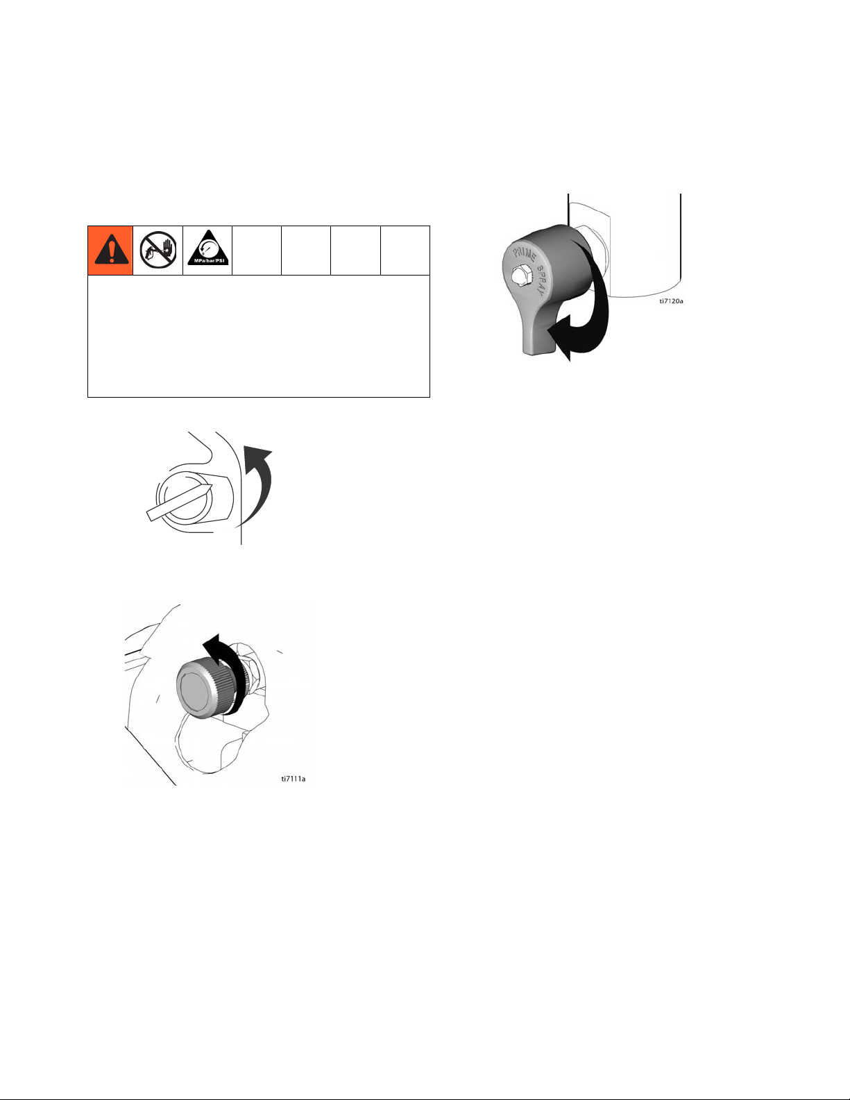
Pressure Relief Procedure
System pressure must be manually relieved to prevent
it from starting or spraying accidentally. Fluid under
high pressure can be injected into the skin and cause
serious injury. To reduce risk of injury from injection,
follow this procedure whenever you are instructed to
relieve pressure, stop spraying, service equipment or
install or clean spray tip (read Warnings, page 2).
1. Set pump valve OFF. Turn engine OFF.
TIA
2. Turn pressure to lowest setting. Trigger gun into pail
to relieve pressure.
3. Open prime valve (vertical).
If you suspect that the spray tip or hose is completely
clogged, or that pressure has not been fully relieved
after following the steps above, VERY SLOWLY, loosen
tip guard retaining nut or hose end coupling to relieve
pressure gradually, then loosen completely. Then clean
tip and hose.
311485J 3
Page 4
Service
Service
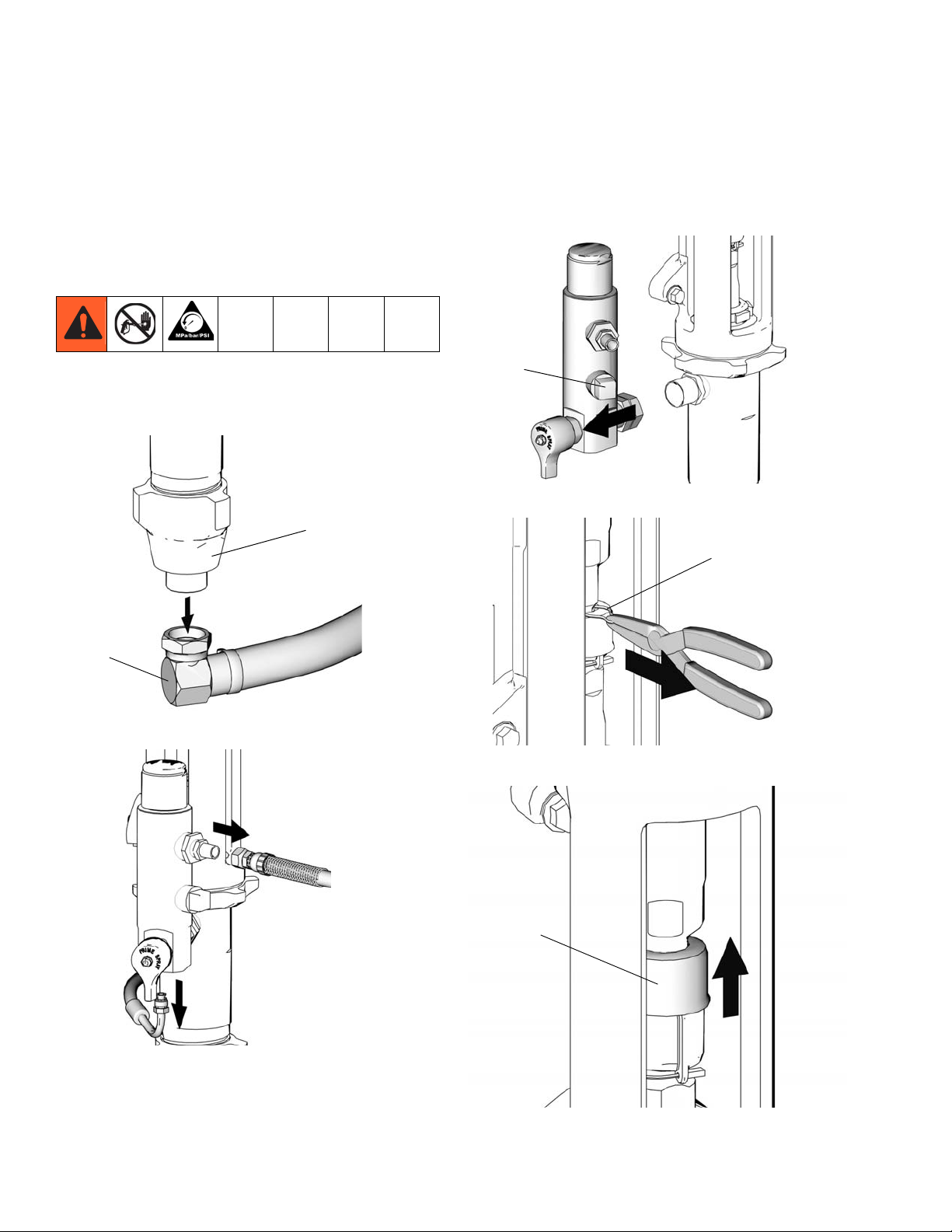
Removal
1. Flush pump (36). Stop pump on down stroke if possible.
2. Perform Pressure Relief Procedure, page 3.
3. Remove suction set (147) from pump (36).
36
5. Using a wrench, loosen filter housing fitting (110)
and remove housing from pump.
110
ti7119b
6. Using a pliers, remove clip (121).
121
147
ti7597b
4. Remove paint and drain lines from filter housing.
ti7845b
ti7789b
7. Slide cover (124) up.
124
ti7816b
4 311485J
Page 5

Service
8. Separate coupling (125) and remove.
125
ti7814b
9. Using a hammer, loosen jam nut (122). Unscrew
pump (36) from power head.
Ball Adjustment
1. Using a hammer, loosen and remove intake valve
(213).
213
ti7875b
2. Disassemble and clean all parts and o-rings (207).
209
215
122
36
10. Remove pump (36).
ti7782b
214
207
212
213
ti7879b
3. Select proper ball travel for material sprayed. Reassemble as shown.
Shortest Ball Travel
(for light material)
Longest Ball Travel
(for heavy material)
36
ti7804b
311485J 5
ti7881a
ti7874a
Page 6

Service
Piston Rod Assembly
1. Tap piston rod out of cylinder with a hammer or flip
over and tap piston rod out against bench.
NOTE: Sleeve may come out of cylinder with piston
rod.
2. If piston rod and sleeve did not separate, invert piston rod (222) and sleeve (220) and pound on hard
surface until piston rod comes out of sleeve.
ti7877a
4. Remove parts. Note orientation of parts for reassembly.
222
218
223
Lips Up
203
Lips Up
219
206
210
ti7878a
5. Clean all parts with a compatible solvent and
inspect them for wear or damage. Replace any worn
parts.
Component Rupture Hazard. Do not clean or wipe
piston valve threads. Cleaning the piston valve threads
could destroy the special sealing patch and cause the
piston valve to come loose during operation, causing
pump bursting and possible serious bodily injury.
3. Hold piston valve (210) securely in vice. Using a
wrench, separate piston valve (210) from rod (222).
Reassembly
1. Soak all leather packings (237) in SAE 30W oil for at
least 1 hour prior to assembly.
2. Alternately stack V-Packings (203) and V-Packings
(223).
208
Torque to 200
ft.-lb (272 N.m)
223
Lips Up
222
218
203
Lips Up
219
206
210
ti7880a
6 311485J
ti7878a
Page 7

Service
3. Grease piston rod (222) packings and top edge of
sleeve (220).
222
220
ti7898a
4. Carefully slide piston rod assembly (222) into top
edge of sleeve (220).
222
6. Grease o-ring (207) and place on sleeve. Slide one
o-ring (207) inside cylinder (205). Slide sleeve/piston rod assembly (222) into bottom of cylinder.
207
222
205
ti7895a
207
7. Install male gland (204) in cylinder (205).
8. Alternately stack UHMWPE packings (238) and
leather packings (237) (note orientation).
220
ti7896a
5. Grease top inch or two of piston rod (222) that will
go through the cylinder throat packings.
222
ti7897a
9. Place female gland (217) in top of cylinder. Loosely
install packing nut (202) and plug (201).
201
202
217
237
Lips Down
238
Lips Down
204
222
205
ti7884a
311485J 7
Page 8

Service
10. Reassemble intake valve (213) as shown.
209
215
214
207
212
213
ti7873a
11. Place intake valve (213) assembly in vice. Install
cylinder (205) assembly to intake valve. Torque to
350 ft-lb (475 N•m).
14. Hand tighten jam nut (122). Then tighten securely
1/8 to 1/4 turn with hammer or torque to 330 ft-lb
(447.4 N•m).
122
ti7817a
15. Install coupling (125) around pump rod.
125
ti7882a
12. Torque packing nut (202) down to 50 ft-lb (68 N•m).
13. Screw jam nut (122) to bottom of pump threads
(36). Screw pump completely up into power head.
122
ti7779a
36
ti7771a
16. Slide cover (124) over coupling (125).
124
125
ti7815a
8 311485J
Page 9

Service
17. Replace clip pin (121) to secure.
18. Reinstall filter housing (110).
110
ti7809a
19. Connect suction hose (147) to pump outlet (36).
36
121
125
ti7764a
147
ti7772a
311485J 9
Page 10

Parts
Parts
Ref. Part Description Qty.
201* 116385 PLUG 1
202 15G198 NUT, packing 1
203* 15G285 V-PACKING, UHMWPE, blue 3
204* 15H250 GLAND, male, throat 1
205 287836 CYLINDER, pump 1
206* 102972 BALL, sst, 0.875 in. 1
207*† 116377 PACKING, o-ring 3
208 15G196 GUIDE, ball 1
209 197306 SHIM, inlet 3
210 287837 VALVE, piston 1
212† 287838 SEAT, carbide, includes 214 and
207
213 15G195 HOUSING, intake (foo) 1
214*† 108001 BALL, sst, 1.5 in. 1
215 15G199 GUIDE, ball 1
Assemble with lips facing up
2
Assemble with lips facing down
1
201
202
217
1
237
Ref. Part Description Qty.
216 15H335 FITTING, nipple, 1 inch NPT 1
217* 15H251 GLAND, female, piston steel 1
218* 15G282 GLAND, male 1
219* 15G283 GLAND, female 1
220 287833 SLEEVE, cylinder 1
222 287832 ROD, piston 1
223* 15G284 V-PACKING, brown 2
237* 184307 PACKING, vee, leather 2
238* 108451 PACKING, vee, (UHMWPE) 3
* These parts are included in repair kit 287835, which
1
may be purchased separately.
† These parts are also included in Carbide Seat Kit
287838, which may be purchased separately.
238
1
205
2
208
218
203
219
204
222
206
210
223
216
207
220
207
209
215
2
214
207
212
213
ti7630a
10 311485J
Page 11

Notes
Notes
311485J 11
Page 12

Graco Standard Warranty
Graco warrants all equipment referenced in this document which is manufactured by Graco and bearing its name to be free from defects in
material and workmanship on the date of sale to the original purchaser for use. With the exception of any special, extended, or limited warranty
published by Graco, Graco will, for a period of twelve months from the date of sale, repair or replace any part of the equipment determined by
Graco to be defective. This warranty applies only when the equipment is installed, operated and maintained in accordance with Graco’s written
recommendations.
This warranty does not cover, and Graco shall not be liable for general wear and tear, or any malfunction, damage or wear caused by faulty
installation, misapplication, abrasion, corrosion, inadequate or improper maintenance, negligence, accident, tampering, or substitution of
non-Graco component parts. Nor shall Graco be liable for malfunction, damage or wear caused by the incompatibility of Graco equipment with
structures, accessories, equipment or materials not supplied by Graco, or the improper design, manufacture, installation, operation or
maintenance of structures, accessories, equipment or materials not supplied by Graco.
This warranty is conditioned upon the prepaid return of the equipment claimed to be defective to an authorized Graco distributor for verification of
the claimed defect. If the claimed defect is verified, Graco will repair or replace free of charge any defective parts. The equipment will be returned
to the original purchaser transportation prepaid. If inspection of the equipment does not disclose any defect in material or workmanship, repairs will
be made at a reasonable charge, which charges may include the costs of parts, labor, and transportation.
THIS WARRANTY IS EXCLUSIVE, AND IS IN LIEU OF ANY OTHER WARRANTIES, EXPRESS OR IMPLIED, INCLUDING BUT NOT LIMITED
TO WARRANTY OF MERCHANTABILITY OR WARRANTY OF FITNESS FOR A PARTICULAR PURPOSE.
Graco’s sole obligation and buyer’s sole remedy for any breach of warranty shall be as set forth above. The buyer agrees that no other remedy
(including, but not limited to, incidental or consequential damages for lost profits, lost sales, injury to person or property, or any other incidental or
consequential loss) shall be available. Any action for breach of warranty must be brought within two (2) years of the date of sale.
GRACO MAKES NO WARRANTY, AND DISCLAIMS ALL IMPLIED WARRANTIES OF MERCHANTABILITY AND FITNESS FOR A
PARTICULAR PURPOSE, IN CONNECTION WITH ACCESSORIES, EQUIPMENT, MATERIALS OR COMPONENTS SOLD BUT NOT
MANUFACTURED BY GRACO. These items sold, but not manufactured by Graco (such as electric motors, switches, hose, etc.), are subject to
the warranty, if any, of their manufacturer. Graco will provide purchaser with reasonable assistance in making any claim for breach of these
warranties.
In no event will Graco be liable for indirect, incidental, special or consequential damages resulting from Graco supplying equipment hereunder, or
the furnishing, performance, or use of any products or other goods sold hereto, whether due to a breach of contract, breach of warranty, the
negligence of Graco, or otherwise.
FOR GRACO CANADA CUSTOMERS
The Parties acknowledge that they have required that the present document, as well as all documents, notices and legal proceedings entered into,
given or instituted pursuant hereto or relating directly or indirectly hereto, be drawn up in English. Les parties reconnaissent avoir convenu que la
rédaction du présente document sera en Anglais, ainsi que tous documents, avis et procédures judiciaires exécutés, donnés ou intentés, à la suite
de ou en rapport, directement ou indirectement, avec les procédures concernées.
Graco Information
For the latest information about Graco products, visit www.graco.com.
TO PLACE AN ORDER, contact your Graco distributor or call 1-800-690-2894 to identify the nearest distributor.
All written and visual data contained in this document reflects the latest product information available at the time of publication.
GRACO INC. AND SUBSIDIARIES • P.O. BOX 1441 • MINNEAPOLIS MN 55440-1441 • USA
Copyright 2006, Graco Inc. All Graco manufacturing locations are registered to ISO 9001.
Graco reserves the right to make changes at any time without notice.
For patent information, see www.graco.com/patents.
Original instructions. This manual contains English. MM 311485
Graco Headquarters: Minneapolis
International Offices: Belgium, China, Japan, Korea
www.graco.com
Revised September 2012
 Loading...