

Page 1
Instructions - Parts
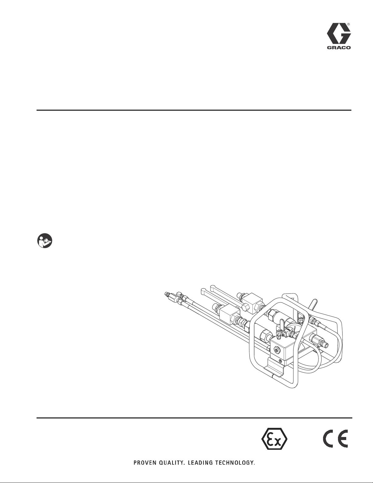
XM PFP Mix Manifold
Dual flush, center inject manifold with heated water circulating base for mixing
intumescent epoxies with the XM PFP system. For professional use only.
Part No. 262893
6000 psi (41 MPa, 414 bar) Maximum Working Pressure for A and B materials
4500 psi (31 MPa, 310 bar) Maximum Working Pressure for flushing fluid
100 psi (0.7 MPa, 7 bar) Maximum Working Pressure for heating fluid
180°F (82°C) Maximum Fluid Temperature
Important Safety Instructions
Read all warnings and instructions in this manual
and XM PFP Operation manual. Save all instructions.
3A2988B
EN
II2GcT5
ti20088a
Page 2

Related Manuals
Contents
RelatedManuals ...........................2
Warnings .................................3
Keep Components A and B Separate .........5
Changing Materials ...................... 5
Component Identification ...................6
Overview ..................................7
Installation ................................8
FluidInlets.............................. 8
SolventInlet ............................ 8
FluidOutlet ............................. 8
Heated Manifold .........................8
Mounting ............................... 8
Grounding ................................9
Flush Before Using Equipment ............... 9
Operation ................................10
Pressure Relief Procedure ................10
Flush .................................11
Dispensing and Spraying .................12
Volume Balancing the Mix Manifold .........13
Maintenance ..............................15
CleanStaticMixers ...................... 15
Clean Mix Manifold Outlet .................15
Troubleshooting .......................... 16
Repair ...................................17
Check Valves .......................... 17
Parts ....................................18
262890 Mix Manifold ..................... 18
TechnicalData ............................21
Graco Standard Warranty ...................22
GracoInformation ........................22
Related Manuals
Manuals are available at www.graco.com. Component
Manuals in English:
Manual Description
3A2776 XM PFP Operation
3A2989 XM PFP Repair - Parts
3A2799 XHF Spray Gun
2 3A2988B
Page 3
Warnings
Warnings
The following warnings are for the setup, use, grounding, maintenance, and repair of this equipment. The exclamation point symbol alerts you to a general warning and the hazard symbols refer to procedure-specific risks. When
these symbols appear in the body of this manual or on warning labels, refer back to these Warnings. Product-specific
hazard symbols and warnings not covered in this section may appear throughout the body of this manual where
applicable.
WARNING
WARNINGWARNINGWARNING
SKIN INJECTION HAZARD
High-pressure fluid from gun, hose leaks, or ruptured components will pierce skin. This may look like just
a cut, but it is a serious injury that can result in amputation. Get immediate surgical treatment.
• Do not spray without tip guard and trigger guard installed.
• Engage trigger lock when not spraying.
• Do not point gun at anyone or at any part of the body.
• Do not put your hand over the spray tip.
• Do not stop or deflect leaks with your hand, body, glove, or rag.
• Follow the Pressure Relief Procedure when you stop spraying and before cleaning, checking, or
servicing equipment.
• Tighten all fluid connections before operating the equipment.
• Check hoses and couplings daily. Replace worn or damaged parts immediately.
FIRE AND EXPLOSION HAZARD
Flammable fumes, such as solvent and paint fumes, in work area can ignite or explode. To help prevent
fire and explosion:
• Use equipment only in well ventilated area.
• Eliminate all ignition sources; such as pilot lights, cigarettes, portable electric lamps, and plastic drop
cloths (potential static arc).
• Keep work area free of debris, including solvent, rags and gasoline.
• Do not plug or unplug power cords, or turn power or light switches on or off when flammable fumes
are present.
• Ground all equipment in the work area. See Grounding instructions.
• Use only grounded hoses.
• Hold gun firmly to side of grounded pail when triggering into pail. Do not use pail liners unless they
are antistatic or conductive.
• Stop operation immediately if static sparking occurs or you feel a shock. Do not use equipment
until you identify and correct the problem.
• Keep a working fire extinguisher in the work area.
3A2988B 3
Page 4

Warnings
WARNING
WARNINGWARNINGWARNING
EQUIPMENT MISUSE HAZARD
Misuse can cause death or serious injury.
• Do not operate the unit when fatigued or under the influence of drugs or alcohol.
• Do not exceed the maximum working pressure or temperature rating of the lowest rated system
component. See Technical Data in all equipment manuals.
• Use fluids and solvents that are compatible with equipment wetted parts. See Technical Data in all
equipment manuals. Read fluid and solvent manufacturer’s warnings. For complete information
about your material, request MSDS from distributor or retailer.
• Do not leave the work area while equipment is energized or under pressure.
• Turn off all equipment and follow the Pressure Relief Procedure when equipment is not in use.
• Check equipment daily. Repair or replace worn or damaged parts immediately with genuine manufacturer’s replacement parts only.
• Do not alter or modify equipment. Alterations or modifications may void agency approvals and create
safety hazards.
• Make sure all equipment is rated and approved for the environment in which you are using it.
• Use equipment only for its intended purpose. Call your distributor for information.
• Route hoses and cables away from traffic areas, sharp edges, moving parts, and hot surfaces.
• Do not kink or over bend hoses or use hoses to pull equipment.
• Keep children and animals away from work area.
• Comply with all applicable safety regulations.
TOXIC FLUID OR FUMES HAZARD
Toxic fluids or fumes can cause serious injury or death if splashed in the eyes or on skin, inhaled, or
swallowed.
• Read MSDSs to know the specific hazards of the fluids you are using.
• Store hazardous fluid in approved containers, and dispose of it according to applicable guidelines.
PERSONAL PROTECTIVE EQUIPMENT
Wear appropriate protective equipment when in the work area to help prevent serious injury, including
eye injury, hearing loss, inhalation of toxic fumes, and burns. This protective equipment includes but is
not limited to:
• Protective eyewear, and hearing protection.
• Respirators, protective clothing, and gloves as recommended by the fluid and solvent manufacturer
4 3A2988B
Page 5
Keep Components A and B Separate
Cross-contamination can result in cured material in
fluid lines which could cause serious injury or damage
equipment. To prevent cross-contamination:
• Never interchange component A and component
B wetted parts.
• Never use solvent on one side if it has been contaminated from the other side.
Changing Materials
NOTICE
Changing the material types used in your equipment
requires special attention to avoid equipment damage
and downtime.
Warnings
• When changing materials, flush the equipment
multiple times to ensure it is thoroughly clean.
• Always clean any fluid inlet strainers after
flushing.
• Check with your material manufacturer for
chemical compatibility.
• When changing between epoxies and urethanes
or polyureas, disassemble and clean all fluid
components and change hoses. Epoxies often
have amines on the B (hardener) side. Polyureas
often have amines on the B (resin) side.
3A2988B 5
Page 6

Component Identification
Component Identification
C
A
G
V
F
J
B
D
M
H
E
P
K
R
X
L*
S*, W*
T1*
ti20089a
FIG. 1: Typical Installation
Key:
A A (Resin) Supply Inlet, 3/4 npt(m)
B B (Hardener) Supply Inlet, 1/2 npt (m)
C A (Resin) Ball Valve and Shutoff Handle
D B (Hardener) Ball Valve and Shutoff Handle
E Fluid Pressure Gauge
F A (Resin) Solvent Inlet Valve, 1/4 npt(m)
G B (Hardener) Solvent Inlet Valve
H Main Solvent Inlet
J A (Resin) Check Valve
K B (Hardener) Check Valve
L *Integrator Hose
T2*
Y*
ti20090a
M A (Resin) Solvent Check
P B (Hardener) Injector (not visible; inside outlet R)
R Mix Manifold Outlet, 1/2 x 1/2 male
S *Static Mixer Housing
T1 *Mix Hose
T2 *Fluid Whip Hose
U *Airless Spray Gun
V B (Hardener) Solvent Check
W *Static Mixing Element (not visible; inside tube S)
X Heated Water Circulation Plate
Y *Swivel Accessory 207946
* Not included in mix manifold kit.
U*
6 3A2988B
Page 7
Overview
Overview
The left side of the mix manifold is intended for the major
volume material, or the higher viscosity material if using
a 1:1 volume mix. This side is referred to throughout the
manual as the resin side or “A” side. The right side is
referred to as the hardener side or “B” side.
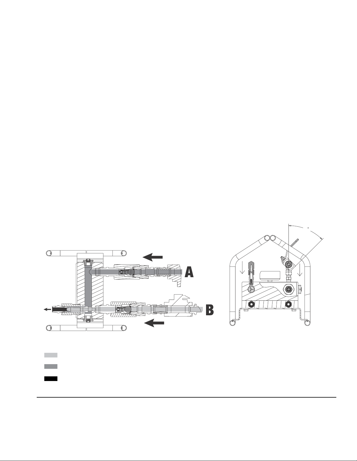
See FIG. 2 to view flow of A and B material inside the
XM PFP Mix Manifold.
The resin and hardener enter the manifold through the
manifold inlet ports. The A material flows through the
manifold to the material outlet port. The injector tube
creates a hollow stream of A material for the B material
to combine with once the hardener exits the injector (P).
The resin and hardener materials enter the mix manifold
outlet (R) before the materials enter the first length of
integrator fluid hose (L). The materials then pass
through the mixer assembly (S) where they are thoroughly mixed. Then they pass through a length of mix
hose (T1) where the continue to be lightly mixed before
entering the fluid whip hose (T2) then the gun (U).
Top View
Follow these recommendations for setup (see FIG.1on
page 6):
• Useatleasta1/2in.(12mm)x2ft(0.6m)integrator hose (L) connected to the mix manifold outlet
• Use at least 12 elements in the static mixer after the
integration hose and before the mix hose (T1).
• Useatleasta1/2in.(12mm)x10ft(3.0m)mix
hose (T1) after the static mixer and before the spray
gun.
Front View
45
SECTION
A-A
AB
SECTION
B-B
ti20091a
UBKGUZ
Hardener
Resin
Combined Material
F
IG. 2: Cutaway View
3A2988B 7
Page 8

Installation
Installation
The mix manifold is designed for use on proportioning
pumps with independent drive motors. Do not use this
manifold on a mechanically linked sprayer without
using mechanically linked on/off A and B valves as
this will result in fluid pressures that can rupture equipment and cause skin injection.
For assistance in setting up a plural component sprayer,
contact your Graco distributor, to ensure that you select
the proper type and size equipment for your system.
Fluid Inlets
See FIG. 1 on page 6. The A and B fluid inlets are
equipped with 3/4 in. check valves, ball valves, and
3/4 in. x 3/4 in. npt fittings and 3/4 in. x 1/2 in. fitting.
Connect 3/4 in. and 1/2 in. npsm(f) fluid hoses using the
two adapter nipples.
Mounting
To mount the bare manifold, drill four holes in the mounting surface, and secure with four 5/16-18 x 1/2 in.
(50 mm long) screws. Use the manifold as a template
when drilling the holes.
Solvent Inlet
See FIG. 1 on page 6. Connect the solvent supply line
from the solvent pump to the 1/4 npt(m) solvent inlet
valve (H). Use a grounded, Graco-approved hose rated
to withstand the maximum fluid working pressure of the
solvent pump. The solvent chosen must be chemically
compatible with the hose core material.
Fluid Outlet
See FIG. 1 on page 6. Connect the 1/2 in. ID x 2 ft. (minimum) integrator hose (L) to the mix manifold fluid outlet
(R). Then connect the static mixer (S) and mix hose (T1)
to the 1/2 npt(f) integrator hose (L). Then connect the
fluid whip hose (T2) to the mix hose and the gun to the
whip hose.
Heated Manifold
See FIG. 1 on page 6. The XM PFP manifold has a 1 in.
thick aluminum plate with brass compression fittings for
1/2 in. OD x 3/8 in. ID nylon hose used to circulate
heated water/glycol and heat the mix manifold.
8 3A2988B
Page 9

Grounding
Grounding
The equipment must be grounded to reduce the risk
of static sparking. Static sparking can cause fumes
to ignite or explode. Grounding provides an escape
wire for the electric current.
• Pump: use a ground wire and clamp as instructed
in your XM PFP sprayer operation manual.
• Air and fluid hoses: use only electrically conductive hoses with a maximum of 500 ft (150 m) combined hose length to ensure grounding continuity.
Check electrical resistance of hoses. If total resistance to ground exceeds 29 megohms, replace
hose immediately.
• Mix manifold and solvent flush system: use only
a Graco approved grounded solvent hose. Not all
heated hoses are grounded, and the mix manifold
primary ground is through the solvent hose. Ensure
that the solvent pump is properly grounded, as
instructed in your solvent pump manual. Ensure
there is electrical continuity from the spray tip to the
grounded solvent hose.
Flush Before Using Equipment
The equipment was tested with lightweight oil, which is
left in the fluid passages to protect parts. To avoid contaminating your fluid with oil, flush the equipment with a
compatible solvent before using the equipment. See
Flush, page 11.
• Air compressor: Follow manufacturer’s recommendations.
• Spray gun: ground through connection to a properly grounded fluid hose and pump.
• Fluid supply container: follow local code.
• Object being sprayed: follow local code.
• Solvent pails used when flushing: follow local
code. Use only conductive metal pails, placed on a
grounded surface. Do not place the pail on a nonconductive surface, such as paper or cardboard,
which interrupts grounding continuity.
• To maintain grounding continuity when flushing
or relieving pressure: hold metal part of the spray
gun firmly to the side of a grounded metal pail, then
trigger the gun.
3A2988B 9
Page 10

Operation
Operation
Pressure Relief Procedure
Follow the Pressure Relief Procedure whenever
you see this symbol.
This equipment stays pressurized until pressure is
manually relieved. To help prevent serious injury
from pressurized fluid, such as skin injection,
splashing fluid and moving parts, follow the Pressure
Relief Procedure when you stop spraying and before
cleaning, checking, or servicing the equipment.
Relieve A and B Fluid Pressure
1. Engage trigger lock.
6. Disengage trigger lock.
ti19265a1
7. Hold a metal part of the gun firmly to a grounded
metal pail with a splash guard in place. Trigger gun
to relieve pressure in material hoses.
ti19269a
ti19265a1
2. Press Stop to turn sprayer OFF.
3. Close all air motor supply valves or any source of
fluid pressure.
4. If fluid heaters are used, shut them off using the
controls on the display module.
5. Shut off RAM air supply.
8. Engage trigger lock.
9. Close the mix manifold inlet ball valves (C, D).
10. Flush mixed material hoses, mixer, and gun. See
Flush on page 11.
10 3A2988B
Page 11

Operation
Flush
The equipment must be grounded to reduce the risk of
static sparking. Static sparking can cause fumes to
ignite or explode. Grounding provides an escape wire
for the electric current.
If your system uses heaters, shut off the main power
to the heaters and heated hose control and allow to
cool before flushing.
NOTICE
To prevent fluid from curing in the equipment, flush
the system frequently. Be sure there is an adequate
supply of flushing fluid before spraying.
NOTE:
• Ensure the chosen flushing fluid is compatible with
dispense fluid and the equipment wetted parts.
3. Close mix manifold inlet ball valves.
ti20129a
4. Open solvent inlet valves.
• Solvent may channel through viscous fluids and
leave a coating of mixed fluid on the inner tube of
your hose. Be sure all fluid is thoroughly flushed from
the hose after each use.
• Remove spray tip for more thorough cleaning of the
whip hose and static mixers.
• Use heated water or choose a solvent that dissolves
the material you are mixing.
• Always leave equipment filled with fluid to avoid drying and scaling.
1. Relieve pressure; see page 10.
2. Engage trigger lock. Remove spray tip and trigger
guard assembly.
ti20093a
5. Turn on solvent flush pump.
6. Disengage spray gun trigger lock.
ti19265a2
7. Trigger gun into a grounded metal pail with lid. Use
a lid with a hole to dispense through to avoid splashing.
ti19265a1
3A2988B 11
ti19266
Page 12

Operation
8. Cycle the solvent flush ball valves on and off independently several times to be sure both sides are
thoroughly flushed. Continue flushing until clean solvent dispenses.
ti19269a
9. Turn off solvent pump air supply.
10. Hold the metal part of the gun firmly to a grounded
metal pail with lid in place. Trigger gun until all fluid
pressure is relieved.
11. Engage trigger lock.
12. Close solvent inlet valves.
Dispensing and Spraying
1. Close solvent inlet valves.
ti20095a
2. Open mix manifold inlet ball valves.
ti20095a
ti20128a
3. Ensure sprayer is in “spray” mode and push the
green START button.
4. Disengage spray gun trigger lock.
ti19265a2
5. Hold the metal part of the gun firmly to a grounded
metal pail with a lid to avoid splashing. Trigger the
gun until mixed coating material is evident and
flushing fluid is gone.
6. Proceed to spraying.
12 3A2988B
Page 13

Operation
Volume Balancing the Mix Manifold
Ratio errors can occur between the sprayer and the mix
manifold even when the sprayer output ratio is accurate.
The following can occur when the hoses are not volume
balanced to the mix ratio:
• Hoses fill to high pressure while metering on-ratio.
• Only the A material hose rises to spray pressure.
• Off-ratio at the mix point until hose pressures equalize.
Lead/Lag Imbalance
When resin and hardener volume requirements (ratio)
and/or viscosities are different an imbalance can occur
each time the gun is triggered. This occurs because the
fluids can rush out of the manifold near a 1:1 ratio before
the sprayer starts.
To avoid this imbalance:
• Pressurize hoses to spray pressure before starting
spray mode.
Hose Selection
Hoses should be sized to match the hose volume ratio
to the mix ratio. The hose size should also allow for minimum pressure drop on the major volume side to meet
your flow requirements.
Use Table 1 to match mix ratio, hose selection, and volume ratio. Use Table 2 on page 14 to reference amount
of pressure drop for 50 ft lengths of different hose sizes.
Size hoses to:
• Minimize pressure drop on the high volume and
often higher viscosity resin side to achieve higher
flow and pressure at the gun while spraying.
• Allow both A and B material hoses to come up to
spray pressure together when A and B fluids are
metered into the hoses on ratio.
• Balance the inherent stall pressure between the
resin A and hardener B sides when the gun closes
and also when triggered. This reduces the lead/lag
error at the mix point when the spray gun is triggered.
• Size the fluid delivery hose volume to nearly match
the mix ratio. See Table 1.
Table 1: Volume Ratio of A to B Hose
Hose
Selection
Mix Ratio
1:1 3/4 x 3/4 1.00:1
2:1 3/4 x 1/2 2.25:1
3:1 3/4 x 1/2 2.25:1
4:1 to 6:1 1/2 x 1/4 4.00:1
4:1 to 8:1 3/4 x 3/8 4.00:1
6:1 to 10:1 1/2 x 3/16 7.00:1
8:1 to 10:1 3/4 x 1/4 8.80:1
Example: At a 4:1 mix ratio, a 1/2 in. ID resin hose and
a 1/4 in. ID hardener hose matches the 4:1 volume ratio.
AxB
1/2x1/2
3/8x3/8
1/2 x 3/8 1.78:1
3/8 x 1/4 2.25:1
3/8 x 1/4 2.25:1
Hose Volume
Ratio
3A2988B 13
Page 14

Operation
Table 2: Hose Selection by Pressure Drop
Hose ID
(in.)
Pressure drop in psi
(per 50 ft section per 1,000
cps at 1 gal/min.)
Pressure Drop in bar
(per 15.24 meter section per
1,000 cps at 1 liter/min.)
1/8 55,910 1,018
3/16 11,044 201
1/4 3,494 64
3/8 690 13
1/2 218 4
5/8 89 1.62
3/4 43 0.78
Reference Formula
Total Pressure Drop=PxVxLxF
Key:
P= Pressure drop from chart
V = Viscosity in centipoise /1000
L= Length of hose in feet / 50
F= Flow rate in gallons per minute
Example #1: What is the pressure loss of a 2,000 cps
material through 150 ft of 3/8 in. ID hose at 0.75 gpm?
690 psi (from chart) x 2 (2,000 cps /1,000) x 3 (150 ft / 3)
x 0.75 (gpm) = 3105 psi loss
This is a lot of pressure loss before reaching the spray
gun. Continue to Example #2 which examines the same
situation but with a 1/2 in. ID hose.
Example #2: What is the pressure loss of a 2,000 cps
material through 150 ft of 1/2 in. ID hose at 0.75 gpm?
218 psi (from chart) x 2 (2,000 cps /1,000) x 3 (150 ft / 3)
x 0.75 (gpm) = 981 psi loss
14 3A2988B
Page 15

Maintenance
Clean Static Mixers
See FIG. 1, page 6. One 12 element mixer is attached
(S, Part No. 262478) to the integrator hose (L). This
housing uses mix elements, available in a package of 25
(W, Part No. 248927).
NOTICE
Never use a swivel union on the mixer inlets. The
union will compress the tube and make it impossible
to remove the mix element.
Clean Mix Manifold Outlet
1. Remove outlet fitting (33) to expose B center injection tube (9).
Maintenance
9
ti20096a
2. Clean any build-up on, around, or inside the
tube (9).
3. Reinstall outlet fitting (33).
33
3A2988B 15
Page 16

Troubleshooting
Troubleshooting
1. Relieve the pressure before you check or service
any system equipment.
2. Check all possible causes and solutions in the troubleshooting chart before disassembling the manifold.
Problem Cause Solution
Little or no resin output. Fluid inlet is plugged. Clean inlet; remove obstruction. See
Clean Mix Manifold Outlet, page 15.
Fluid container is empty. Refill.
Little or no hardener output. Fluid inlet is plugged. Clean inlet; remove obstruction. See
Clean Mix Manifold Outlet, page 15.
Fluid container is empty. Refill.
Mixed fluid will not flush out. Fluid is hardened in static mixers or whip
hose.
Solvent supply container is empty. Refill.
Solvent is not compatible with fluid. Change to compatible solvent.
Hardener pressure higher than normal. Hardener is cold. Correct heat problem. See fluid heater
Hardener pressure lower than normal. Resin is cold. Flow rate is low. Correct heat problem. See fluid heater
Spray pattern developing tails. Static mixer and/or whip hose plugging
up.
Low pressure from sprayer. Check air supply pressure. Check inlet air
Cold material. Increase heat. See XM PFP Plural-Com-
Too much pressure drop. Use larger hoses or more heat.
Resin or hardener does not shut off. Damaged ball or seat or seal in
valve (52).
Off ratio condition after increasing spray
pressure in spray mode with a remote mix
manifold.
Hoses not volume balanced. Volume balance A and B closer to volume
Clean with compatible solvent. See Main-
tenance, page 15. Replace as necessary.
section of XM PFP Plural-Component
Sprayer Repair manual 3A2989.
section of XM PFP Plural-Component
Sprayer Repair manual 3A2989.
Replace restrictor.
Clean Static Mixers, page 15.
Clean spray gun and tip. See gun manual.
gauges while spraying.
ponent Sprayer Operation manual
3A2776.
Replace or rebuild valve.
mix ratio. See Volume Balancing the
Mix Manifold, page 13.
16 3A2988B
Page 17

Repair
Follow Pressure Relief Procedure, page 10, when
you stop spraying and before cleaning, checking, servicing, or transporting equipment. Read warnings in
your sprayer manual.
NOTICE
• Be sure to label all fluid parts A or B when disassembling them. Doing so prevents interchanging
resin and hardener parts during reassembly,
which will contaminate the materials and the
fluid path through the equipment.
• Color-coded chemically resistant tape may be
used to label the parts. Use blue for resin and
green for hardener.
Repair
Check Valves
When replacing material check valves or solvent check
valves, reinstall with proper flow direction.
ti20094a
3A2988B 17
Page 18

Parts
Parts
262890 Mix Manifold
10
33
56
9
41
51
52
21
42
49
47
46
37
44
45
48
50
5
53
47
43
1
38
21
39
40, 55
ti20089a
NOTE: Apply pipe sealant to all non-swiveling threads.
18 3A2988B
Page 19

262890 Mix Manifold
Ref Part Description Qty
1 16T870 BLOCK, manifold 1
5 239018 VALVE, ball, stainless steel 2
9 126790 TUBE, injector, 1/4 npt 1
10 15R067 PIPE, outlet, mixer manifold 1
21 100721 PLUG, pipe 4
25 --- LUBRICANT, thread 1
26 --- SEALANT, pipe, stainless steel 1
33 158491 FITTING, nipple 1
37 157191 FITTING, adapter (1/2 npt x 3/4 npt) 1
38 160032 FITTING, nipple 5
39 262522 CARRIAGE, remote manifold 1
40 102547 SCREW, cap, hex head 4
41 16T294 PLATE, heater transfer 1
42 126692 FITTING, tube, npt x tube 2
43 114434 GAUGE, pressure, fluid, stainless
steel
44 15R875 FITTING, tee, 1/4 male x female x
female
45 100840 FITTING, elbow, street 1
46 162453 FITTING, (1/4 npsm x 1/4 npt) 2
47 H42503 HOSE, coupled, 4500 psi, 0.25 ID,
3ft
48 157676 FITTING, union swivel, 90 degree 2
49 157785 FITTING, swivel 2
50 501867 VALVE, check 2
51 C19681 BUSHING, pipe 2
52 126725 VALVE, ball, 3/4, 6000 psi 2
53 16T481 VALVE, check 2
53a 102595 O-RING 1
55 189285 WASHER, lock, spring 1
56▲ 189285 LABEL, hot surface 1
Parts
1
1
2
--- Not for sale.
▲ Replacement Danger and Warning labels, tags and
cards are available at no cost.
3A2988B 19
Page 20

Parts
20 3A2988B
Page 21

Technical Data
Technical Data
Maximum working pressure . . . 6000 psi (41 MPa, 414 bar) for A and B materials
4500 psi (31 MPa, 310 bar) for flushing fluid
100 psi (0.7 MPa, 7 bar) for heating fluid
Maximum fluid temperature . . . 180°F (82°C)
Fluidinlet ................. 3/4in.nptand3/4in.x1/2in.nipplefittings for 3/4 in. x 1/2 in. hoses
Fluidoutletsize............. 1/2in.npt(m)nipple
Solventinletvalves.......... 1/4in.npt(m)
Heated fluid ports ........... 1/4in.npt(f)
Wettedparts............... Manifold block and internal parts: PTFE, electroless nickel plated steel, zinc plated
steel
Flush valves and fittings: stainless steel, plated carbon steel, hardened alloy steel,
acetal, PTFE
Fluid ball valves: plated carbon steel, acetal, PTFE, FKM
Fluid check valves: plated carbon steel, carbide seat, PTFE, alloy steel ball
3A2988B 21
Page 22

Graco Standard Warranty
Graco warrants all equipment referenced in this document which is manufactured by Graco and bearing its name to be free from defects in
material and workmanship on the date of sale to the original purchaser for use. With the exception of any special, extended, or limited warranty
published by Graco, Graco will, for a period of twelve months from the date of sale, repair or replace any part of the equipment determined by
Graco to be defective. This warranty applies only when the equipment is installed, operated and maintained in accordance with Graco’s written
recommendations.
This warranty does not cover, and Graco shall not be liable for general wear and tear, or any malfunction, damage or wear caused by faulty
installation, misapplication, abrasion, corrosion, inadequate or improper maintenance, negligence, accident, tampering, or substitution of
non-Graco component parts. Nor shall Graco be liable for malfunction, damage or wear caused by the incompatibility of Graco equipment with
structures, accessories, equipment or materials not supplied by Graco, or the improper design, manufacture, installation, operation or
maintenance of structures, accessories, equipment or materials not supplied by Graco.
This warranty is conditioned upon the prepaid return of the equipment claimed to be defective to an authorized Graco distributor for verification of
the claimed defect. If the claimed defect is verified, Graco will repair or replace free of charge any defective parts. The equipment will be returned
to the original purchaser transportation prepaid. If inspection of the equipment does not disclose any defect in material or workmanship, repairs will
be made at a reasonable charge, which charges may include the costs of parts, labor, and transportation.
THIS WARRANTY IS EXCLUSIVE, AND IS IN LIEU OF ANY OTHER WARRANTIES, EXPRESS OR IMPLIED, INCLUDING BUT NOT LIMITED
TO WARRANTY OF MERCHANTABILITY OR WARRANTY OF FITNESS FOR A PARTICULAR PURPOSE.
Graco’s sole obligation and buyer’s sole remedy for any breach of warranty shall be as set forth above. The buyer agrees that no other remedy
(including, but not limited to, incidental or consequential damages for lost profits, lost sales, injury to person or property, or any other incidental or
consequential loss) shall be available. Any action for breach of warranty must be brought within two (2) years of the date of sale.
GRACO MAKES NO WARRANTY, AND DISCLAIMS ALL IMPLIED WARRANTIES OF MERCHANTABILITY AND FITNESS FOR A
PARTICULAR PURPOSE, IN CONNECTION WITH ACCESSORIES, EQUIPMENT, MATERIALS OR COMPONENTS SOLD BUT NOT
MANUFACTURED BY GRACO. These items sold, but not manufactured by Graco (such as electric motors, switches, hose, etc.), are subject to
the warranty, if any, of their manufacturer. Graco will provide purchaser with reasonable assistance in making any claim for breach of these
warranties.
In no event will Graco be liable for indirect, incidental, special or consequential damages resulting from Graco supplying equipment hereunder, or
the furnishing, performance, or use of any products or other goods sold hereto, whether due to a breach of contract, breach of warranty, the
negligence of Graco, or otherwise.
FOR GRACO CANADA CUSTOMERS
The Parties acknowledge that they have required that the present document, as well as all documents, notices and legal proceedings entered into,
given or instituted pursuant hereto or relating directly or indirectly hereto, be drawn up in English. Les parties reconnaissent avoir convenu que la
rédaction du présente document sera en Anglais, ainsi que tous documents, avis et procédures judiciaires exécutés, donnés ou intentés, à la suite
de ou en rapport, directement ou indirectement, avec les procédures concernées.
Graco Information
For the latest information about Graco products, visit www.graco.com.
TO PLACE AN ORDER, contact your Graco distributor or call to identify the nearest distributor.
Phone: 612-623-6921 or Toll Free: 1-800-328-0211 Fax: 612-378-3505
All written and visual data contained in this document reflects the latest product information available at the time of publication.
GRACO INC. AND SUBSIDIARIES • P.O. BOX 1441 • MINNEAPOLIS MN 55440-1441 • USA
Copyright 2012, Graco Inc. All Graco manufacturing locations are registered to ISO 9001.
Graco reserves the right to make changes at any time without notice.
For patent information, see www.graco.com/patents.
Original instructions. This manual contains English. MM 3A2988
Graco Headquarters: Minneapolis
International Offices: Belgium, China, Japan, Korea
www.graco.com
Revised February 2013
 Loading...