

Page 1
Instructions - Parts
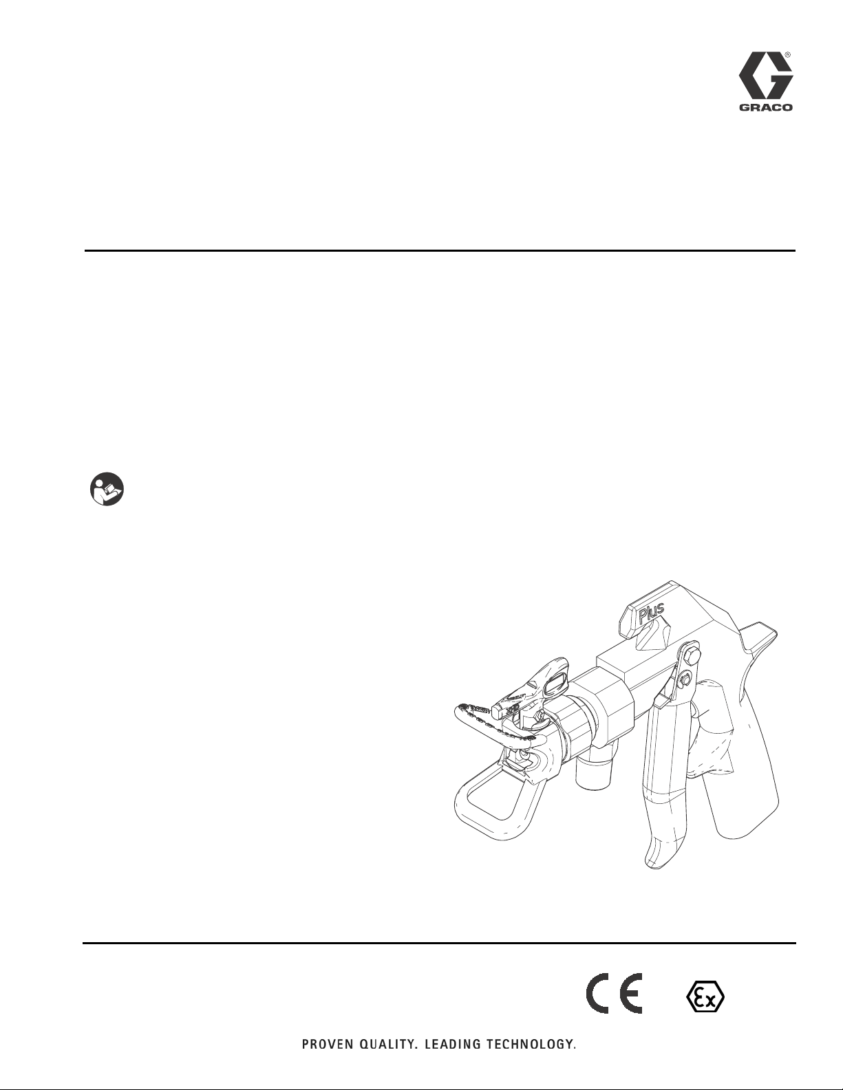
XHF Spray Gun
For spraying viscous materials at high flow rates. For professional use only.
Part No. 262854, Series A
Includes an XHD™RAC®Guard and XHD429 SwitchTip
7250 psi (50 MPa, 500 bar) Maximum Working Pressure
™
3A2799A
EN
Important Safety Instructions
Read all warnings and instructions in this
manual. Save all instructions.
ti19264a
II2GcT6
Page 2

Contents
Warnings .................................3
Operation .................................5
System Requirements ..................... 5
Ground the System ....................... 5
Gun Trigger Lock ........................5
Pressure Relief Procedure .................5
Operation .............................. 6
AdjusttheSprayPattern ................... 6
GunCare ..............................7
FlushtheGun ..........................8
Service ...................................9
Disassembly for Repair or Cleaning .......... 9
Reassembly ........................... 10
TesttheGunAfterService ................ 12
Parts ....................................13
Accessories ..............................14
TechnicalData ............................15
Graco Standard Warranty ...................16
GracoInformation .........................16
2 3A2799A
Page 3
Warnings
Warnings
The following warnings are for the setup, use, grounding, maintenance, and repair of this equipment. The exclamation point symbol alerts you to a general warning and the hazard symbols refer to procedure-specific risks. When
these symbols appear in the body of this manual or on warning labels, refer back to these Warnings. Product-specific
hazard symbols and warnings not covered in this section may appear throughout the body of this manual where
applicable.
WARNING
SKIN INJECTION HAZARD
High-pressure fluid from gun, hose leaks, or ruptured components will pierce skin. This may look like just
a cut, but it is a serious injury that can result in amputation. Get immediate surgical treatment.
• Do not spray without tip guard and trigger guard installed.
• Engage trigger lock when not spraying.
• Do not point gun at anyone or at any part of the body.
• Do not put your hand over the spray tip.
• Do not stop or deflect leaks with your hand, body, glove, or rag.
• Follow the Pressure Relief Procedure when you stop spraying and before cleaning, checking, or
servicing equipment.
• Tighten all fluid connections before operating the equipment.
• Check hoses and couplings daily. Replace worn or damaged parts immediately.
FIRE AND EXPLOSION HAZARD
Flammable fumes, such as solvent and paint fumes, in work area can ignite or explode. To help prevent
fire and explosion:
• Use equipment only in well ventilated area.
• Eliminate all ignition sources; such as pilot lights, cigarettes, portable electric lamps, and plastic drop
cloths (potential static arc).
• Keep work area free of debris, including solvent, rags and gasoline.
• Do not plug or unplug power cords, or turn power or light switches on or off when flammable fumes
are present.
• Ground all equipment in the work area. See Grounding instructions.
• Use only grounded hoses.
• Hold gun firmly to side of grounded pail when triggering into pail. Do not use pail liners unless they
are antistatic or conductive.
• Stop operation immediately if static sparking occurs or you feel a shock. Do not use equipment
until you identify and correct the problem.
• Keep a working fire extinguisher in the work area.
3A2799A 3
Page 4
Warnings
WARNING
EQUIPMENT MISUSE HAZARD
Misuse can cause death or serious injury.
• Do not operate the unit when fatigued or under the influence of drugs or alcohol.
• Do not exceed the maximum working pressure or temperature rating of the lowest rated system component. See Technical Data in all equipment manuals.
• Use fluids and solvents that are compatible with equipment wetted parts. See Technical Data in all
equipment manuals. Read fluid and solvent manufacturer’s warnings. For complete information
about your material, request MSDS from distributor or retailer.
• Do not leave the work area while equipment is energized or under pressure.
• Turn off all equipment and follow the Pressure Relief Procedure when equipment is not in use.
• Check equipment daily. Repair or replace worn or damaged parts immediately with genuine manufacturer’s replacement parts only.
• Do not alter or modify equipment. Alterations or modifications may void agency approvals and create
safety hazards.
• Make sure all equipment is rated and approved for the environment in which you are using it.
• Use equipment only for its intended purpose. Call your distributor for information.
• Route hoses and cables away from traffic areas, sharp edges, moving parts, and hot surfaces.
• Do not kink or over bend hoses or use hoses to pull equipment.
• Keep children and animals away from work area.
• Comply with all applicable safety regulations.
RECOIL HAZARD
Gun may recoil when triggered. If you are not standing securely, you could fall and be seriously injured.
TOXIC FLUID OR FUMES HAZARD
Toxic fluids or fumes can cause serious injury or death if splashed in the eyes or on skin, inhaled, or
swallowed.
• Read MSDSs to know the specific hazards of the fluids you are using.
• Store hazardous fluid in approved containers, and dispose of it according to applicable guidelines.
PERSONAL PROTECTIVE EQUIPMENT
Wear appropriate protective equipment when in the work area to help prevent serious injury, including
eye injury, hearing loss, inhalation of toxic fumes, and burns. This protective equipment includes but is
not limited to:
• Protective eyewear, and hearing protection.
• Respirators, protective clothing, and gloves as recommended by the fluid and solvent manufacturer
4 3A2799A
Page 5
Operation
Operation
Keep the wallet-sized warning card provided with this
gun with the operator at all times. The card contains
important treatment information should an injection
injury occur. Additional cards (part no. 222385) are
available at no charge from Graco.
System Requirements
Pressure drain valves are recommended in the system;
they assist in relieving fluid pressure in the displacement
pump, hose and gun in the event that the gun is clogged
and triggering the gun does not relieve all pressure.
Ground the System
The equipment must be grounded to reduce the risk
of static sparking. Static sparking can cause fumes to
ignite or explode. Grounding provides an escape wire
for the electric current.
Ground the pump and all other equipment used or
located in the spray area. Check your local electrical
code for detailed grounding instructions for your area
and type of equipment. Follow the grounding instructions provided in your pump or sprayer manual. Ground
the gun through connection to a properly grounded fluid
hose and pump or sprayer.
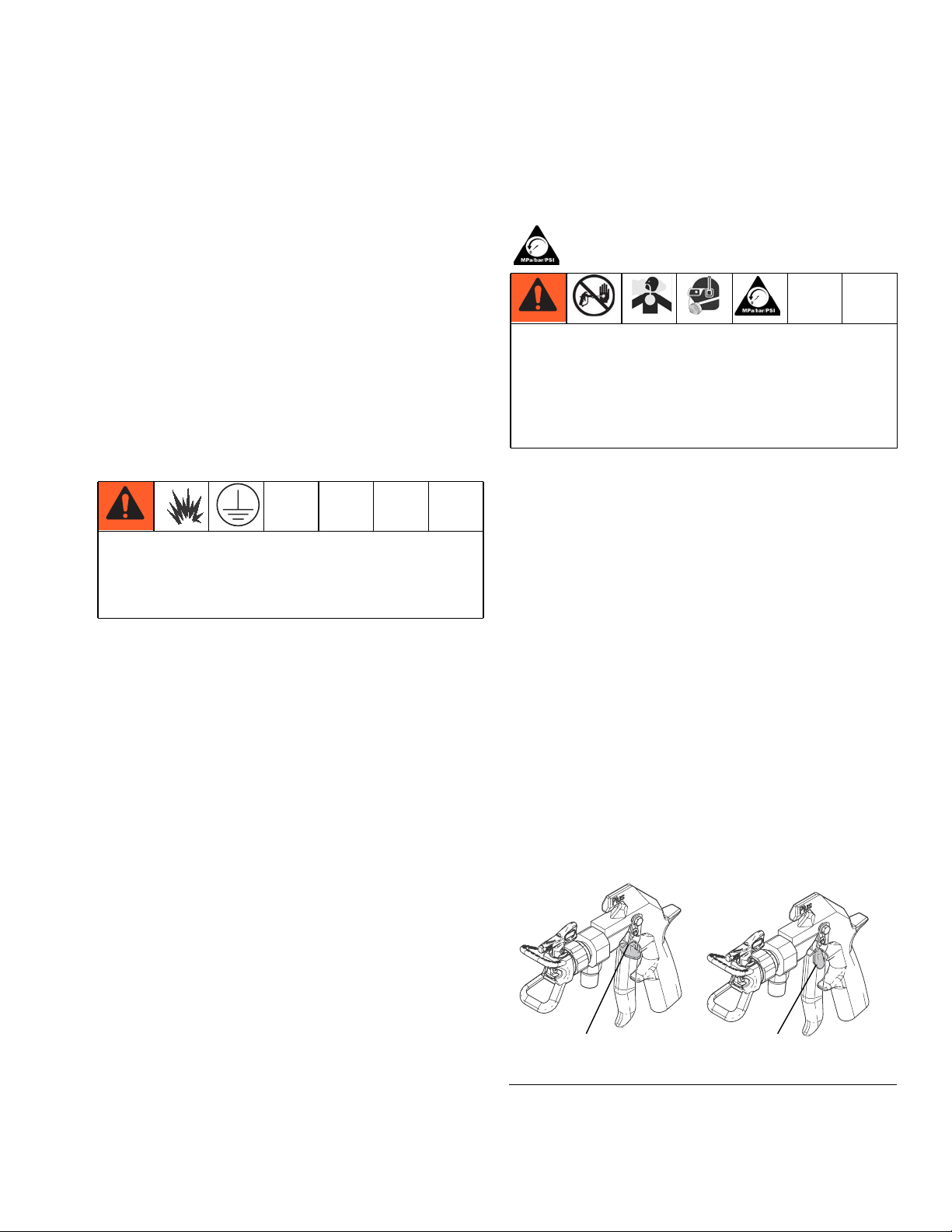
Gun Trigger Lock
1. To engage the gun trigger lock, rotate the lock so it
is perpendicular to the gun body. See FIG.1.
Pressure Relief Procedure
Follow the Pressure Relief Procedure whenever
you see this symbol.
This equipment stays pressurized until pressure is
manually relieved. To help prevent serious injury from
pressurized fluid, such as skin injection, splashing
fluid and moving parts, follow the Pressure Relief
Procedure when you stop spraying and before
cleaning, checking, or servicing the equipment.
1. Engage the gun trigger lock.
2. Shut off power to the pump.
3. Disengage the gun trigger lock.
4. Hold a metal part of the gun firmly to a grounded
metal pail. Trigger the gun to relieve pressure.
5. Engage the gun trigger lock.
6. Open the system drain valve, having a container
ready to catch the drainage. Observe the pressure
gauge. The gauge reads 0 psi/bar when fully
drained. Close the system drain valve.
7. If you suspect that the spray tip or hose is completely clogged or that pressure has not been fully
relieved after following the previous steps, very
slowly loosen the tip guard retaining nut or hose end
coupling to relieve pressure gradually. Clean the tip
or hose obstruction.
2. To disengage the gun trigger lock, push the lock out
and rotate it so it is parallel with the gun body. See
FIG.1.
ti19265a
Locked
FIG. 1: Trigger Lock Positions
3A2799A 5
Unlocked
Page 6

Operation
Operation
To reduce the risk of component rupture, and serious
injury, including fluid injection, do not exceed the
gun’s 7250 psi (500 bar, 50 MPa) maximum working
pressure or the maximum working pressure of lowest
rated component in the system.
ti19266a
Swivel
9
8
A
8. Use a full-open, full-close trigger action. Hold the
gun about 14 in. (350 mm) from and at right angles
to the work surface. Don’t swing the gun in an arc.
Practice to find the best length and speed of stroke.
Adjust the Spray Pattern
1. To adjust the spray pattern direction, relieve pressure. Loosen the tip guard retaining nut (B). Rotate
the tip guard as necessary to achieve a vertical or
horizontal spray pattern. See FIG. 3. Tighten the nut.
2. The spray tip orifice and spray angle determines the
coverage and size of pattern. When more coverage
is needed, use a larger spray tip rather than increasing fluid pressure.
NOTICE
Openings in the tip guard reduce material buildup on
the guard while spraying. Damage to the sharp edges
of the openings causes material to collect in the damaged area. To prevent this, never hang the gun by the
tip guard.
FIG.2
1. Connect a fluid hose (A) to the gun inlet. Use high
pressure swivel 207946 if desired (order separately). See Fig. 2.
2. With SwitchTip (8) and tip guard (9) removed, start
the pump. Flush the pump according to the instructions supplied with it. Use the lowest pressure possible.
3. Prime the system with the material.
4. Relieve pressure.
5. Install the SwitchTip (8) and tip guard (9). See FIG.
2.
6. Start the pump. Trigger the gun onto test paper.
Adjust the fluid pressure until the spray is completely atomized. Use the lowest pressure necessary to get the desired results. Higher pressure may
not improve the spray pattern and will cause premature tip and pump wear.
7. If adjusting the pressure does not give a good spray
pattern, relieve pressure and try another tip size.
A
FIG.3
B
C
ti19267a
6 3A2799A
Page 7

Operation
Gun Care
• To reduce the risk of fluid injection or splashing in
the eyes or on the skin, do not point gun at
anyone or at any part of the body when cleaning
or checking a clogged tip. Point the gun toward
the ground or into a waste container when
checking to see if the spray tip is cleared.
• Do not try to “blow back” material; this is not an
air spray gun.
• Do not wipe fluid buildup off the gun or spray tip
until pressure is relieved.
Cleaning during the day
1. Relieve pressure, page 5.
If the spray tip clogs while spraying
1. Stop spraying immediately.
2. Lock the gun trigger lock. Rotate the RAC SwitchTip
handle 180°. See Fig. 4.
3. Unlock the gun trigger lock. Trigger the gun into a
pail or onto the ground to remove the clog.
4. Lock the gun trigger lock. Rotate the tip handle back
to the spraying position.
5. If the tip is still clogged:
a. Engage the gun trigger lock.
b. Shut off the sprayer and disconnect the power
source.
c. Open the pressure drain valve to relieve pres-
sure.
d. Clean the spray tip as shown in manual 308644,
supplied with the RAC SwitchTip.
2. Use a solvent-soaked brush to clean the spray tip.
Clean the front of the tip frequently during the day to
help reduce buildup.
3. Clean the tip and tip guard at the end of each work
day.
NOTICE
Never soak the entire gun in solvent. Prolonged exposure to solvent can ruin the packings.
ti19268a
Spraying position shown. Rotate tip handle 180° and
trigger gun to clear clog.
FIG.4
3A2799A 7
Page 8

Operation
Flush the Gun
To reduce the risk of serious injury, including splashing
fluid in the eyes or on the skin, or static electric discharge when flushing:
• Be sure the entire system, including flushing pails,
is properly grounded.
• Remove the tip guard and spray tip.
• Maintain metal to metal contact between the gun
and the flushing pail.
• Use the lowest possible pressure.
ti19269a
7. Now trigger the gun into the flushing fluid supply
pail. Circulate the fluid until the system is thoroughly
flushed.
8. After gun is thoroughly flushed, relieve pressure.
NOTICE
Always flush the pump and gun before the sprayed
fluid cures.
NOTE: This procedure requires a grounded pail of compatible flushing fluid.
1. Relieve pressure.
2. Remove the tip guard and spray tip. Soak and clean
the parts.
3. Single component systems only: Remove the pump
intake from the original pail. Put the pump intake in
a grounded pail of compatible solvent.
4. Start the pump at its lowest pressure.
5. Single component systems only: Trigger the gun
into the original pail. When flushing fluid appears,
release the trigger.
6. Two-component systems only: Trigger the gun into a
waste container. When flushing fluid appears
release the trigger.
8 3A2799A
Page 9

Service
To reduce the risk of serious injury from fluid injection
or splashing, always follow the Pressure Relief Proce-
dure on page 5 before servicing the gun.
Disassembly for Repair or Cleaning
NOTE: If replacing only the needle and seat, step 4 and
5 are not required. However, removing them allows you
to clean the gun more thoroughly.
3. Unscrew the valve seat (2a). Remove the
gasket (2b). See FIG.6.
2b
2a
ti19270a
Service
1. Relieve pressure.
2. Disconnect the fluid hose (A) and swivel (if used).
Remove the tip guard (9). Unscrew the spring screw
(21) about 1/4 in. (7 mm) to release spring tension.
See FIG.5.
21
9
ti19266a
Swivel
A
FIG.5
FIG.6
4. Remove one e-clip (26) then push the pin (18) out of
the gun. Remove the screw (13), pivot pin (23), and
trigger (24). See FIG.7.
13
26
18
23
24
26
ti19271a
FIG.7
3A2799A 9
Page 10

Service
5. Loosen the setscrew (15) then remove the fluid
housing (22) from the gun body (1). See FIG.8.
1
22
15
ti19272a
FIG.8
6. While supporting the spring guide (16) to prevent
bending the needle (2c), loosen the setscrews (17)
then remove the spring guide (16). See FIG.9.
8. Clean all parts and cavities thoroughly with a compatible flushing fluid. Dry with a rag or compressed
air. Replace any parts that are worn or damaged.
Reassembly
1. Lightly grease the inner cavities of the fluid
housing (22). Install the small seal (2e) so the lips
face into the fluid housing cavity. Install the seal
retainer (2d) and torque to 30-40 in-lb (3.4-4.5 N•m).
See FIG.11.
2d
2e
22
ti19276a
16
2c
ti19274a
17
FIG.9
7. Remove the needle (2c). Unscrew the seal
retainer (2d) then remove the seal (2e). See FIG.10.
2c
2e
FIG.11
2. Lightly grease the small end of the needle (2c) then
guide it into the large end of the fluid housing (22).
See FIG.12.
2c
22
ti19271a
FIG.12
2d
ti19275a
FIG.10
10 3A2799A
Page 11

Service
3. Place the gasket (2b) on the valve seat (2a). Grease
the threads of the valve seat (2a) then install into the
fluid housing (22). Torque to 20-25 ft-lb (27-34 N•m).
See FIG.13.
2a
2b
22
ti19278a
FIG.13
4. Install the spring guide (16) and seat it against the
needle. Loosely thread both setscrews (17) into the
spring guide then alternately and evenly tighten the
setscrews to 10-15 in-lb (1.1-1.6 N•m). Fill the setscrew cavities with petroleum jelly. See FIG.14.
5. If the spring (19) was removed, grease the spring
adjuster (20) and place the spring on the adjuster
then drop into the gun body (1). See FIG.15.
19
20
1
ti19280a
FIG.15
6. Push the fluid housing (22) onto the gun body (1)
until fully seated. Tighten the setscrew (15) to
30-40 in-lb (3.4-4.5 N•m). Fill the setscrew cavity
with petroleum jelly. See FIG.16.
1
FIG.14
ti19279a
17
16
FIG.16
22
15
ti19272a
3A2799A 11
Page 12

Service
7. Position the trigger (24) on the gun body. Insert the
pivot pin (23) into the top hole (A) and secure with
the screw (13) on the other side. Ensure there is an
e-clip (26) on one end of the trigger pin (18). Slide
the pin through lower trigger holes and through the
slot (B) in the spring guide (16) -- turn the spring
guide to align, as needed. Install the other
e-clip (26) onto pin. See FIG.17.
13
26
A
B,16
18
23
24
26
ti19271a
FIG.17
8. If it was removed, install the spring tension screw
(21) at the rear of the gun. Then turn the screw in
until it stops. See FIG.18.
Test the Gun After Service
1. Lock the gun trigger lock. Connect a hose to the
gun. Start and prime the pump.
2. Release the gun trigger lock. Trigger the gun into a
waste container until fluid dispenses. Release the
trigger to be sure the gun immediately stops spraying and that there are no leaks in any gun connections.
3. Lock the gun trigger lock.
4. Install the tip guard (9) before regular use. See FIG.
19.
9
ti19264a
FIG.19
21
ti19281a
FIG.18
12 3A2799A
Page 13

Parts
Parts
13
20
19
17
26
2d
22
8
2b
2a
9
2c
1
Must install as shown with the notch
on the bottom.
2e
16
1
17
18
26
15
ti19282a
21
23
1
25
24
Ref Part Description Qty
1 --- BODY, gun 1
2 237260 KIT, needle and seat 1
2a --- SEAT, valve 1
2b --- GASKET 1
2c --- NEEDLE 1
2d --- RETAINER, seal 1
2e --- SEAL 1
8 XHD429 SwitchTip, size 429 1
9 XHD001 KIT, RAC Guard 1
13 203953 SCREW, hex head, 10-24 1
15 102207 SETSCREW, 1/4-20 1
16 189960 GUIDE, spring 1
17 112729 SETSCREW, socket head 2
18 189958 PIN, trigger 1
19 112727 SPRING 1
Ref Part Description Qty
20 189990 ADJUSTER, spring 1
21 110637 SCREW, adjusting 1
22 16P780 HOUSING, fluid 1
23 187965 PIN, pivot 1
24 189974 TRIGGER, gun 1
25 235468 STOP, trigger 1
26 112410 E-CLIP 2
28▲ 187987 TAG, warning 1
29▲ 222385 CARD, warning (not shown) 1
--- Not for sale.
▲ Replacement Danger and Warning labels, tags and
cards are available at no cost.
3A2799A 13
Page 14

Parts
Needle and Seat Kits
The needle and seat are available only in kits that
include items 2a through 2e.
The standard non-diffused needle and seat kit, 237260,
includes all OEM parts and has the number 125
stamped on the needle and seat. It is recommended for
use with mastics, sealers and other high viscosity materials which have fillers that cannot easily pass through a
diffuser.
The optional needle and seat kit, 237398, has the number 090 stamped on the needle and seat. This kit will
decrease the maximum flow rate of the gun.
Accessories
High Pressure Swivel, 207946
Connects the gun inlet to the fluid supply hose and
allows easier gun movement and twisting.
14 3A2799A
Page 15

Technical Data
Technical Data
Maximum Working Pressure ..................... 7250 psi (50 MPa, 500 bar)
Fluid orifice size ............................... 0.125in.(3.2mm)
Inletsize..................................... 3/8npt(m)
Weight (includes tip and tip guard) ................ 23.2oz(720g)
Length ...................................... 8.25in.(210mm)
Height ...................................... 7.0in.(178mm)
Sound Data:
Sound Pressure Level* ........................ 84dB(A)
Sound Power Level** .......................... 93dB(A)
WettedParts ................................. Tungsten carbide, 17-4PH passivated stainless steel,
polypropylene, polyethylene
* Sound pressure measured 3.3 feet (1 meter) from equipment.
** Sound power measured per ISO-9614-2.
3A2799A 15
Page 16

Graco Standard Warranty
Graco warrants all equipment referenced in this document which is manufactured by Graco and bearing its name to be free from defects in
material and workmanship on the date of sale to the original purchaser for use. With the exception of any special, extended, or limited warranty
published by Graco, Graco will, for a period of twelve months from the date of sale, repair or replace any part of the equipment determined by
Graco to be defective. This warranty applies only when the equipment is installed, operated and maintained in accordance with Graco’s written
recommendations.
This warranty does not cover, and Graco shall not be liable for general wear and tear, or any malfunction, damage or wear caused by faulty
installation, misapplication, abrasion, corrosion, inadequate or improper maintenance, negligence, accident, tampering, or substitution of
non-Graco component parts. Nor shall Graco be liable for malfunction, damage or wear caused by the incompatibility of Graco equipment with
structures, accessories, equipment or materials not supplied by Graco, or the improper design, manufacture, installation, operation or
maintenance of structures, accessories, equipment or materials not supplied by Graco.
This warranty is conditioned upon the prepaid return of the equipment claimed to be defective to an authorized Graco distributor for verification of
the claimed defect. If the claimed defect is verified, Graco will repair or replace free of charge any defective parts. The equipment will be returned
to the original purchaser transportation prepaid. If inspection of the equipment does not disclose any defect in material or workmanship, repairs will
be made at a reasonable charge, which charges may include the costs of parts, labor, and transportation.
THIS WARRANTY IS EXCLUSIVE, AND IS IN LIEU OF ANY OTHER WARRANTIES, EXPRESS OR IMPLIED, INCLUDING BUT NOT LIMITED
TO WARRANTY OF MERCHANTABILITY OR WARRANTY OF FITNESS FOR A PARTICULAR PURPOSE.
Graco’s sole obligation and buyer’s sole remedy for any breach of warranty shall be as set forth above. The buyer agrees that no other remedy
(including, but not limited to, incidental or consequential damages for lost profits, lost sales, injury to person or property, or any other incidental or
consequential loss) shall be available. Any action for breach of warranty must be brought within two (2) years of the date of sale.
GRACO MAKES NO WARRANTY, AND DISCLAIMS ALL IMPLIED WARRANTIES OF MERCHANTABILITY AND FITNESS FOR A
PARTICULAR PURPOSE, IN CONNECTION WITH ACCESSORIES, EQUIPMENT, MATERIALS OR COMPONENTS SOLD BUT NOT
MANUFACTURED BY GRACO. These items sold, but not manufactured by Graco (such as electric motors, switches, hose, etc.), are subject to
the warranty, if any, of their manufacturer. Graco will provide purchaser with reasonable assistance in making any claim for breach of these
warranties.
In no event will Graco be liable for indirect, incidental, special or consequential damages resulting from Graco supplying equipment hereunder, or
the furnishing, performance, or use of any products or other goods sold hereto, whether due to a breach of contract, breach of warranty, the
negligence of Graco, or otherwise.
FOR GRACO CANADA CUSTOMERS
The Parties acknowledge that they have required that the present document, as well as all documents, notices and legal proceedings entered into,
given or instituted pursuant hereto or relating directly or indirectly hereto, be drawn up in English. Les parties reconnaissent avoir convenu que la
rédaction du présente document sera en Anglais, ainsi que tous documents, avis et procédures judiciaires exécutés, donnés ou intentés, à la suite
de ou en rapport, directement ou indirectement, avec les procédures concernées.
Graco Information
For the latest information about Graco products, visit www.graco.com.
TO PLACE AN ORDER, contact your Graco distributor or call to identify the nearest distributor.
Phone: 612-623-6921 or Toll Free: 1-800-328-0211 Fax: 612-378-3505
All written and visual data contained in this document reflects the latest product information available at the time of publication.
GRACO INC. AND SUBSIDIARIES • P.O. BOX 1441 • MINNEAPOLIS MN 55440-1441 • USA
Copyright 2012, Graco Inc. All Graco manufacturing locations are registered to ISO 9001.
Graco reserves the right to make changes at any time without notice.
)RUSDWHQWLQIRUPDWLRQVHHZZZJUDFRFRPSDWHQWV
2ULJLQDOLQVWUXFWLRQV This manual contains English. MM 3A2799
Graco Headquarters: Minneapolis
International Offices: Belgium, China, Japan, Korea
www.graco.com
 Loading...