

Page 1
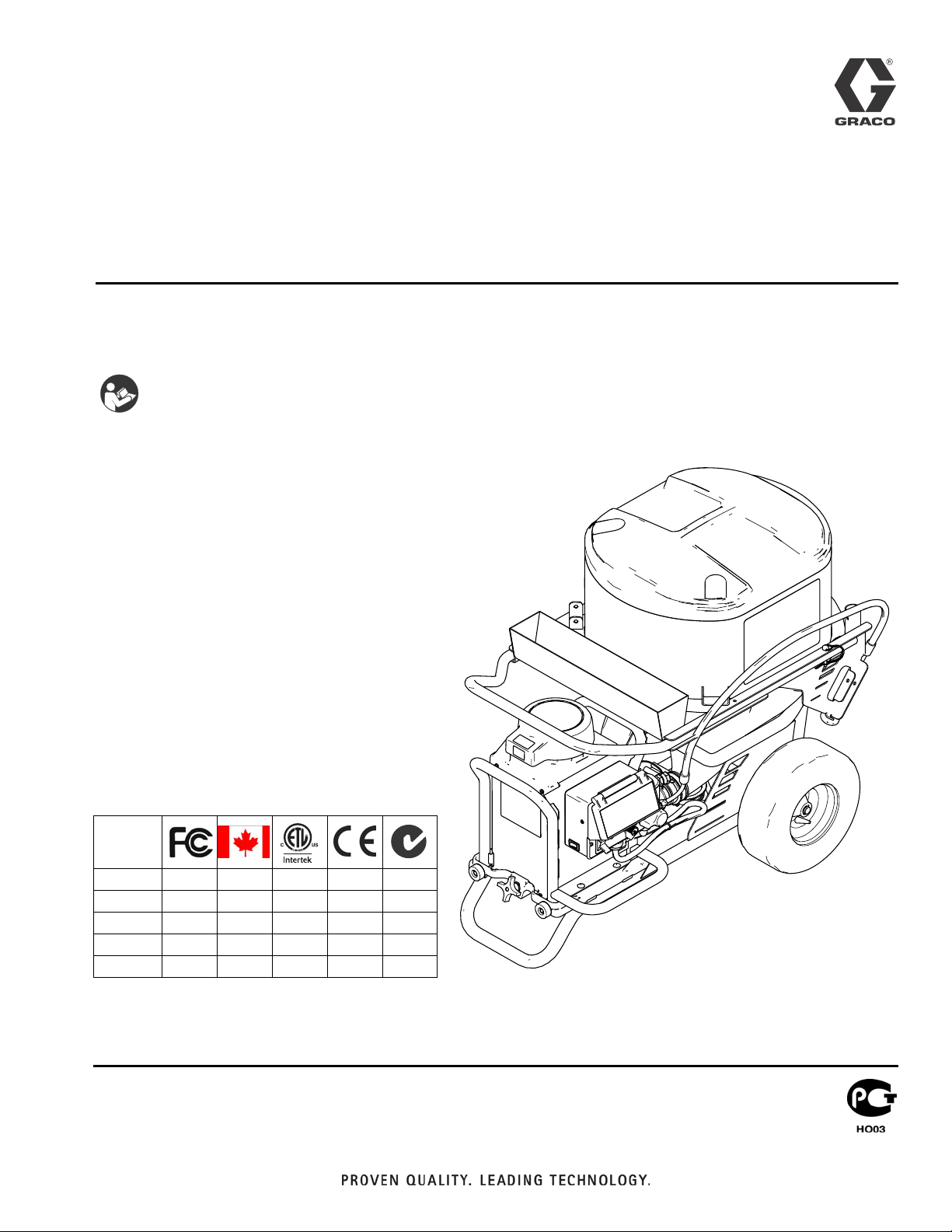
Repair
Drywall Feed Pump
U.S. Patents Pending: 61/315,288; 61/315/322; 61/316,013; 61/316,010
- For water-based materials only -
- Not for use in explosive atmospheres -
- Not for use with quick-set materials -
READ ALL WARNINGS AND INSTRUCTIONS
Read all warnings and instructions in this manual.
Save these instructions.
Maximum Working Pressure 2500 psi (17.2 MPa, 172 bar)
Model 257100: 120V NA ETL Listed
Model 258906: 240V Euro Multicord
Model 258907: 110V UK, CE
Model 262288: 120V NA
Model 262300: 240V Euro CE Cord
3A0246C
ENG
Agency Approvals:
257100 ✓✓✓
258906 ✓✓
258907 ✓
262288 ✓✓
262300 ✓✓
ti14873a
Page 2
Warning
Warning
The following warnings are for the setup, use, grounding, maintenance, and repair of this equipment. The exclamation point
symbol alerts you to a general warning and the hazard symbols refer to procedure-specific risks. When these symbols appear
in the body of this manual, refer back to these Warnings. Product-specific hazard symbols and warnings not covered in this section may appear throughout the body of this manual where applicable.
WARNING
WARNINGWARNINGWARNING
ELECTRIC SHOCK HAZARD
This equipment must be grounded. Improper grounding, setup, or usage of the system can cause electric shock.
• Turn off and disconnect power cord before servicing equipment.
• Use only grounded electrical outlets.
• Use only 3-wire extension cords.
• Ensure ground prongs are intact on power and extension cords.
• Do not expose to rain. Store indoors.
SKIN INJECTION HAZARD
High-pressure fluid from dispensing device, hose leaks, or ruptured components will pierce skin. This may look like
just a cut, but it is a serious injury that can result in amputation. Get immediate surgical treatment.
• Engage trigger lock when not dispensing.
• Do not point dispensing device at anyone or at any part of the body.
• Do not put your hand over the fluid outlet.
• Do not stop or deflect leaks with your hand, body, glove, or rag.
• Follow the Pressure Relief Procedure when you stop dispensing and before cleaning, checking, or servicing
equipment.
• Tighten all fluid connections before operating the equipment.
• Check hoses and couplings daily. Replace worn or damaged parts immediately.
FIRE AND EXPLOSION HAZARD
Flammable fumes, such as solvent and paint fumes, in work area can ignite or explode. To help prevent fire and
explosion:
• Do not dispense flammable or combustible materials near an open flame or sources of ignition such as cigarettes,
motors, and electrical equipment.
• Material or solvent flowing through the equipment is able to result in static electricity. Static electricity creates a
risk of fire or explosion in the presence of material or solvent fumes. All parts of the system, including the pump,
hose assembly, dispenser, and objects in and around the work area shall be properly grounded to protect against
static discharge and sparks. Use Graco conductive or grounded high-pressure airless material hoses.
• Verify that all containers and collection systems are grounded to prevent static discharge.
• Connect to a grounded outlet and use grounded extensions cords. Do not use a 3-to-2 adapter.
• Do not use a material or a solvent containing halogenated hydrocarbons.
• Keep work area well-ventilated. Keep a good supply of fresh air moving through the area. Keep pump assembly in
a well ventilated area.
• Do not smoke in the work area.
• Do not operate light switches, engines, or similar spark producing products in the work area.
• Keep area clean and free of material or solvent containers, rags, and other flammable materials.
• Know the contents of the materials and solvents being dispensed. Read all Material Safety Data Sheets (MSDS)
and container labels provided with the materials and solvents. Follow the material and solvents manufacturer’s
safety instructions.
• Fire extinguisher equipment shall be present and working.
• Drywall feed pump generates sparks. When flammable liquid is used in or near the drywall feed pump or for
flushing or cleaning, keep unit at least 20 feet (6 m) away from explosive vapors.
2 3A0246C
Page 3
Warning
WARNING
WARNINGWARNINGWARNING
MOVING PARTS HAZARD
Moving parts can pinch, cut or amputate fingers and other body parts.
• Keep clear of moving parts.
• Do not operate equipment with protective guards or covers removed.
• Pressurized equipment can start without warning. Before checking, moving, or servicing equipment, follow the
Pressure Relief Procedure and disconnect all power sources.
EQUIPMENT MISUSE HAZARD
Misuse can cause death or serious injury.
• Always wear appropriate gloves, eye protection, and a respirator or mask when dispensing.
• Do not operate or dispense near children. Keep children away from equipment at all times.
• Do not overreach or stand on an unstable support. Keep effective footing and balance at all times.
• Stay alert and watch what you are doing.
• Do not leave the unit energized or under pressure while unattended. When the unit is not in use, turn off the unit and
follow the Pressure Relief Procedure for turning off the unit.
• Do not operate the unit when fatigued or under the influence of drugs or alcohol.
• Do not kink or over-bend the hose.
• Do not expose the hose to temperatures or to pressures in excess of those specified by Graco.
• Do not use the hose as a strength member to pull or lift the equipment.
PRESSURIZED ALUMINUM PARTS HAZARD
Use of fluids that are incompatible with aluminum in pressurized equipment can cause serious chemical reaction and
equipment rupture. Failure to follow this warning can result in death, serious injury, or property damage.
• Do not use 1,1,1-trichloroethane, methylene chloride, other halogenated hydrocarbon solvents or fluids containing such
solvents.
• Many other fluids may contain chemicals that can react with aluminum. Contact your material supplier for compatibility.
PERSONAL PROTECTIVE EQUIPMENT
You must wear appropriate protective equipment when operating, servicing, or when in the operating area of the equipment
to help protect you from serious injury, including eye injury, hearing loss, inhalation of toxic fumes, and burns. This
equipment includes but is not limited to:
• Protective eyewear, and hearing protection.
• Respirators, protective clothing, and gloves as recommended by the fluid and solvent manufacturer.
3A0246C 3
Page 4
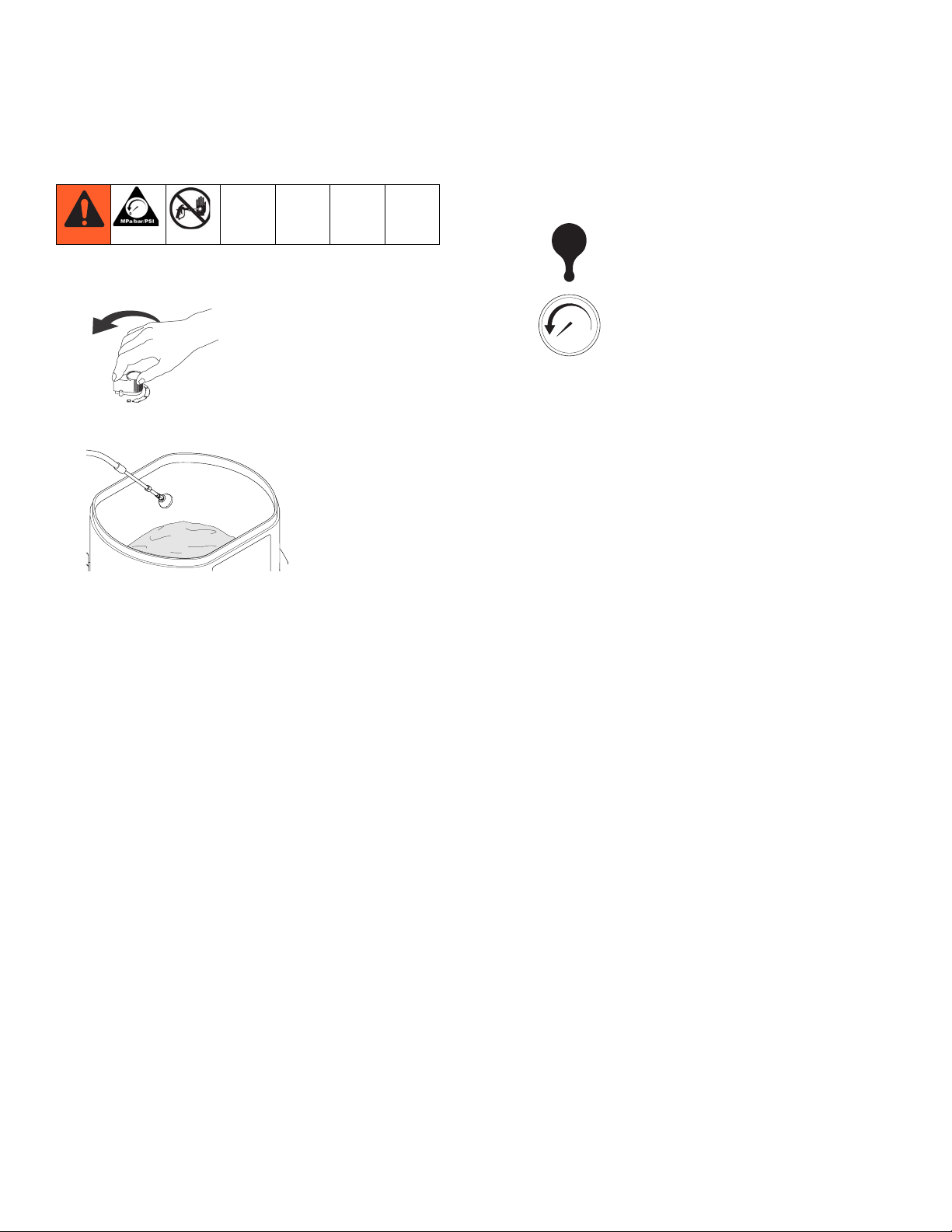
Pressure Relief Procedure
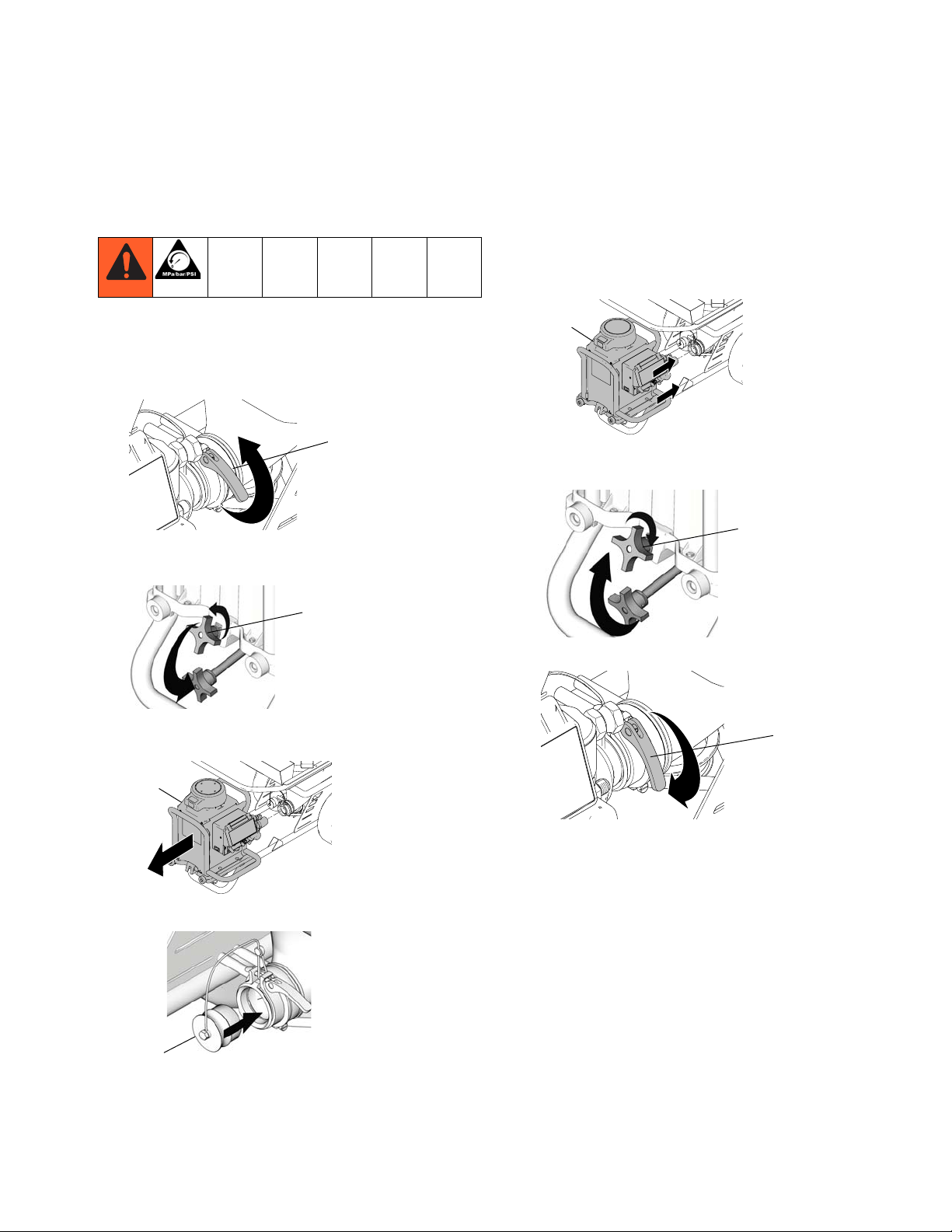
Pressure Relief Procedure
1. Turn flow control knob to fully counterclockwise to
OFF position.
3. Turn prime valve handle to PRESSURE RELIEF
position.
ti8793a
2. Place deflector in hopper or suitable container.
ti14876a
bar/psi
ti15614a
4. Display will read “----” when all pressure is relieved.
4 3A0246C
Page 5
Drive and Bearing Housing
Drive and Bearing Housing
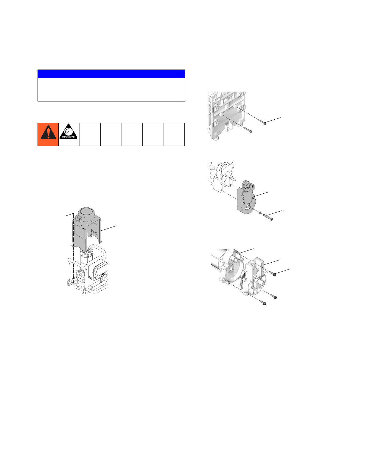
NOTICE
Do not drop gear cluster (17a) when removing drive
housing (5a). Gear cluster may stay engaged in motor
front end bell or drive housing.
Removal
1. Perform Pressure Relief Procedure, page 4.
2. Remove Power Module, see page 7.
3. Remove Pump, page 8.
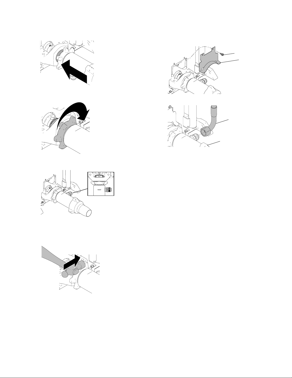
4. Remove four screws (40) and lift motor shroud (98)
off of motor.
40
98
6. Remove two screws (5b) from underneath motor
base plate. Lift and remove motor/pump assembly
from power module.
5b
ti11734a
7. Loosen four screws (19) on pump housing, and
remove bearing housing (9) from motor.
9
ti15630a
19
8. Remove three screws (5c) on motor (8a). Remove
motor (8a) from drive housing (5a).
8a
ti15624a
5. Disconnect three wire harnesses (see Wiring
Diagrams, pages 34-36).
5a
5c
ti11735a
3A0246C 5
Page 6
Drive and Bearing Housing
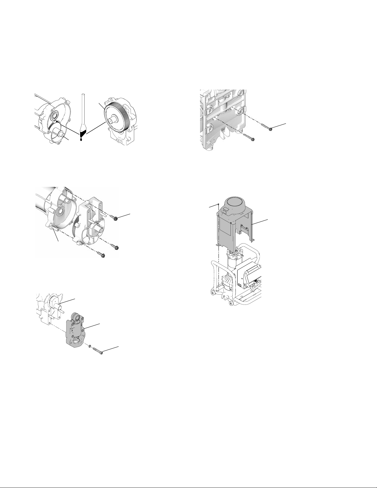
Installation
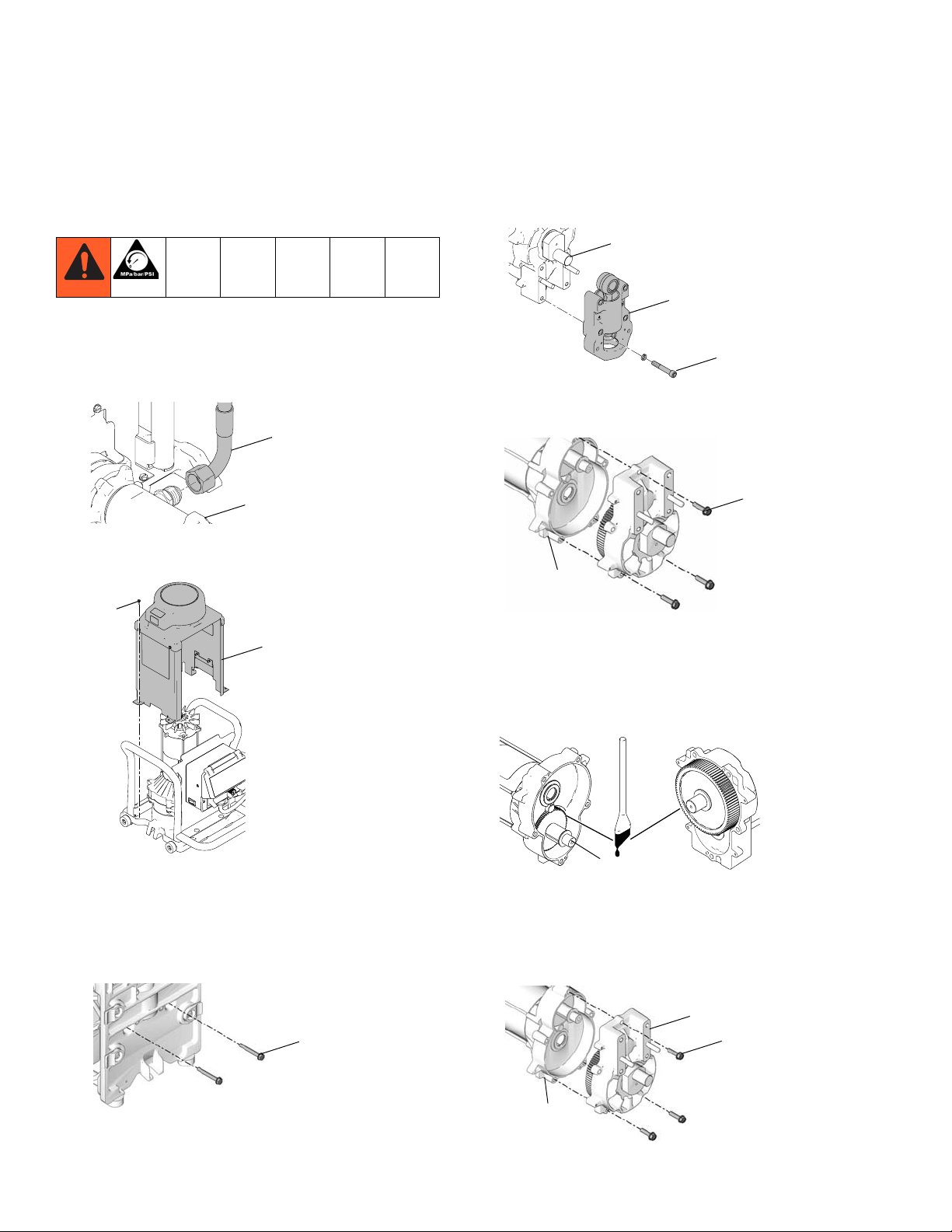
1. Apply brown lithium grease supplied with drive
housing kit (5) to gear cluster (17a) and inside of
motor cavity.
5a
17a
ti15629a
2. Align orientation tab on gear housing with slot on
motor and slide gears into motor.
3. Replace and tighten three screws (5c) on motor
(8a). Torque to 200-220 in-lb.
5c
8a
ti11735a
5. Replace motor/pump assembly into pump module.
Replace and tighten two screws (5b) underneath
motor base plate. Torque to 200 - 220 in-lb.
5b
ti11734a
6. Reconnect three wire harnesses (see Wiring
Diagrams, pages 34-36).
7. Replace motor shroud (98) and tighten four screws
(40). Torque to 30-34 in-lb.
40
98
4. Attach bearing housing (9) to gear housing (5a)
(slowly turn motor fan by hand to align gear into
pump connecting rod). Torque four bearing housing
screws (19) to 25-30 ft-lb.
5a
9
ti15630a
19
ti15624a
8. Replace Pump, page 8.
9. Replace Power Module, see page 7.
6 3A0246C
Page 7
Power Module
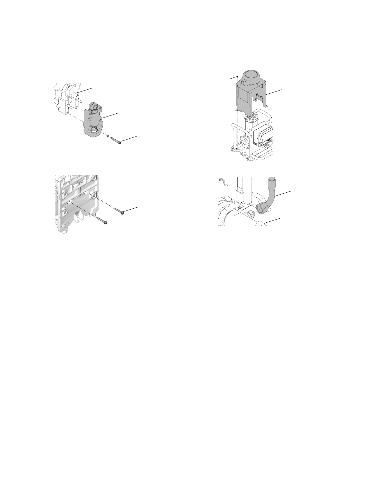
Power Module
Removal
1. Perform Pressure Relief Procedure, see page 4.
Unplug power cord.
2. Release hopper adapter clamp (158).
158
ti15684a
3. Loosen rod clamp knob (112) on front of pump module and push rod down.
112
Installation
1. Remove hopper plug (117) if installed.
2. Replace power (153) module and insert pump outlet
into hopper inlet.
153
ti15625a
3. Pull rod clamp up and tighten knob (112) on front of
pump module.
112
ti11678a
ti11675a
4. Lift and pull power module (153) off of unit.
NOTE: Power module weighs approximately 85 lb.
153
ti15623a
5. Install hopper plug (117) if needed.
117
ti15623a
4. Fasten hopper adapter clamp (158).
158
ti15683a
3A0246C 7
Page 8
Pump
Pump
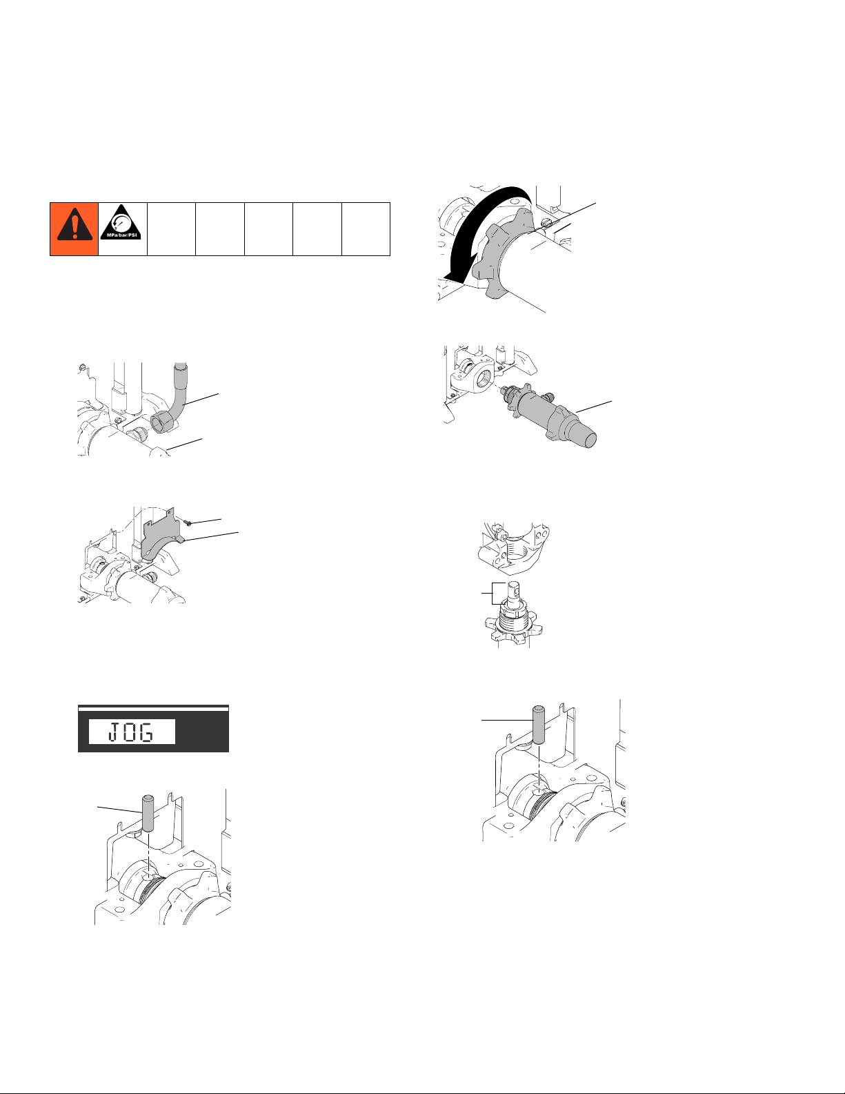
Removal
1. Perform Pressure Relief Procedure, see page 4.
2. Remove Power Module, see page 7.
3. Disconnect material hose (79) from pump (18a).
79
18a
ti15616a
4. Loosen two screws (40) and remove pump rod
shield (48).
40
48
7. Use hammer to loosen pump retaining nut (22).
22
ti15615a
8. Unscrew and remove pump (18a) from module.
18a
ti15618a
Installation
1. Extend pump piston rod 1.5 in.
ti15619a
5. Turn flow control knob to a very low setting and turn
prime valve handle to TOOL FILL position (JOG
mode will appear in display). Use ON/OFF switch or
turn control knob OFF to stop pump when pin is
visible.
ti15620a
6. Use screwdriver to press pin (7b) out of pump.
7b
ti15617a
NOTE: Pin should be removed by pressing the pin
out through the bottom side of the pump. Make sure
to control the pump pin when removing so that it
does not fall into the pump module.
1.5 in.
ti7171a
2. Install pump pin (7b). Verify retaining spring is in
groove of connecting rod.
7b
ti13093a
NOTE: Pin should be installed from the top side of the
pump. Make sure to control the pump pin when installing
so that it does not fall into the pump module.
8 3A0246C
Page 9
Pump
3. Push pump up until pump threads engage.
ti15924a
4. Screw in pump until threads are flush with drive
housing opening.
ti15621a
5. Align pump outlet to right side so that hose can be
reassembled.
7. Replace pump rod shield (48) and torque two
screws (40) to 30 - 34 in-lb.
40
48
ti15619a
8. Reconnect material hose (79) to pump (18a).
79
18a
ti15616a
9. Replace Power Module, see page 7.
ti15923a
6. Screw jam nut up toward drive housing until nut
stops. Tighten jam nut by hand, then tap 1/8
to 1/4 turn with a 20 oz. (maximum) hammer to
approximately 75± 5 ft-lb (102 N•m).
ti15925a
3A0246C 9
Page 10
Motor
Motor
Removal
1. Perform Pressure Relief Procedure, see page 4.
2. Remove Power Module, see page 7.
3. Disconnect material hose (79) from pump (18a).
79
18a
ti15616a
4. Remove four screws (40) and lift motor shroud (98)
off of motor.
40
98
7. Loosen four screws (19) on bearing housing (9),
and remove from gear housing.
5a
9
ti15630a
19
8. Remove three screws (5c) on motor (8a). Remove
motor from gear housing.
5c
8a
ti11735a
Installation
ti15624a
5. Disconnect three wire harnesses (see Wiring
Diagrams, pages 34-36).
6. Remove two screws (5b) from underneath motor
base plate. Lift and remove motor/pump assembly
from pump module.
5b
ti11734a
1. Apply brown lithium grease supplied with motor
repair kit (8) to gear cluster (17a) and inside of
motor cavity.
17a
ti15629a
2. Align orientation tab on gear housing with slot on
motor and slide gears into motor.
3. Replace three screws (5c) on motor (8a). Torque to
200-220 in-lb.
5a
5c
8a
ti11735a
10 3A0246C
Page 11
Motor
4. Attach bearing housing (9) to gear housing (5a)
(slowly turn motor fan by hand to align gear into
pump connecting rod). Torque four bearing housing
screws (19) to 25-30 ft-lb.
5a
9
ti15630a
19
5. Replace motor/pump assembly into pump module.
Replace and torque two screws (5b) underneath
motor base plate to 200 - 220 in-lb.
5b
ti11734a
6. Reconnect three wire harnesses (see Wiring
Diagrams, pages 34-36).
7. Replace motor shroud (98) and torque four screws
(40) to 30 - 34 in-lb.
40
98
ti15624a
8. Reconnect material hose (79) to pump (18a).
79
18a
ti15616a
9. Replace Power Module, see page 7.
3A0246C 11
Page 12
Motor Control Board
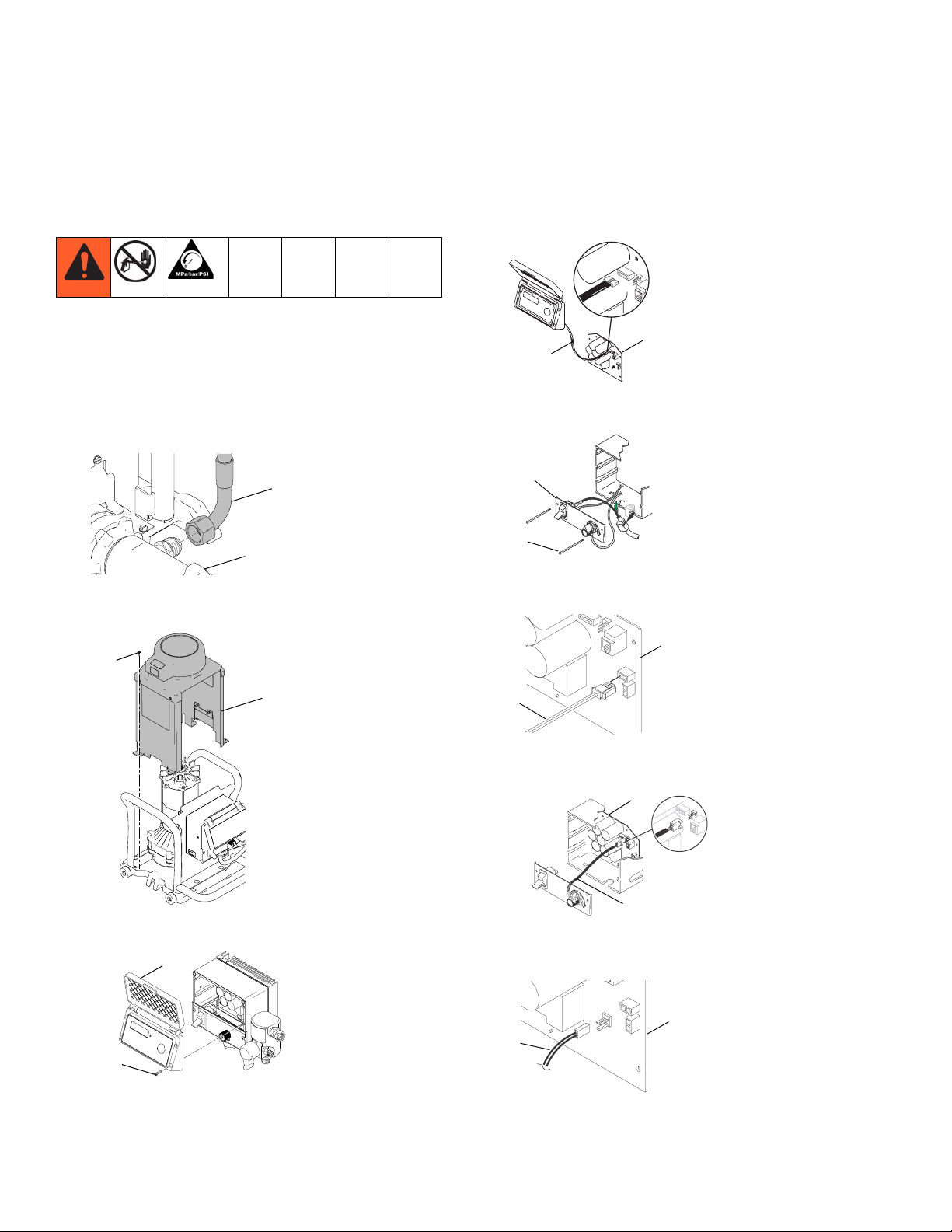
Motor Control Board
Removal
120V Models:
1. Perform Pressure Relief Procedure, see page 4.
Wait 5 minutes before servicing.
2. Remove Power Module, see page 7.
3. Disconnect material hose (79) from pump (18a).
79
18a
ti15616a
4. Remove four screws (40) and lift motor shroud (98)
off of motor.
40
6. Disconnect display connector (A) from motor control
board (24) and remove display.
ti13569a
24
A
7. Remove bottom two screws (61) and remove control
panel (37).
37
61
ti15795a
8. Disconnect Prime/Tool Fill/Recirculate reed switch
connector (E) from motor control board (24).
24
98
ti15624a
5. Remove four screws (33b) and display cover (33k).
33k
33b
ti15786a
E
ti13572a
9. Disconnect potentiometer connector (C) from motor
control board (24).
24
ti15791a
C
10. Disconnect 15/20A switch connector (X) from motor
control board (24).
24
X
ti15850a
12 3A0246C
Page 13

Motor Control Board
11. Disconnect white power cord conductor (D) from
motor control board (24).
24
ti15851a
D
12. Disconnect black power lead (J) on motor control
board (24) from ON/OFF switch.
J
ti15849a
13. Remove ground screw (58) from motor control
board/heat sink assembly.
16. Disconnect three motor connectors from motor control board to motor.
ti15847a
17. Remove two screws (83) holding motor control
board /heat sink assembly to power module frame.
Remove motor control board/heat sink assembly.
83
ti15845a
18. Remove six outer screws, two inner screws, and
remove control board (24) from heat sink.
58
ti15846a
14. Remove two top screws (61) and control box (3).
61
3
ti15912a
15. Disconnect transducer connector from motor control
board (24).
ti12999a
24
ti15844a
24
3A0246C 13
Page 14

Motor Control Board
110 UK and 240V Models:
1. Perform Pressure Relief Procedure, see page 4.
Wait 5 minutes before servicing.
2. Remove Power Module, see page 7.
3. Disconnect material hose (79) from pump (18a).
79
18a
ti15616a
4. Remove four screws (40) and lift motor shroud (98)
off of motor.
40
98
7. Remove bottom two screws (61) control panel (37).
37
61
ti15795a
8. Disconnect Prime/Tool Fill/Recirculate reed switch
connector (E) from motor control board (24).
24
E
ti13572a
9. Disconnect potentiometer connector (C) from motor
control board (24).
24
ti15624a
5. Remove four screws (33b) and display cover (33k).
33k
33b
ti15786a
6. Disconnect display from motor control board (24)
and remove display.
24
ti13569a
ti15791a
C
10. Disconnect black power lead (G) from motor control
board to filter board. Disconnect blue power lead (B)
from motor control board to filter board.
G
B
ti15848a
11. Remove ground screw (58) from motor control
board/heat sink assembly.
58
ti15846a
14 3A0246C
Page 15

Motor Control Board
12. Remove top two screws (61) and control box (3).
61
3
ti15912a
13. Disconnect transducer connector from motor control
board (24).
ti12999a
24
14. Disconnect three motor connectors from motor control board to motor.
15. Remove two screws (83) holding motor control
board / heat sink assembly to power module frame.
Remove motor control board/heat sink assembly.
83
ti15845a
16. Remove six outer screws, two inner screws, and
remove control board (24) from heat sink.
24
ti15844a
ti15847a
3A0246C 15
Page 16

Motor Control Board
Installation
120V Models:
1. Use acetone or equivalent cleaner to thoroughly
remove thermal paste from pockets on heat sink.
ti14695a
2. Apply new thermal paste into both pockets of heat
sink.
ti14693a
3. Replace two inner screws and washers to control
board and torque to 17 in-lb.
5. Connect motor control board lead connectors (F) to
leads from motor. Insert grommet in heat sink baffle.
Use zip tie or electrical tape (Z) to hold grommet
together on grommet end on the motor side of the
heat sink.
Z
F
ti15852a
6. Assemble gasket (94) to heat sink assembly.
94
ti15911a
7. Assemble two screws (83) to hold motor control
board/ heat sink assembly to power module frame.
Torque to 35-45 in-lb.
ti15926a
4. Replace six outer screws to control board and
torque to 11 in-lb.
ti14697a
NOTE: SW1 position setting does not matter.
83
ti15845a
8. Assemble ground screw (58) to heat sink. Torque to
30-34 in-lb.
58
ti15846a
9. Assemble control box enclosure (3) to power module and tighten two screws (61). Torque to 30-35
in-lb.
61
3
ti15912a
16 3A0246C
Page 17

Motor Control Board
10. Connect black power lead (J) on motor control
board to ON/OFF switch.
J
ti15849a
11. Connect white power cord conductor (D) to motor
control board (24).
24
ti15851a
D
12. Connect 15/20A switch connector (X) to motor control board (24).
15. Replace control panel (37) and tighten bottom two
screws (61). Torque to 30-35 in-lb.
37
61
ti15795a
16. Connect display connector to motor control board
(24).
ti13569a
24
17. Assemble display cover (33k). Spring tabs on noise
shield need to be assembled to the inside of the
control box enclosure. Torque screws (33b) to
30-35 in-lb.
33k
24
X
ti15850a
13. Connect potentiometer connector (C) to motor control board (24).
24
ti15791a
C
14. Connect Prime/Tool Fill/Recirculate reed switch connector (E) to motor control board (24).
24
E
ti13572a
33b
ti15786a
18. Remove four screws (40) and lift motor shroud (98)
off of motor.
40
98
ti15624a
19. Disconnect material hose (79) from pump (18a).
79
18a
ti15616a
20. Replace Power Module, see page 7.
3A0246C 17
Page 18

Motor Control Board
110 UK and 240V Models:
1. Use acetone or equivalent cleaner to thoroughly
remove thermal paste from pockets on heat sink.
ti14695a
2. Apply new thermal paste into both pockets of heat
sink.
ti14693a
3. Replace two inner screws and washers to control
board and torque to 17 in-lb.
6. Assemble gasket (94) to heat sink assembly.
94
ti15911a
7. Assemble two screws (83) to hold motor control
board/ heat sink assembly to power module frame.
Torque to 35-45 in-lb.
83
ti15845a
8. Assemble ground screw (58) to heat sink. Torque to
30-34 in-lb.
ti15926a
4. Replace six outer screws to control board and
torque to 11 in-lb.
ti14697a
NOTE: SW1 position setting does not matter.
5. Connect motor control board lead connectors (F) to
leads from motor. Insert grommet in heat sink baffle.
Use zip tie or electrical tape (Z) to hold grommet
together on grommet end on the motor side of the
heat sink.
Z
F
58
ti15846a
9. Assemble control box enclosure (3) to power module using two top screws (61). Torque to 30-35 in-lb.
61
3
ti15912a
10. Connect blue (B) and black (G) power leads from
motor control board (24) to filter board.
G
B
ti15848a
ti15852a
18 3A0246C
Page 19

Motor Control Board
11. Connect potentiometer connector (C) to motor control board (24).
24
ti15791a
C
12. Connect Prime/Tool Fill/Recirculate reed switch connector (E) to motor control board (24).
24
E
ti13572a
13. Replace control panel (37) and tighten bottom two
screws (61). Torque to 30-35 in-lb.
15. Assemble display cover (33k). Spring tabs on noise
shield need to be assembled to the inside of the
control box enclosure. Torque screws to 30-35 in-lb.
33k
ti15786a
16. Replace motor shroud (98) and torque four screws
(40) to 30 - 34 in-lb.
40
98
37
ti15795a
61
14. Connect display connector to motor control board
(24).
ti13569a
24
ti15624a
17. Reconnect material hose (79) to pump (18a).
79
18a
ti15616a
18. Replace Power Module, see page 7.
3A0246C 19
Page 20

Prime Valve Handle
Prime Valve Handle
Removal
1. Perform Pressure Relief Procedure, see page 4.
Wait 5 minutes before servicing.
2. Use 3/32 in. punch and hammer to tap out handle
pin (72c) (pliers may be required to pull out handle
pin). Pull off handle (72a) and base (72b).
3. Use crescent wrench to unscrew prime valve (71).
NOTE: Make sure that the seat and gasket are
removed from the manifold.
4. Clear out any material that is lodged in valve (71) or
manifold (70).
Installation
1. Tighten prime valve (71) into manifold (70). Use
thread sealant on housing threads and torque to
190 to 210 in-lb.
2. Install prime valve base (72b). Pin in base must
align with hole in manifold (70).
3. Orient hole in prime valve stem (71) vertically.
4. Place prime valve handle (72a) over prime valve
base (72b) with handle in “apply” mode. Align hole
in handle (72a) w/hole in prime valve stem (71).
5. Use hammer to tap prime valve handle pin (72c)
back into place.
71
72c
70
72a
72b
20 3A0246C
ti15633a
Page 21

Pressure Transducer
Pressure Transducer
Removal
1. Perform Pressure Relief Procedure, see page 4.
Wait 5 minutes before servicing.
2. Remove four screws (33b) and cover (33k).
33k
33b
3. Disconnect transducer connector (E) from motor
control board (24).
24
E
ti15786a
5. Remove four screws (61) and control box (3). Allow
control panel (37) to hang down freely.
3
37
61
ti15797a
61
ti15795a
6. Remove grommet (23) from control box (3).
23
ti15785a
3
7. Remove transducer (39) and o-ring (50) from manifold (70). Remove grommet (23) from transducer
and save for reuse.
70
23
39
50
ti12999a
4. Disconnect potentiometer connector (D) and reed
switch connector (87) from motor control board (24).
D
24
87
ti15792a
ti15788a
Installation
1. Install o-ring (50) and transducer (39) in manifold
(70). Torque to 35-45 ft-lb (47-61 N•m). Install grommet onto transducer (39) and transducer into control
box (3).
70
23
39
50
ti15783a
ti15793a
3
3A0246C 21
Page 22

Pressure Transducer
2. Connect transducer connector (E) and reed switch
connector to control board (24).
24
E
ti12999a
3. Install control box (3) and control panel (37) with
four screws (61). Torque to 30 - 35 in-lb.
3
37
61
ti15797a
61
ti15795a
5. Connect display connector (A) to motor control
board (24).
ti13569a
24
A
6. Install cover (33k) with four screws (33b). Torque to
30-35 in-lb. Make sure tabs on noise shield are
routed inside the control box when assembling.
4. Connect potentiometer connector (D) and reed
switch connector (87) to control board (24).
D
24
87
ti15792a
33k
ti15786a
33b
22 3A0246C
Page 23

Flow Control Adjust Potentiometer
Flow Control Adjust
Potentiometer
Removal
1. Perform Pressure Relief Procedure, see page 4.
Wait 5 minutes before servicing.
2. Remove four screws (33b) and cover (33k).
ti15786a
33k
33b
3. Remove bottom two screws (61) and remove control
panel (37).
37
6. Remove gasket (56), nut, spacer (88) and potentiometer (55) from control panel (37).
ti15794a
56
55
88
37
Installation
1. Install gasket (56), nut, spacer (88) and potentiometer (55) on control panel (37). Torque nut to 30-35
in-lb (3.25-4.0 N•m).
55
ti15794a
56
2. Install control knob (42): Check control knob alignment to potentiometer shaft. Turn shaft fully clockwise and attach knob in full ON position with a hex
wrench. Make sure set screw is tightened flat
against potentiometer shaft.
88
37
61
ti15795a
4. Disconnect potentiometer connector (D) from motor
control board (24).
24
ti15791a
D
5. Use hex wrench to remove control knob (42).
42
ti7258a
42
ti13338a
3. Connect potentiometer connector (D) to motor control board (24).
24
D
ti15791a
3A0246C 23
Page 24

Flow Control Adjust Potentiometer
4. Replace control panel (37) and tighten bottom two
screws (61). Torque to 30-35 in-lb.
37
61
ti15795a
5. Connect display connector (A) to motor control
board (24).
ti13569a
24
A
6. Install cover (33k) with four screws (33b). Torque to
30-35 in-lb. Make sure tabs on noise shield are
routed inside the control box when assembling.
33k
33b
ti15786a
24 3A0246C
Page 25

Prime/Tool Fill/Recirculation Reed Switch
Prime/Tool Fill/Recirculation Reed Switch
Removal
1. Perform Pressure Relief Procedure, see page 4.
Wait 5 minutes before servicing.
2. Remove four screws (33b) and remove display
cover (33k).
33k
ti15786a
33b
3. Remove bottom two screws (61) and remove control
panel (37).
Installation
1. Apply thread sealant to end of reed switch (87).
Hand-tighten reed switch until it is tight against
control panel (37).
37
87
ti13574a
2. Add thread sealant and tighten jam nut against
threaded bus.
ti13576a
3. Connect reed switch (87) to control board (24).
24
37
61
ti15795a
4. Unplug reed switch (87) from control board.
87
ti13572a
5. Unscrew reed switch (87) from control panel (37).
37
87
ti13573a
87
ti13572a
4. Replace control panel (37) and tighten bottom two
screws (61). Torque to 30-35 in-lb.
37
61
ti15795a
5. Replace display cover (33k) and torque four screws
(33b) to 30-35 in-lb.
33k
33b
ti15786a
NOTE: Make sure noise shield tabs are routed to the
inside of the control box when assembling.
3A0246C 25
Page 26

Digital Display
Digital Display
Removal
1. Turn off unit. Wait 5 minutes before servicing.
2. Remove four screws (33b) and remove display
cover (33k).
33k
ti15786a
33b
3. Unplug display board connector from motor control
board (24).
Installation
1. Plug display board connector (A) into motor control
board (24).
ti13569a
A
2. Replace display cover (33k) and torque four screws
(33b) to 30-35 in-lb.
24
ti13569a
33k
33b
24
A
NOTE: Make sure noise shield tabs are routed to the
inside of the control box when assembling.
ti15786a
26 3A0246C
Page 27

Inline Valve
Inline Valve
Changing the Needle
Removal
NOTE: Needle (404b), housing/seat (404c), and o-ring
(404a) must be replaced together. They are included in
repair kit 24F263.
1. Perform Pressure Relief Procedure, see page 4.
2. Squeeze trigger while unscrewing housing/seat
(404c) and o-ring (404a).
404c
ti15626a
3. Remove trigger stop (420) with hex wrench.
404a
ti15810a
404b
5. Tap rear of inline valve with a plastic mallet and
punch to push needle assembly (404b) out through
front of housing (401).
ti15809a
404b
401
Installation
1. Guide threaded end of needle assembly (404b) into
front of housing (401).
ti15804a
404b
2. Install bracket (413) and locknut (414) loosely on
threaded end of needle (404b). Squeeze trigger to
pull needle assembly into housing (401).
401
420
ti15806a
413
414
ti15862a
3. Squeeze trigger while installing o-ring (404a) and
4. Remove locknut (414) and bracket (413).
housing/seat (404c). Torque housing/seat to 26-32
ft-lb (35-43 N•m).
404a
t15805Xa
404b
ti15811a
413
404c
414
ti15626a
4. Adjust needle before using inline valve.
3A0246C 27
Page 28
Inline Valve
Needle Adjustment
1. Engage inline valve (135) with safety latch. Hold
inline valve with nozzle straight up.
2. Hold your finger against trigger (410) with light pressure. Use a 5/16 open-ended wrench to turn locknut
(414) clockwise until you feel trigger lift slightly.
3. Turn locknut (414) 3/4 turn counter-clockwise.
4. Connect fluid hose. Prime the system. Trigger inline
valve (135) and release it. The fluid flow should stop
immediately. Engage safety latch and try to trigger
inline valve. No fluid should flow. If the inline valve
fails either test, relieve pressure, disconnect hose
and readjust needle.
5. Install trigger stop (420) when needle has been
properly adjusted.
ti15862a
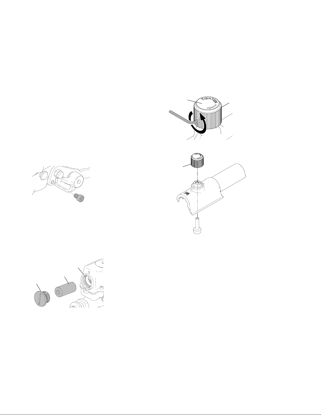
Box Slide Control
Use Brake Assembly Repair Kit 24F261
Removal
1. Remove set screw from brake knob (518b).
518a
2. Unthread brake knob (518b) from assembly.
518b
518b
ti15863a
Replacing the Battery
Removal
1. Unscrew battery cap (425a) from housing (411).
Remove battery and discard.
411
426
425a
ti15812a
Installation
1. Install battery (426) in housing (411) and screw in
battery cap (425a).
NOTE: Make sure o-ring (425b) is in place when
installing the battery cap (425a).
ti15865a
Installation
1. Thread brake knob (518b) onto assembly
2. Apply label (518a).
3. Torque set screw to 15-20 in-lb.
28 3A0246C
Page 29

Parts
Parts
112
160
152
113
114
116
115
163
162
156
138
161
111
146
147
119
126
155
148
117
154
118
155
154
157
171
170
158
153
127
141
128
139
129
Ref. Part Description Qty.
111 120211 RING, retaining, e-ring 2
112 15C799 ROD, clamp 1
113 104430 PIN, cotter 1
114 15C797 BRACKET, swivel 1
115 101566 NUT, lock 1
116 100004 SCREW, cap, hex HD 1
117 15D306 PLUG, adapter, hopper, texture 1
118 121458 TIE, lanyard 1
119 100333 SCREW, cap, hex HD 1
126 16C298 FILTER, hopper 1
127 257133 HOSE, cpld, 1/2 in. mxf 50 ft 1
128 223756 HOSE, cpld, 1/4 in. x 15 ft 1
129 24D166 SWIVEL, Z, complete 1
135 24F538 VALVE, inline, assembly 1
137 24E958 KIT, drain, hose 1
138 122267 WHEEL, foam 2
139 150287 COUPLING 1
141 162449 FITTING, nipple, reducing 1
146 16C794 SPACER, .75 OD X .4 ID X .625 1
137
135
ti15642a
180
Ref. Part Description Qty.
147 278204 CLIP, drain line 1
148 112785 SCREW, hex HD, flanged 1
152 15R633 FRAME, painted, TMAX 1
153 257047 MODULE, power, ETL listed 1
258890 MODULE, power, CE listed 1
258893 MODULE, power, UK CE listed 1
262289 MODULE, power, 120V 1
262299 MODULE, power, CE Cord 1
154 289668 HOPPER, assembly 1
155 16D307 LABEL, brand, drywall us, hopper 2
156 116038 WASHER, wave spring 2
157 121308 PLUG, expanding 1
158 234188 CLAMP, quick release 1
160 15R639 HANDLE, TMAX 1
161 112958 NUT, hex, flanged 1
162 121313 PIN, locking, 1/4 in. 2
163 156306 WASHER, flat 2
170 15R609 FITTING, hopper, adapter 1
171 102905 CLAMP, hose 1
180 24F463 KIT, control, box slide 1
3A0246C 29
Page 30

Parts
Pump Module Parts
102
99
105
40
21
8c
8b
101
24
58
94
29
83
104
84
ti15643a
23
75
39
25
74
50
79
70
4040
48
98
71
92
72b
36
46b
78
80
72c
72a
8a
17a
17b
5d
5a
5c
7c
7a
17c17c
79
18b
18a
7b
22
9
20
61
19
94
87
88
81
61
3
46c
108
32
4
6
28
109
110
3 ref
30 3A0246C
10
5b
182
43
181 183
54
46a
27
41
55
37
38
56
42
33e
33a
33c
33j
33m
33h
33b
33d
33k
Page 31

Pump Module Parts List
Parts
Ref. Part Description Qty.
3 15G700 BOX, control 1
15D431 BOX, control, CE and UK 1
4 277657 GUIDE, base 4
5 24E959 KIT, housing, drive 1
5a HOUSING, drive 1
5b 120981 SCREW, mach, hex washer HD 2
5c 15C753 SCREW, mach, hex wash HD 3
5d 116192 WASHER, thrust 1
6 100023 WASHER, flat 4
7 287720 KIT, rod, connecting 1
7a ROD, connecting 1
7b 15F856 PIN, pump 1
7c 119778 SPRING, retaining 1
8 24D362 KIT, motor, electric 1
8a MOTOR, electric 1
8b 15V577 FAN, motor 1
8c 122347 RING, retaining, external 1
9 240724 HOUSING, bearing 1
10 113817 BUMPER 2
17 287290 KIT, gear, combination 1
17a GEAR, combo 1
17b 114699 WASHER, thrust 1
17c 114672 WASHER, thrust 2
18 24E957 KIT, pump, displacement 1
18a PUMP, displacement 1
18b 15Y925 FITTING, 5/8 JIC / 1/2 NPT 1
19 114666 SCREW, cap, socket head 4
20 106115 WASHER, lock (hi-collar) 4
21 16D622 SHIELD, assy, painted 1
22 193031 NUT, retaining 1
23 15D033 GROMMET, transducer 1
24 258843† CONTROL, board, drywall feed 1
258889* CONTROL, board, drywall (240V) 1
25 100016 WASHER, lock 4
27 116171 BUSHING, strain relief 1
28 112746 NUT, lock, nylon, thin pattern 4
29 107129 BOLT, round head 4
32 260215 SCREW, hex HD 2
33 24F259 KIT, repair, display 1
33a 115522 SCREW, mach, PNH 3
33b 116252 SCREW, #10, taptite phil 4
33c CONTROL, board, receiver 1
33d 15X508 LABEL, brand, smartcontrol LCD 1
33e PAD, foam 1
33h 15X507 LABEL, smartcontrol 1
33j SEAL, extruded w/adhesive 1
33k COVER, control 1
33m 16D642 GASKET 1
36 15D036 GASKET, control box 1
37 15X617 PANEL, control 1
38 15C979 SWITCH, rocker 1
15D527 SWITCH, rocker (240V) 1
39 243222 TRANSDUCER, flow control 1
40 118444 SCREW, mach, slot hex wash HD 10
Ref. Part Description Qty.
41 15H066 CORD, power (Model 257047) 1
15H065 CORD, power (Model 262289) 1
15D528 CORD, power, CE 1
15D530 CORD, power, UK 1
15D529 CORD, power, global 1
42 116167 KNOB, potentiometer 1
43 120059 SWITCH, rocker 1
46 287943 KIT, repair, coil 1
46a COIL 1
46b 120223 SCREW, machine, flat head 1
46c 116969 NUT, lock 1
48 15T629 SHIELD, pump rod 1
50 111457 PACKING, o-ring 1
54 15G935 CONNECTOR, electrical 1
55 256219 POTENTIOMETR, assembly 1
56 15C973 GASKET 1
58 114391 SCREW, grounding 1
61 123128 SCREW, mach, pan head, 10-24X4 4
70 15X122 MANIFOLD, fluid 1
71 24B339 VALVE, prime, heavy duty 1
72 24E960 KIT, handle 1
72a HANDLE, valve, prime 1
72b 24A382 BASE, valve, heavy duty 1
72c 15C972 PIN, grooved 1
74 15Y934 FITTING, 5/8 JIC / 3/4 NPT 1
75 121112 SCREW, cap, socket head 4
78 190451 UNION, adapter 1
79 16C350 HOSE, coupled 1
80 118484 FITTING, connector 1
81 15X902 LABEL, euro 1
83 110637 SCREW, mach, panhead 2
84 16C993 GROMMET, motor lead 1
87 258644 KIT, reed switch (includes reed
switch and sealant)
88 198650 SPACER, shaft 1
92 16D004 LABEL, drywall dump valve indent 1
94 16D640 GASKET, control 2
98 16D624 SHIELD, base, painted 1
99 16C681 LABEL, no weight & no step 1
101 16E335 LABEL, graco 1
102 15U014 LABEL, cap 1
104 16D653 LABEL, drywall warning label 1
105 15Y118 LABEL, Made in the USA 1
108 116876 WASHER, flat 2
109 119228 SCREW, mach, flat hd 4
110 257905 CONTROL, board 1
181 195551 CLIP, retaining 1
182 242001 CORD SET, adapter, Europe 1
183 287121 CORD SET, adapter, Italy,
Denmark, Switzerland
† 257600 Repair Kit is available with control board only.
* 257601 Repair Kit is available with control board only.
1
1
3A0246C 31
Page 32

Parts
Inline Valve Parts 24F538
425a
425b
423
431
411
428
427
426
411
406
427
424
402
401
408c
408b
413
404b
404a
404c
406
408a
Ref. Part Description Qty.
401 15Y164 HOUSING, fluid 1
402 179733 SEAL, sleeve 1
403 15Y204 FLUID, tube 1
404 24F263 KIT, inline valve needle and seat 1
404a 104444 PACKING, o-ring 1
404b NEEDLE, gun, assembly 1
404c 257590 HOUSING, seat, .188 orifice 1
406† 103338 PACKING, o-ring 2
408 24F269 KIT, sanitary clamp 1
408a CLAMP, 1 in. sanitary 1
408b SLEEVE, oval 2
408c CABLE 1
410 257580 TRIGGER, w/magnet 1
411 257790 HOUSING, valve w/ overmold 1
413 197058 BRACKET, stem 1
414 107110 LOCKNUT 1
416 177538 STUD, trigger 1
437
403
431
411
439
410
414
417
420
ti15796a
416
Ref. Part Description Qty.
417 15Y526 NUT, lock, m4 sst 1
420 15Y200 FASTENER, pan head, 6-32 x .188
sst
423 256228 CONTROL, board, transmitter 1
424 15Y201 NUT, battery, wedged 1
425 24F260 KIT, battery cap 1
425a CAP PLUG, battery 1
425b 108284 PACKING, o-ring 1
426 15X949 BATTERY, CR123A, lithium, 3 volt 1
427 15X950 PAD, foam, isolator 2
428 15X951 PAD, foam, isolator 1
431 15Y263 FASTENER, self tapping, 6-32x.5
sst
437 16C346 ADAPTER, 3/8 nptf x 1.00 rad seal 1
439 16C952 PIN, clevis, fastener 1
† Repair Kit 24F262 is a 10-pack.
1
8
32 3A0246C
Page 33

Box Slide Parts 24F463
503
505b
505a
Parts
502
514
512
514
512
513
507
513
519
520
508
506
510
509
511
518a
518b
501
ti15834a
515
518c
Ref. Part Description Qty.
501 258993 BASE, hinge assembly 1
502 16D718 LID, slide control 1
503 15X949 BATTERY, CR123A, lithium, 3 volt 1
505 24F260 KIT, battery cap 1
505a CAP PLUG, battery 1
505b 108284 PACKING, o-ring 1
506 C20272 PACKING, o-ring 1
507 16D761 NUT, battery cap 1
508 256228 CONTROL, board, transmitter 1
509 101855 SCREW, tapping, pnhd 2
510 16D933 SWITCH, dual in-line reed 1
3A0246C 33
Ref. Part Description Qty.
511 16D937 WASHER, .12id x.38od x.04 thk 2
512 16D760 PIN, trigger 2
513 16D765 SPRING, trigger torsion 2
514 24E473 TRIGGER, magnet assembly 2
515 122665 SCREW, fhcs, 4-20 x .50 4
518 24F261 KIT, box slide control brake 1
518a 16E022 LABEL, drywall, round 1
518b 121591 KNOB, .25 dia. shaft, w/setscrew 1
518c 16D763 BRAKE, slide control 1
519 15X950 PAD, foam, isolator 1
520 15X951 PAD, foam, isolator 1
Page 34

Wiring Diagrams
Wiring Diagrams
100-120 VAC NA Units
Thermal
Switch
Motor
Digital Display
Potentiometer
Pressure
Transducer
Black
Motor
Leads
Motor
Sensor
Leads
Green/Ground
Control
Board
Green/Ground
Black
White
Prime/Fill Tool
Reed switch
20A/15A
Switch
ON/OFF
Switch
Black
ti14889a
34 3A0246C
Page 35

100-120 VAC UK
Thermal
Switch
Motor
Motor
Leads
Control
Board
Wiring Diagrams
Digital Display
Potentiometer
Pressure
Transducer
Black
Prime/Fill Tool
Reed switch
Motor
Sensor
Leads
Green/Ground
Black
Brown
Green/Ground
Blue
Blue
Blue
Brown
ti15686a
3A0246C 35
Page 36

Wiring Diagrams
220-240 VAC Units
Thermal
Switch
Motor
Digital Display
Potentiometer
Pressure
Transducer
Black
Motor
Leads
Motor
Sensor
Leads
Green/Ground
Blue
Control
Board
Black
Brown
Blue
Brown
Prime/Fill Tool
Reed switch
Blue
ti15685a
36 3A0246C
Page 37

Technical Data (Unit)
Technical Data (Unit)
Power requirements:
Models 257100, 262288
Models 258906, 262300
Model 258907
Motor HP (W) 2.5 (1864)
Maximum fluid working pressure 2500 psi (17.2 MPa, 172 bar)
Hopper capacity 25 gallons (95 liters)
Maximum delivery with texture
material
Maximum hose length 150 ft of 1/2 in. hose plus 15 ft of 1/4 in. hose
Fluid outlet size 1/2 in. NPT female swivel
Dimensions
Length 40 to 55 in. (102 cm to 140 cm) with handle
Width 22 in. (56 cm)
Height 31 in. (79 cm)
Weight (with hoses and applicator) 196 lb (89 kg)
Wetted parts Buna-N, aluminum, brass, polyethylene, neoprene, stainless steel,
Sound data for drywall feed pump
Sound pressure level * 80.0 dB(A)
Sound power level † 94.7 dB(A)
* Measured while dispensing at 1 m
† Measured per ISO-3744
100-120 VAC, 60 Hz, 15/20A
220-240 VAC, 50 Hz, 10A
100-120 VAC, 50/60 Hz, 15A
Up to 1.5 gpm (5.7 lpm) - varies depending on material
nickel-plated carbon steel, fluoroelastomer, nickel-plated iron, wool
felt, tungsten carbide, PTFE, nylon, zinc-plated carbon steel, paper,
PVC, UHMWPE, leather, rubber
Technical Data (Pump)
Maximum working pressure 2500 psi (172 bar, 17.2 MPa)
Fluid outlet size 1/2 npt(f)
3A0246C 37
Page 38

Notes
Notes
38 3A0246C
Page 39

Notes
Notes
3A0246C 39
Page 40

Graco Standard Warranty
Graco warrants all equipment referenced in this document which is manufactured by Graco and bearing its name to be free from defects in
material and workmanship on the date of sale to the original purchaser for use. With the exception of any special, extended, or limited warranty
published by Graco, Graco will, for a period of twelve months from the date of sale, repair or replace any part of the equipment determined by
Graco to be defective. This warranty applies only when the equipment is installed, operated and maintained in accordance with Graco’s written
recommendations.
This warranty does not cover, and Graco shall not be liable for general wear and tear, or any malfunction, damage or wear caused by faulty
installation, misapplication, abrasion, corrosion, inadequate or improper maintenance, negligence, accident, tampering, or substitution of
non-Graco component parts. Nor shall Graco be liable for malfunction, damage or wear caused by the incompatibility of Graco equipment with
structures, accessories, equipment or materials not supplied by Graco, or the improper design, manufacture, installation, operation or
maintenance of structures, accessories, equipment or materials not supplied by Graco.
This warranty is conditioned upon the prepaid return of the equipment claimed to be defective to an authorized Graco distributor for verification of
the claimed defect. If the claimed defect is verified, Graco will repair or replace free of charge any defective parts. The equipment will be returned
to the original purchaser transportation prepaid. If inspection of the equipment does not disclose any defect in material or workmanship, repairs will
be made at a reasonable charge, which charges may include the costs of parts, labor, and transportation.
THIS WARRANTY IS EXCLUSIVE, AND IS IN LIEU OF ANY OTHER WARRANTIES, EXPRESS OR IMPLIED, INCLUDING BUT NOT LIMITED
TO WARRANTY OF MERCHANTABILITY OR WARRANTY OF FITNESS FOR A PARTICULAR PURPOSE.
Graco’s sole obligation and buyer’s sole remedy for any breach of warranty shall be as set forth above. The buyer agrees that no other remedy
(including, but not limited to, incidental or consequential damages for lost profits, lost sales, injury to person or property, or any other incidental or
consequential loss) shall be available. Any action for breach of warranty must be brought within two (2) years of the date of sale.
GRACO MAKES NO WARRANTY, AND DISCLAIMS ALL IMPLIED WARRANTIES OF MERCHANTABILITY AND FITNESS FOR A
PARTICULAR PURPOSE, IN CONNECTION WITH ACCESSORIES, EQUIPMENT, MATERIALS OR COMPONENTS SOLD BUT NOT
MANUFACTURED BY GRACO. These items sold, but not manufactured by Graco (such as electric motors, switches, hose, etc.), are subject to
the warranty, if any, of their manufacturer. Graco will provide purchaser with reasonable assistance in making any claim for breach of these
warranties.
In no event will Graco be liable for indirect, incidental, special or consequential damages resulting from Graco supplying equipment hereunder, or
the furnishing, performance, or use of any products or other goods sold hereto, whether due to a breach of contract, breach of warranty, the
negligence of Graco, or otherwise.
FOR GRACO CANADA CUSTOMERS
The Parties acknowledge that they have required that the present document, as well as all documents, notices and legal proceedings entered into,
given or instituted pursuant hereto or relating directly or indirectly hereto, be drawn up in English. Les parties reconnaissent avoir convenu que la
rédaction du présente document sera en Anglais, ainsi que tous documents, avis et procédures judiciaires exécutés, donnés ou intentés, à la suite
de ou en rapport, directement ou indirectement, avec les procédures concernées.
Graco Information
For the latest information about Graco products, visit www.graco.com.
TO PLACE AN ORDER, contact your Graco distributor or call 1-800-690-2894 to identify the nearest distributor.
All written and visual data contained in this document reflects the latest product information available at the time of publication.
Graco reserves the right to make changes at any time without notice.
Original instructions. This manual contains English. MM 3A0246
Graco Headquarters: Minneapolis
International Offices: Belgium, China, Japan, Korea
GRACO INC. P.O. BOX 1441 MINNEAPOLIS, MN 55440-1441
Copyright 2010, Graco Inc. is registered to ISO 9001
www.graco.com
Revised 02/2011
 Loading...