

Page 1
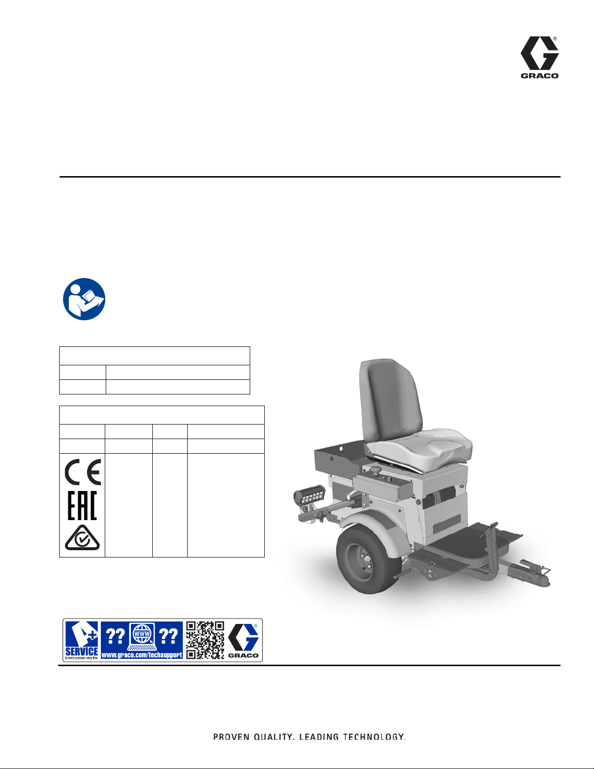
Operation, Repair, Parts
LineDriver™ ES
3A6623D
For the propulsion of line striping and removal equipment. Not approved for use in
explosive atmospheres or hazardous locations. For professional use only.
Models: 25N555, 25N556
10 mph (16 kph) Maximum Operating Speed
Important Safety Instructions
Read all warnings and instructions in this manual and in related LineLazer,
GrindLazer and ThermoLazer manuals before using the equipment. Save
these instructions.
Related Manuals:
710-0138 Delta-Q Battery Charger
3A6720 Hitch Receiver Kit
LineDriver ES
EN
Model Series Cord Adapter
--- 25N555 B North America
North America
Australia
CEE 7/7
25N556 B
Use only genuine Graco replacement parts.
The use of non-Graco replacement parts may void warranty.
Denmark
Italy
Switzerland
United Kingdom
Page 2

Contents
Warnings . . . . . . . . . . . . . . . . . . . . . . . . . . . . . . . . . 3
Component Identification . . . . . . . . . . . . . . . . . . . . 5
Setup . . . . . . . . . . . . . . . . . . . . . . . . . . . . . . . . . . . . . 6
12V Auxiliary Ports . . . . . . . . . . . . . . . . . . . . . . . 6
Startup . . . . . . . . . . . . . . . . . . . . . . . . . . . . . . . . . . . 7
Know Your Controls . . . . . . . . . . . . . . . . . . . . . . 7
Daily Inspections . . . . . . . . . . . . . . . . . . . . . . . . . 8
Operation . . . . . . . . . . . . . . . . . . . . . . . . . . . . . . . . . 9
Differences in Operation . . . . . . . . . . . . . . . . . . . 9
How to Operate . . . . . . . . . . . . . . . . . . . . . . . . . . 9
Operating on Inclines . . . . . . . . . . . . . . . . . . . . 10
Trailer Loading & Unloading . . . . . . . . . . . . . . . 10
Charging the Batteries . . . . . . . . . . . . . . . . . . . 11
Maintenance . . . . . . . . . . . . . . . . . . . . . . . . . . . . . . 13
Parking/Emergency Brake Adjustment or
Replacement . . . . . . . . . . . . . . . . . . . . . . . 13
Throttle Linkage Adjustment . . . . . . . . . . . . . . . 14
Coupler Adjustment . . . . . . . . . . . . . . . . . . . . . 15
Accelerator Calibration (Using Kit 25N880) . . . 15
Transaxle Service . . . . . . . . . . . . . . . . . . . . . . . 17
Repair . . . . . . . . . . . . . . . . . . . . . . . . . . . . . . . . . . . 18
Battery Pack Replacement . . . . . . . . . . . . . . . . 18
Battery Disposal . . . . . . . . . . . . . . . . . . . . . . . . 18
Transaxle Replacement . . . . . . . . . . . . . . . . . . . 19
Traction Motor Replacement . . . . . . . . . . . . . . . 19
Motor Controller Replacement . . . . . . . . . . . . . . 19
Troubleshooting - LineDriver . . . . . . . . . . . . . . . . 20
Troubleshooting - Motor Controller . . . . . . . . . . . 21
Parts Drawing . . . . . . . . . . . . . . . . . . . . . . . . . . . . . 26
Parts Drawing . . . . . . . . . . . . . . . . . . . . . . . . . . . . . 27
Parts Drawing - Detail Views . . . . . . . . . . . . . . . . . 28
Parts Drawing . . . . . . . . . . . . . . . . . . . . . . . . . . . . . 29
Parts List . . . . . . . . . . . . . . . . . . . . . . . . . . . . . . . . . 30
Wiring Diagram - Harness 25N661 . . . . . . . . . . . . 32
Wiring Diagram . . . . . . . . . . . . . . . . . . . . . . . . . . . 33
Wiring Diagram - Harness 25E406 . . . . . . . . . . . . 34
Technical Specifications . . . . . . . . . . . . . . . . . . . . 35
Graco Standard Warranty . . . . . . . . . . . . . . . . . . . 36
Graco Information . . . . . . . . . . . . . . . . . . . . . . . . . 36
2 3A6623D
Page 3
Warnings
Warnings
The following warnings are for the setup, use, grounding, maintenance, and repair of this equipment. The exclamation
point symbol alerts you to a general warning and the hazard symbols refer to procedure-specific risks. When these symbols appear in the body of this manual or on warning labels, refer back to these Warnings. Product-specific hazard sym-
bols and warnings not covered in this section may appear throughout the body of this manual where applicable.
MOVING VEHICLE HAZARD
Careless and reckless behavior causes accidents. Falling from vehicle, running into people or objects, or being
struck by other vehicles may result in serious injury or death.
•
Do not operate unless attached to line striping or line removal equipment.
•
Do not step on Direction/Speed Pedals.
•
Make turns slowly. Do not make turns greater than 45°.
•
Loss of traction may occur going downhill.
•
Do not operate on inclines greater than 7.5°.
•
Do not carry passengers.
•
Do not tow.
•
Use with line striping or line removal equipment only.
•
Use appropriate traffic control in all traffic areas. Refer to manual on Uniform Traffic Control Devices (MUTCD), U.S.
Department of Transportation, Federal Highway Administration or local highway and transportation regulations.
TRAFFIC HAZARD
Vehicle strikes may result in serious injury or death.
• Do not operate in traffic.
• Use traffic control.
ELECTRIC SHOCK HAZARD
This equipment must be grounded. Improper grounding, setup, or usage of the system can cause electric
shock.
• Turn off and disconnect power cord before servicing equipment.
• Connect only to grounded electrical outlets.
• Use only 3-wire extension cords.
• Ensure ground prongs are intact on power and extension cords.
• Do not expose to rain. Store indoors.
EQUIPMENT MISUSE HAZARD
Misuse can cause death or serious injury.
• Do not operate the unit when fatigued or under the influence of drugs or alcohol.
• Check equipment daily. Repair or replace worn or damaged parts immediately with genuine manufacturer’s
replacement parts only.
• Do not alter or modify equipment. Alterations or modifications may void agency approvals and create safety
hazards.
• Make sure all equipment is rated and approved for the environment in which you are using it.
• Use equipment only for its intended purpose. Call your distributor for information.
• Keep children and animals away from work area.
• Comply with all applicable safety regulations.
BURN HAZARD
Equipment surfaces and fluid that is heated can become very hot during operation. To avoid severe burns:
• Do not touch hot fluid or equipment.
3A6623D 3
Page 4
Warnings
120V US
230V
BATTERY HAZARD
Lead-acid batteries produce explosive gases and contain sulfuric acid that can cause severe burns. To avoid
sparks and injury when handling or working with a lead-acid battery:
• Only use the battery type specified for use with the equipment. See Technical Data.
• Read and follow the battery manufacturer’s warnings.
• Exercise caution when working with metallic tools or conductors to prevent short circuits and sparks.
• Keep all sparks, flames, and cigarettes away from batteries.
• Always wear protective eyewear and protective equipment for face, hands, and body.
• If you have direct contact with battery fluid, flush with water and consult a physician immediately.
• Installation and maintenance must be performed by knowledgeable personnel only.
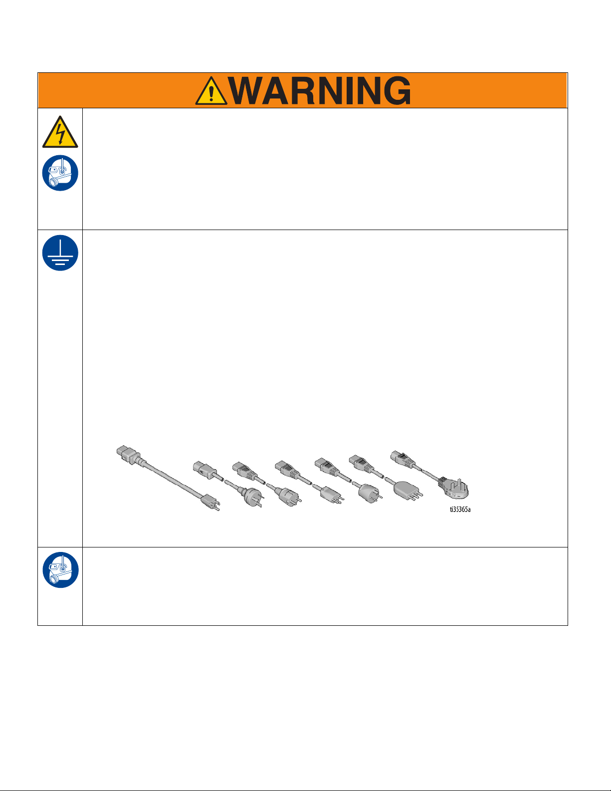
GROUNDING
This product must be grounded. In the event of an electrical short circuit, grounding reduces the risk of electric shock by providing an escape wire for the electric current. This product is equipped with a cord having a
grounding wire with an appropriate grounding plug. The plug must be plugged into an outlet that is properly
installed and grounded in accordance with all local codes and ordinances.
• Improper installation of the grounding plug is able to result in a risk of electric shock.
• When repair or replacement of the cord or plug is required, do not connect the grounding wire to either flat
blade terminal.
• The wire with insulation having an outer surface that is green with or without yellow stripes is the grounding
wire.
• Check with a qualified electrician or serviceman when the grounding instructions are not completely understood, or when in doubt as to whether the product is properly grounded.
• Do not modify the plug provided; if it does not fit the outlet, have the proper outlet installed by a qualified
electrician.
• This product is for use on a nominal 120V or 230V circuit and has a grounding plug similar to the plugs illustrated below.
• Only connect the product to an outlet having the same configuration as the plug.
• Do not use an adapter with this product.
PERSONAL PROTECTIVE EQUIPMENT
Wear appropriate protective equipment when in the work area to help prevent serious injury, including eye
injury, hearing loss, inhalation of toxic fumes, and burns. Protective equipment includes but is not limited to:
• Protective eyewear, and hearing protection.
• Respirators, protective clothing, and gloves as recommended by the fluid and solvent manufacturer.
4 3A6623D
Page 5
Component Identification
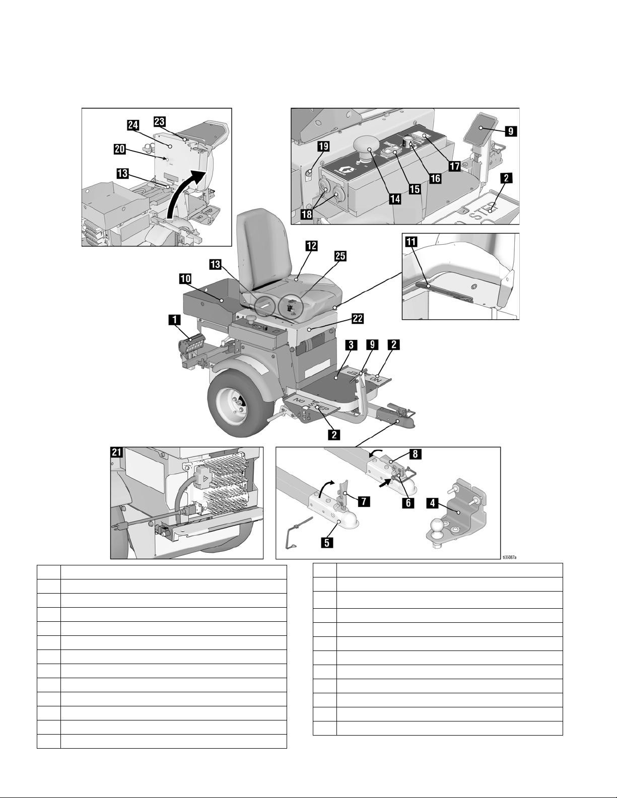
Component Identification
1 Headlight
2 Direction/Speed Pedals
3 Step Plate
4Hitch
5 Coupler
6 Safety Pin Location
7 Handle Open
8 Handle Locked
9 Parking/Emergency Brake
10 Tool Tray
11 Seat Adjustment
12 Operator Seat
13 Serial ID
3A6623D 5
14 Power Switch
15 Speed Switch
16
ExactMil
17 Voltage Meter
18 12V Aux. Power
19 Light Socket
20 Motor Controller Diagnostic Light
21 Battery Charger
22 Seat Lid
23 Buzzer
24 Seat Cover
25 Seat Interlock Switch
™
Speed Control
Page 6
Setup
ti11087a
ti10936a
M
ti11086a
ti11085a
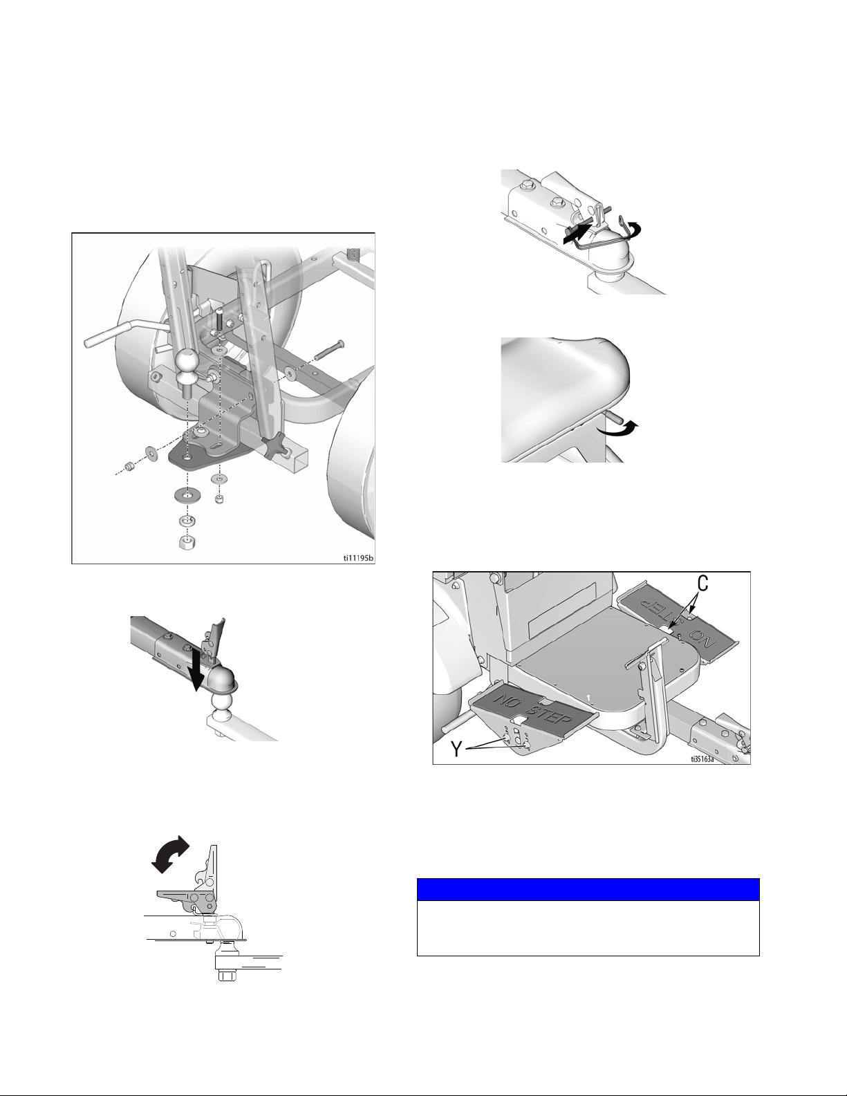
Setup
1. Install supplied ramp onto pallet.
2. Connect Hitch Receiver to line striping or line
removal equipment - Hitch Receiver Kit 25N787;
Manual 3A6720.
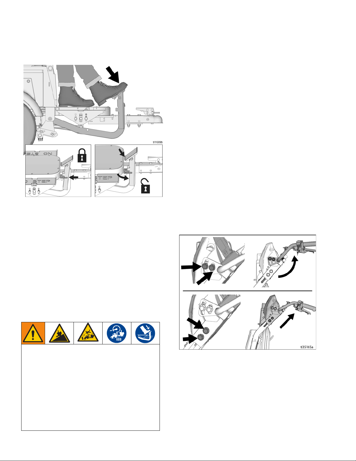
5. Insert safety pin in latch
6. Adjust seat forward/backward with lever below seat.
7. Adjust height of pedals to desired position by
removing/replacing bolts (Y).
8. Loosen two bolts (C) on topside of pedals. Rotate
pedal to desired position. Tighten bolts.
3. Install LineDriver Coupler to striper or grinder hitch
ball.
4. Latch Coupler to locked position (M).
NOTE: If Coupler is too tight to latch or is loose after
latching, Coupler needs adjustment. Refer to Coupler
Adjustment, page 15.
12V Auxiliary Ports
12V auxiliary power ports are provided to power accessories.
NOTICE
12V auxiliary ports must be used to power accessories.
Battery damage can result if other means are used to
power accessories.
6 3A6623D
Page 7
Startup
Startup
Know Your Controls
Direction/Speed Pedals
The Direction/Speed Pedals drive the LineDriver forward
and in reverse. Switching from forward to reverse creates
a braking action. When both feet are removed from the
pedals, the LineDriver stops. Use one or both feet to
operate the pedals.
Parking/Emergency Brake
The Parking/Emergency Brake stops the machine in an
emergency and prevents it from rolling when parked. To
engage the Parking/Emergency Brake, press brake
pedal firmly until it latches. To release, press the lower
edge of the brake pedal.
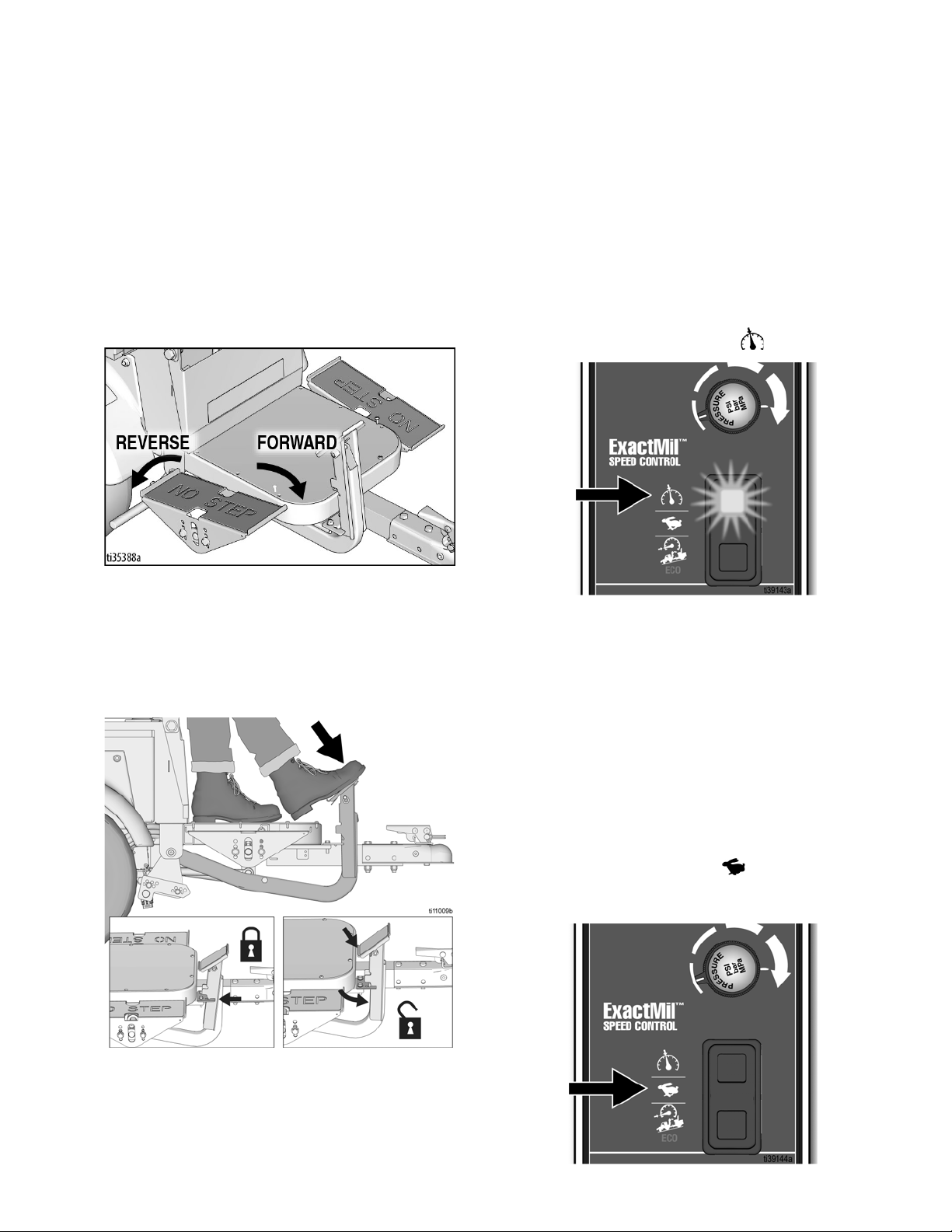
Speed Switch
ExactMil™ (Speed Control) Mode
ExactMil Mode ensures a consistent paint thickness by
holding the speed steady. To enable ExactMil mode:
1. Stop moving. Turn speed control knob all the way
counterclockwise.
2. Set Speed Switch to ExactMil position.
3. Depress foot pedal to go forward. Adjust speed control knob to desired speed setting.
NOTE: ExactMil speed control is only active when moving forward. Reverse speed is not impacted. ExactMil
speed control limits the maximum speed that can be
obtained with the pedal.
To disable ExactMil Mode:
• Return Speed Switch to center position.
Full Speed Mode
Set Speed Switch to the center position. This allows
a forward speed of 10 mph (16 kph) and a reverse speed
of 7 mph (11 kph).
3A6623D 7
Page 8
Startup
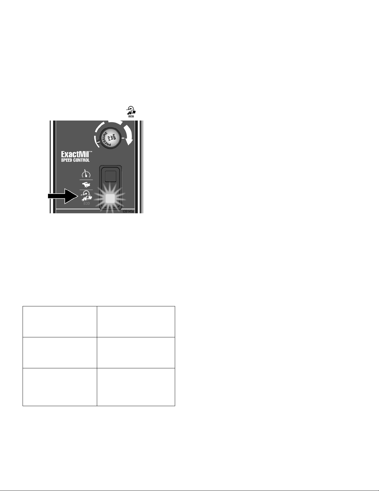
Incline/ECO Mode
Incline/ECO Mode is the recommended default mode for
all operations. It is helpful when greater control is
needed such as during loading or unloading and in congested areas. Incline/ECO mode should be used when
operating on inclines. It also extends battery life. To
enable Incline/ECO mode:
• Set Speed Switch to Incline/ECO position.
NOTE: Incline/ECO Mode limits forward speed to 5.5
mph (9 kph) and reverse speed to 4 mph (6 kph).
To disable Incline/ECO Mode:
• Return Speed Switch to center position.
Buzzer
A buzzer will sound to indicate different operating
conditions.
Single tone, about one
second long, after
turning the Power Switch
ON.
Repeating tone, about
every second.
Continuous tone while
traveling faster than 6.5
mph (10 kph).
Direction/Speed control
pedals now active.
Batteries are deeply
discharged. See
Charging the Batteries,
page 11.
Reduced braking available
from Direction/Speed
Pedals. See warning in
Extended Braking
Distance, page 10.
Daily Inspections
Perform the following inspections each day before using
the LineDriver ES.
1. Check battery charge level. Charge if not fully
charged.
2. Inspect Coupler for excess movement. Adjust if
needed. See Coupler Adjustment, page 15.
Replace Coupler when it is no longer adjustable.
3. Check function of the Seat Interlock Switch. The
Seat Interlock Switch stops the ES Driver when the
operator leaves the seat, and disables the Direction/Speed Pedals.
a. With the Parking/Emergency Brake ON, move
the Power Switch to the ON position while
standing next to the LineDriver ES.
b. Gently tap the Direction/Speed Pedals. The
LineDriver ES should not attempt to travel.
c. Sit on the seat and gently tap the Direc-
tion/Speed Pedals. The unit should attempt to
travel.
d. Service the Seat Interlock Switch if the Line-
Driver does not respond as described in steps b
and c above.
4. Test Parking/Emergency Brake function and adjustment.
a. Choose a flat open area. Accelerate unit to 3
mph (5 kph).
b. Cause the LineDriver ES to roll freely (free-
wheel) by moving the Power Switch to the OFF
position.
c. Stop unit by applying Parking/Emergency
Brake. To adjust brakes, see Parking/Emer-
gency Brake Adjustment or Replacement,
page 13.
8 3A6623D
Page 9
Operation
ti10937a
ti10935a
Operation
Differences in Operation
The LineDriver ES operates differently than a gasoline
powered LineDriver.
1. LineDriver ES rolls freely, especially on inclines,
when the power is off. Set Parking/Emergency
Brake before turning off.
2. Turn power on before releasing Parking/Emergency
Brake.
3. Performance drops when the battery charge
becomes low. When there is about one hour of runtime remaining, the Voltage Meter begins to flash.
When the batteries are deeply discharged and the
LineDriver ES is about to shut down, the buzzer
sounds about once per second.
4. The response of the Direction/Speed pedals is
softer. Learn this softer response before operating
on a job site.
How to Operate
1. Sit on seat to actuate Seat Interlock Switch. Ensure
Direction/Speed Pedals are not depressed.
2. Turn Power Switch ON. Buzzer will sound in a few
seconds, indicating that the Direction/Speed Pedals
are now active.
3. Disengage Parking/Emergency Brake on LineDriver
and any brakes on attached equipment.
5. Push striper or grinder handle bars to begin desired
turn.
FREEWHEEL HAZARD
Turning the Power Switch OFF will result in loss of
drive power. Loss of drive power causes LineDriver to
freewheel, which allows it to roll freely.
• Do not turn Power Switch OFF while LineDriver is in
motion.
• If loss of drive power occurs while LineDriver is in
motion, use the Parking/Emergency Brake to bring
LineDriver to a stop.
• Always engage Parking/Emergency Brake before
turning Power Switch OFF or standing up from
seat.
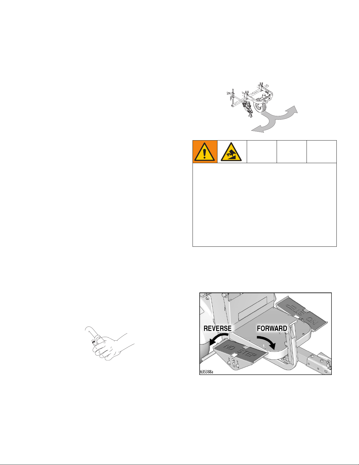
6. Move Direction/Speed pedals to drive the LineDriver, as shown below. Switching from forward to
reverse creates a braking action.
NOTE: LineDriver stops when both feet are removed
from pedals.
4. Squeeze hand control to release caster wheel of
attached equipment.
NOTE: LineDriver motion is forward and reverse. Turns
are made with the striper or grinder.
3A6623D 9
Page 10
Operation
7. Engage Parking/Emergency Brake when not operating LineDriver. This prevents rolling when on an
incline.
Operating on Inclines
Extended Braking Distance
Starting and Stopping on an Incline
1. Engage the Parking/Emergency Brake before turning the Power Switch to OFF when parking on an
incline.
2. Turn the Power Switch to ON, and allow the
machine to initialize before releasing the Parking/Emergency Brake when starting on an incline.
Trailer Loading & Unloading
NOTE: LineDriver ES rolls freely, especially on inclines,
when the power is off. Set Parking/Emergency Brake
before turning off. Turn power on before releasing Parking/Emergency Brake.
1. Always keep LineDriver connected to striper or
grinder.
2. Use a level surface to load and unload. Leave sufficient space behind ramps.
3. Use loading ramps of sufficient length and capable
of handling weight of unit and operator.
4. Adjust striper or grinder handlebar to highest position. Slide seat back as far as possible.
Operating on inclines results in extended braking distances.
1. Select Incline/ECO mode on Speed Switch when
operating on inclines.
2. Be prepared to use the Parking/Emergency Brake
when operating on inclines.
NOTE: Do not operate on inclines greater than 7.5
(13%).
REDUCED BRAKING HAZARD
The braking from the Direction/Speed pedals can be
significantly reduced when going down inclines at
speeds over 6.5 mph (10 kph). This reduced braking
results in longer braking distance than normal, which
could lead to an accident.
A continuous buzzer alarm will sound when this
reduced braking condition occurs. If this alarm
sounds, apply the Parking/Emergency Brake to slow
down. Failure to do so could result in serious injury.
• Do not drive in a manner that causes this alarm to
sound.
°
5. Use right foot to engage Parking/Emergency Brake.
Use left foot to control speed. Use ECO Mode to
limit speed.
6. Slowly drive straight up/down ramps (do not drive at
an angle).
7. Keep a firm grip on handlebars as the ramp is negotiated.
NOTE: Striper or grinder handlebars swing up/down as
the ramp is engaged/disengaged. Keep legs clear.
10 3A6623D
Page 11
Operation
Charging the Batteries
Replace and charge battery only in well-ventilated
area and away from flammable or combustible materials, including paints and solvents. The charger may
become hot while charging. Do not touch. Refer to
Charger Manual for additional information.
The charger may be used any time the LineDriver is not
being used. When the batteries are fully charged, the
charger automatically stops. If the LineDriver is stored
for an extended period, the batteries may self-discharge
enough for the charger to automatically recharge the
batteries. For optimum battery life, always leave the
charger plugged in.
NOTICE
Lead acid batteries can self-discharge in as little as 3
months depending on storage temperatures. The hotter
the storage temperature, the faster the self-discharge
occurs. To prevent damage to the battery, it is important to keep the battery in a charged state.
Batteries are fully charged when leaving the factory.
Due to self-discharging of the battery, charge battery
before first use. It takes ~18 hours to charge a fully
depleted battery, and ~8 hours to charge the battery 3/4
full.
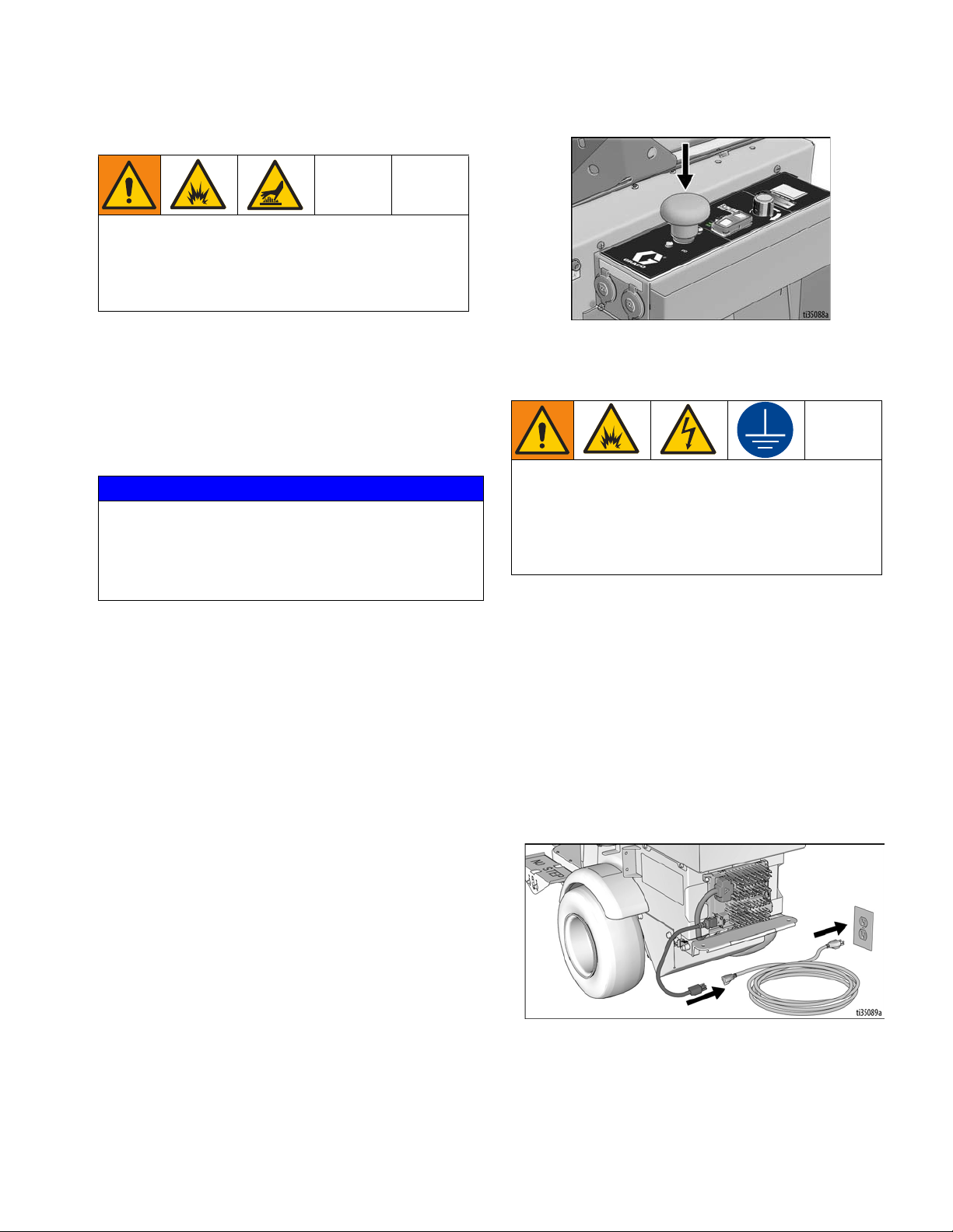
3. Ensure Power Switch is in OFF position.
4. Plug charging cord into charging port on the unit.
Connect an extension cord, per charger manual, to
the charging cord and plug it into wall power.
This equipment must be grounded to reduce the risk
of static sparking and electric shock. An electric
shock or static spark can cause fumes to ignite or
explode. An improper ground can cause electric
shock. A good ground provides an escape wire for
the electric current.
Always use an outlet that is properly installed and
grounded in accordance with all local codes and ordinances.
Do not modify the plug provided; if it does not fit the
outlet, have the proper outlet installed by a qualified
electrician.
NOTE: Battery life depends on the depth of discharge
per cycle. A battery that is discharged to 50% depth will
get over twice as many cycles in its life compared to it
being discharged to 100% depth each cycle.
1. Place unit in dry, well-ventilated area and away from
flammable or combustible materials, including
paints and solvents.
2. Position the driver so the wheels are on a true
grounded surface, not on pavement.
3A6623D 11
Power Requirements
• All models use the same battery charger. Refer to
Technical Specifications, page 35, for power
requirements.
Page 12

Operation
DISPLAY
CHARGING
OUTPUT
INICATOR
USB PORT
STATE OF
CHARGE
INDICATOR
FAULT
INDICATOR
5. The Charging Output Indicator means that the charger output is active.
6. When power is connected, charger will immediately
begin charging.
NOTE: Battery will charge to ~30 volts while charging
and then it will come back down to ~27 volts after fully
charging.
ti35137a
NOTE: The Charge Display may show codes to indicate
different conditions. Refer to charger manual for addi-
tional information.
• ‘F’ codes meaning that an internal fault condition
has caused charging to stop.
• ‘E’ codes meaning that an external error condition
has caused charging to stop.
7. When battery charge indicator is solid green, the
charge is complete.
12 3A6623D
Page 13

Maintenance
Maintenance
Parking/Emergency Brake
Adjustment or Replacement
1. Block tires so LineDriver will not move. Release
Parking/Emergency Brake.
2. Ensure Power Switch is in OFF position.
3. Inflate tires to operating pressure per tire sidewall.
Remove two bolts securing brake rod.
4. Select a hole pattern that positions the brake rod 1/8
to 1/4 in. from the tire.
5. Install two bolts and secure brake rod. Repeat for
second tire.
NOTE: Brake rods are not interchangeable from side to
side. Model shown in the graphic above is the right side
version.
3A6623D 13
Page 14

Maintenance
Throttle Linkage Adjustment
14 3A6623D
Page 15

Coupler Adjustment
Maintenance
A Coupler too tight or too loose needs to be adjusted.
Before adjusting, check ball and Coupler for wear.
Replace entire Coupler if unable to tighten it.
Ensure Power Switch is in OFF position.
3A6623D 15
Page 16

Maintenance
Accelerator Calibration (Using Kit 25N880)
1. Turn power OFF. Engage Parking/Emergency
Brake.
2. Slowly raise hitch Coupler until LineDriver rests on
rear bumper.
3. Remove accelerator from LineDriver.
4. Connect calibration cable per illustration. Use a Digital Multi-Meter to measure volts DC.
5. Mount accelerator to calibration plate and plate to
pedal. This makes it easier to torque fasteners.
6. Ensure nothing is on the operator’s seat so the Seat
Interlock Switch prevents wheel movement. Turn
power ON.
7. Loosen adjustment fastener and set neutral position
voltage to 2.45 ± .05 volts. Use calibration plate to
hold accelerator in this position. Torque adjustment
fastener to 90-100 in-lbs.
8. Rotate accelerator arm back and forth, then return it
to neutral position. Re-adjust voltage if necessary.
Turn power OFF.
9. Install accelerator onto LineDriver. When connecting linkage, adjust tie rod end so no pressure is
needed to align parts. Otherwise the LineDriver will
creep.
10. LineDriver may creep forward or reverse when
turned on. As a precaution, jack unit up and use jack
stands to support it (two under the frame in the rear
and one under the Coupler).
11. Connect the LineDriver to a striper or grinder, sit on
the seat and turn on. If wheels do not turn (with no
pressure on speed pedals), calibration is complete.
If they do turn, follow Throttle Linkage Adjust-
ment, page 14.
16 3A6623D
Page 17

Transaxle Service
Maintenance
Check Oil Level (Annually)
1. Turn power OFF. Engage Parking/Emergency
Brake.
2. Slowly raise hitch Coupler until LineDriver rests on
rear bumper.
3. Remove fill plug from transaxle cover.
5. Reinstall plug.
Change Oil (recommended every 3 years)
1. Turn power OFF. Engage Parking/Emergency
Brake.
2. Slowly raise hitch Coupler until LineDriver rests on
rear bumper.
3. Place pan under transaxle cover. Remove screws
and cover.
NOTE: Sealant may hold cover on. If necessary, pry
cover off.
4. Allow oil to drain completely. Follow local ordinances and regulations for disposal.
5. Clean cover and housing where sealant is used.
Apply new sealant (recommended is RTV silicone).
6. Reinstall cover with screws.
7. Remove drain plug. Fill with 22 oz. of Mobilfluid™
424.
4. Slowly lower hitch Coupler. Oil will begin to flow out
of transaxle when hitch Coupler is lowered to 10.5 -
12.5” from the floor. Add or remove oil as needed.
8. Check oil level per above. Reinstall plug.
9. Check for oil leaks. Fix if necessary.
3A6623D 17
Page 18

Repair
Repair
Battery Pack Replacement
NOTE: Prior to replacing batteries, use Troubleshooting - LineDriver, page 20, to determine if the batteries
are the cause of the problem. Also, use a battery load
tester to confirm the batteries need replacement. Always
replace all four batteries.
1. Turn Power Switch OFF. Turn lights OFF. Disconnect 12V accessories.
2. Remove Tool Tray.
3. Remove rear screws of Seat Lid.
4. Pivot Operator Seat forward slowly.
6. Remove battery holders. Remove batteries and
recycle according to below.
7. Install new batteries in orientation shown. Install
holders and cables.
8. Reinstall seat and Tool Tray.
5. Remove battery cables.
9. Charge batteries. See
11.
Charging the Batteries
, page
Battery Disposal
Do not place batteries in the trash. Recycle batteries
according to local regulations.
18 3A6623D
Page 19

Repair
Transaxle Replacement
1. Turn power OFF.
2. Remove rear screws of Seat Lid. Pivot seat forward
slowly.
3. Disconnect battery cables to motor controller.
4. Jack unit up and use jack stands to support unit (two
jacks at the rear and one jack in the front). Raise
wheels about 2 inches off the floor, leaving enough
room to pull the transaxle out.
5. Remove wheels.
6. Remove motor cover.
7. Disconnect wires attached to motor.
8. Place a support under motor and remove transaxle.
9. Place new transaxle under unit. Lay motor wires on
transaxle.
10. Bolt new transaxle to frame.
11. Connect wires to motor. Take care when attaching
the three large cables to prevent damage to the
plastic terminal block on the motor.
Motor Controller Replacement
1. Turn power OFF.
2. Remove rear screws of Seat Lid. Pivot seat forward
slowly.
3. Disconnect battery cables to motor controller. Tape
over terminals to prevent accidental contact.
4. Remove Seat Cover to expose motor controller.
5. Disconnect wires from motor controller.
6. Remove nuts holding motor controller in place.
7. Install new motor controller.
8. Connect wires to new motor controller. Be sure 35
pin connector latches.
9. Install Seat Cover.
10. Reconnect battery cables. Pivot seat back and reinstall rear screws of Seat Lid.
11. LineDriver may creep forward or reverse when
turned on. As a precaution, jack unit up and use jack
stands to support it (two under the frame in the rear
and one under the Coupler).
12. Install motor cover.
13. Install wheels.
14. Lower unit to the floor and reconnect the battery
cables.
15. Reinstall Operator Seat.
Traction Motor Replacement
Follow Transaxle Replacement, page 19.
12. Sit on the seat and turn on. If wheels turn with no
pressure on speed pedals, follow the Accelerator
Calibration Procedure, page 16.
3A6623D 19
Page 20

Troubleshooting - LineDriver
Troubleshooting - LineDriver
PROBLEM CAUSE SOLUTION
Parking/Emergency Brake
Driver from moving
LineDriver creeps in forward or reverse direction Throttle linkage too long or too short Adjust throttle linkage
Head light does not turn on Connections Repair connections
LineDriver does not move forward or reverse Voltage Meter ON
LineDriver does not move forward or reverse Voltage Meter OFF
LineDriver only moves slowly
Battery charger not charging Batteries already charged Charge batteries after voltage drops below
Batteries discharge within 6 hours of usage
(even when charged overnight)
Hitch Coupler too tight to latch or too loose after
latching
Voltmeter flashes ON/OFF Batteries discharged and less than one hour of
Buzzer sounds about once per second Batteries deeply discharged and system about
does not keep Line-
Buzzer sounds continuously when traveling
over 6.5 mph (10 kph).
Parking Brake needs adjustment Adjust Parking Brake
Tire pressure too low Adjust pressure per tire sidewall
LED Replace light
Open 10 amp fuse Address cause of high current Replace fuse
Switch Replace switch
Batteries discharged Charge batteries at least 2 hours
Seat Interlock Switch Sit on seat
Speed pedals engaged while turning unit on Disengage pedals then turn unit on
Speed pedals engaged for 15 seconds with no
LineDriver movement
Motor Controller fault Follow Troubleshooting - Motor Controller
Batteries discharged Charge batteries at least 2 hours
Power Switch OFF Pull knob up
Open 20 amp fuse Address cause of high current Replace fuse
Open 300 amp fuse Address cause of high current Replace fuse
Turn Power Switch OFF then back ON to reset
motor controller
instructions, page 21
Parking/Emergency Brake engaged Disengage Parking/Emergency Brake
Batteries discharged Charge batteries at least 2 hours
™
ExactMil
ECO Mode ON Turn OFF
Motor Controller fault Follow Troubleshooting - Motor Controller
Charger has error or fault code Clear code. See charger manual
Speed Control ON
Parking/Emergency Brake engaged
Wheels rubbing Clear material away from wheels
Batteries unable to hold charge Replace all four batteries
Charger has error or fault code Clear code. See charger manual
LineDriver hitch Coupler too loose or tight on
ball
runtime left
to shut off
Braking from Direction/Speed Control pedals
is significantly reduced.
Increase speed setting or turn OFF
instructions, page 21
25.0V
Disengage brake while operating
Adjust Coupler
Charge batteries at least 2 hours
Charge batteries at least 2 hours
Slow down. Apply Parking/Emergency Brake
as needed.
20 3A6623D
Page 21

Troubleshooting - Motor Controller
Troubleshooting - Motor Controller
Diagnostics
Diagnostics information can be obtained by observing
the fault codes issued by the Status LEDs. See Table 1
for a summary of LED display formats.
The pair of LEDs built into the controller (one red, one
yellow) produce flash codes displaying all the currently
set faults in a repeating cycle. Each code consists of two
digits. The red LED flashes once to indicate that the first
digit of the code will follow: the yellow LED then flashes
the appropriate number of times for the first digit. The
red LED flashed twice to indicate that the second digit of
the code will follow; the yellow LED flashes the appropriate number of times for the second digit.
Example:
B+ Under voltage Cutback (code 23) and Stall Detected
(code 73).
The controller’s two LEDs will display this repeating pattern:
Code Display
23 One red, two yellow, two red, three yellow
73 One red, seven yellow, two red, three yellow
Summary of LED Display Formats
The two LEDs have four different display modes, indicating the type of information they are providing.
Table 1
Display Status
Neither LED illuminated
Yellow LED flashing
Yellow and red
LEDs both on solid
Red LED on solid Internal hardware fault detected by the
Red LED and yellow LED flashing
alternately
Controller is not powered on, or
Vehicle has dead battery, or
Severe damage
Controller is operating normally
Controller is in Flash program mode
Supervisor or Primary microprocessor.
Missing or corrupt software. Interrupting
a software download may cause corruption of the software. Cycle Power Switch
to clear. Reload software or replace controller if necessary.
Controller has detected a fault. 2-digit
code flashed by yellow LED identifies
the specific fault; one or two flashes by
red LED indicate whether first or second
code digit will follow.
The numerical codes used by the yellow LED are listed
in Table 2, page 22, which also lists possible fault
causes and describes the conditions that set and clear
each fault.
NOTE: If there are more than one errors active at one
time, the control will cycle through them and repeat.
3A6623D 21
Page 22

Troubleshooting - Motor Controller
NOTE: When a fault is encountered, shut off the Power Switch and turn it back on to see if the fault clears. If it
does not, shut off the Power Switch and remove the 35-pin connector. Check the connector for corrosion or
damage, clean if necessary, and re-insert connector. If the fault persists, follow the instructions below. When
inspecting a cable, always check for a loose terminal fastener, a loose crimp, corrosion, and connector or insulation damage. Repair or replace components as needed.
Table 2
CODE DESCRIPTION POSSIBLE CAUSE SET / CLEAR CONDITIONS SOLUTION
1. Inspect motor cables U,V,W.
Visually inspect motor terminal block for external short circuit.
2. Measure resistance between
U, V, W cables and frame of
motor. If resistance is less
than 1 megohm, replace
motor or controller.
1. Inspect motor cables U,V,W.
Visually inspect motor terminal block for external short circuit.
2. Measure resistance between
U, V, W cables and frame of
motor. If resistance is less
than 1 megohm, replace
motor or controller.
1. Inspect all cables and connectors from batteries to controller.
2. Remove any after market
devices that could draw power
during system power up. Only
use designated auxiliary ports
for after market devices.
1. Move the unit to a warmer
area.
1. Move the unit to a cooler area.
2. Reduce operating load on
vehicle.
3. Inspect controller heatsink
mounting for air gaps and
tighten fasteners.
Controller Overcur-
12
rent
Current Sensor
13
Fault
14 Pre-charge Failed
Controller Severe
15
Undertemp
Controller Severe
16
Overtemp
1. External short of phase
U, V, or W motor connections.
2. Controller defective.
1. Leakage to vehicle
frame from phase U, V,
or W (short in motor
stator).
2. Controller defective.
1. External load on battery pack (B+ connection terminal) that
prevents the controller
from charging.
1. Controller is operating
in an extreme environment.
1. Controller is operating
in an extreme environment.
2. Excessive load on
vehicle.
3. Improper mounting of
controller.
Set: Phase current exceeded the
current measurement limit.
Clear: Cycle Power Switch.
Set: Controller current sensors
have invalid offset reading.
Clear: Cycle Power Switch.
Set: The pre-charge failed to
charge the capacitor bank.
Clear: Cycle Power Switch.
Set: Heatsink temperature below
-40°C.
Clear: Bring heatsink temperature above -40°C, and cycle
Power Switch.
Set: Heatsink temperature above
+95°C.
Clear: Bring heatsink temperature below +95°C, and cycle
Power Switch.
22 3A6623D
Page 23

Troubleshooting - Motor Controller
CODE DESCRIPTION POSSIBLE CAUSE SET / CLEAR CONDITIONS SOLUTION
Severe B+ Undervoltage
17
1. Non-controller system
drain on battery.
2. Battery resistance too
high.
3. Battery disconnected
while driving.
4. Open B+ fuse or main
contractor did not close
Set: Battery pack voltage
dropped below the Severe
Undervoltage limit with FET
bridge enabled.
Clear: Bring battery pack voltage
above Severe Undervoltage limit.
1. Inspect all cables and connectors from batteries to controller.
2. Let battery cool then fully
recharge battery. If error happens again, load test battery
and replace if needed.
3. Inspect 300 amp fuse and
replace if open.
4. Inspect contactor for corroded contacts and replace if
needed.
1. Non-controller system
Set: Below Brownout Voltage for
2 seconds.
Clear: Bring Power Switch voltage above Brownout Voltage.
1. Inspect all Power Switch
cables and connectors.
2. Inspect 20 amp fuse and
replace if open.
Severe Power
Switch Undervoltage
drain on battery/Power
Switch circuit wiring.
2. Power Switch disconnected while driving.
3. Open 20 amp fuse.
Severe B+ Overvoltage
18
Severe Power
Switch Overvoltage
1. Battery resistance too
high for given regen
current.
2. Battery disconnected
while regen braking.
1. Incorrect (too high) battery-voltage applied to
Power Switch (pin 1).
NOTE: Prevents Main Contactor closure if Power
Switch is greater than the
Severe Overvoltage limit.
Set: Battery pack voltage
exceeded the Severe Overvoltage limit with FET bridge
enabled.
Clear: Bring battery pack voltage
below Severe Overvoltage limit,
and then cycle Power Switch.
Set: Power Switch voltage
exceeded Severe Overvoltage
limit.
Clear: Bring Power Switch voltage below the Severe Overvoltage limit.
1. Let battery cool then fully
recharge battery. If error happens again, load test batteries
and replace if needed.
2. Inspect all cables and connectors from batteries to controller.
1. Check the voltage of each 6V
battery with a digital volt
meter. Inspect Power Switch
and battery wiring for insulation damage and proper wiring.
1. Controller is performance-limited at this
1. Move the unit to a cooler area.
2. Reduce operating load on
vehicle.
3. Inspect controller heatsink
mounting for air gaps and
tighten fasteners.
Controller Over-
22
temp Cutback
temperature.
2. Controller is operating
in an extreme environment.
3. Excessive load on
vehicle.
Set: Heatsink temperature
exceeded 85°C.
Clear: Bring heatsink temperature below 85°C.
4. Improper mounting of
controller.
3A6623D 23
Page 24

Troubleshooting - Motor Controller
CODE DESCRIPTION POSSIBLE CAUSE SET / CLEAR CONDITIONS SOLUTION
B+ Undervoltage
23
Cutback
1. Normal operation.
Fault indicates the batteries need recharging. Controller is
performance limited at
this voltage.
2. Battery resistance too
high.
3. Battery disconnected
while driving.
4. Open 300 amp fuse or
main contactor did not
close.
5. Non-controller system
drain on battery.
Set: Battery pack voltage
dropped below the Undervoltage
limit with the FET bridge enabled.
Clear: Bring battery pack voltage
above the Undervoltage limit
(19V).
1. Charge batteries.
2. Let battery cool then fully
recharge battery. If error happens again, load test batteries
and replace if needed.
3. Inspect all cables and connectors from batteries to controller.
4. Inspect 300 amp fuse and
replace if needed.
5. Inspect contactor for damaged, corroded or contaminated contacts. Repair or
replace as needed.
1. Normal operation.
Fault shows that regen
B+ Overvoltage Cut-
24
back
braking currents elevated the battery voltage during regen
braking. Controller is
performance limited at
this voltage.
Set: Battery pack voltage
exceeded the Overvoltage limit.
Clear: Bring battery pack voltage
below the Overvoltage limit
(30V).
1. Continue using the unit.
2. Inspect all cables and connectors from batteries to controller.
2. Battery disconnected
while regen braking.
1. Inspect motor encoder/thermistor cable and connector. Disconnect motor encoder and
cycle unit power. If the 5V
supply fault clears, replace the
motor. If the 5V supply fault
persists, reconnect encoder
and repeat this process for the
throttle assembly and Exact-
25 +5V Supply Failure
1. Bad crimps or faulty
wiring.
2. Shorted motor
encoder.
3. Shorted throttle.
4. Shorted ExactMil
potentiometer.
Set: +5V supply (pin 26) outside
the 5 V±10% range.
Clear: Bring voltage within range.
Mil potentiometer.
Motor Temp Hot
28
Cutback
1. Motor temperature is at
or above the programmed Temperature Hot setting, and
the current is being cut
back.
Set: Motor temperature is at or
above the Temperature Hot
parameter setting.
Clear: Bring the motor temperature within range.
1. Move to cooler area, reduce
operating load.
Set: Motor thermistor input (pin
Motor Temp Sensor
29
Fault
1. Motor thermistor is not
connected properly.
8) is at the voltage rail (0V or 10
V).
Clear: Bring the motor thermistor
1. Inspect motor encoder/thermistor cable and connector.
input voltage within range.
Set: Main contactor driver (pin 6)
is either open or shorted. This
fault can be set only when Main
Enable = ON.
Clear: Correct open or short, and
cycle Power Switch.
Set: Motor encoder phase failure
detected.
Clear: Cycle Power Switch.
1. Inspect contactor coil cables
and connectors.
2. Test the contactor coil and
replace contactor if needed.
1. Inspect motor encoder/thermistor cable and connector.
2. Replace motor.
Main Contactor
31
Open/Short
36 Encoder Fault
1. Open or short across
contractor coil.
2. Dirty connector pins.
3. Bad crimps or faulty
wiring.
1. Motor encoder failure.
2. Bad crimps or faulty
wiring.
24 3A6623D
Page 25

Troubleshooting - Motor Controller
CODE DESCRIPTION POSSIBLE CAUSE SET / CLEAR CONDITIONS SOLUTION
Set: Motor phase U, V, or W
detected open.
Clear: Cycle Power Switch.
1. Inspect U, V, W cables.
2. Replace motor.
37 Motor Open
1. Motor phase is open.
2. Bad crimps or faulty
wiring.
1. Main contactor tips are
Main Contactor
38
Welded
welded closed.
2. Motor phase U or V is
disconnected or open.
3. An alternate voltage
path is bypassing the
contractor between
battery and B+ on the
controller before the
Set: Just prior to the main contactor closing, the battery pack
voltage (B+ connection terminal)
was loaded for a short time and
the voltage did not discharge.
Clear: Cycle Power Switch.
1. Inspect contactor for welded
contacts and replace if necessary.
2. Inspect all cables from the
battery pack to controller looking for insulation damage.
3. Inspect U, V, W cables.
contractor engages.
1. Main contactor did not
Main Contactor Did
39
Not Close
close.
2. Main contactor tips are
oxidized, burned, or
not making good contact.
3. External load on battery pack (B+ connection terminal) that
prevents battery pack
from charging.
4. Blown 300 amp fuse.
Set: With the main contactor
commanded closed, the battery
pack voltage (B+ connection terminal) did not charge to B+.
Clear: Cycle Power Switch.
1. Inspect contactor cable and
connectors.
2. Inspect all cables and connectors from batteries to controller.
3. Inspect contactor contacts for
damage or corrosion and
repair or replace contactor.
4. Inspect 300 amp fuse and
replace if needed.
41 Throttle Open
42 Throttle Short
HPD/Sequencing
47
Fault
73 Stall Detected
Encoder Pulse
88
Count Fault
1. Throttle wiper voltage
too high.
1. Throttle wiper voltage
too low.
1. Power Switch, seat,
and throttle inputs
applied in incorrect
sequence.
2. Faulty wiring, crimps,
or switches at Power
Switch, seat, or throttle
inputs.
1. Stalled motor.
2. Motor encoder failure.
3. Bad crimps or faulty
wiring.
4. Problems with power
supply for the motor
encoder.
1. Encoder Steps parameter does not match
the actual motor
encoder.
Set: Throttle wiper (pin 16) voltage is higher than the high fault
threshold.
Clear: Bring throttle wiper voltage
below the fault threshold.
Set: Throttle wiper (pin 16) voltage is lower than the low fault
threshold.
Clear: Bring throttle wiper voltage
above the fault threshold.
Set: HPD (High Pedal Disable) or
sequencing fault caused by
incorrect sequence of Power
Switch, seat, and throttle inputs.
Clear: Reapply inputs in correct
sequence (neutral throttle,
power, seat switch).
Set: No motor encoder movement detected.
Clear: Cycle Power Switch.
Set: Detected wrong setting of
the Encoder Steps parameter.
Clear: Cycle Power Switch.
1. Inspect throttle cable insulation and connectors for damage and repair or replace
where needed.
2. Replace throttle assembly.
1. Inspect throttle cable and connectors.
2. Replace throttle assembly.
1. Cycle power with no pressure
on Speed Pedals.
2. If error persists, inspect throttle and seat switch cables.
3. Recalibrate the accelerator
assembly. Refer to Accelera-
tor Calibration, page 16.
4. Replace throttle assembly.
1. Reduce load on driver so it
can move with applied throttle.
2. Inspect encoder/thermistor
cable. Verify motor wires U, V,
W are properly wired.
3. Replace motor.
4. Replace controller.
1. Inspect motor encoder/thermistor cable.
2. Replace motor.
3A6623D 25
Page 26

Parts Drawing
Torque cable cap screws or nuts
to 7-8 ft-lbs (9-11 N·m)
1
1
1
1
1
Parts Drawing
26 3A6623D
Page 27

Parts Drawing
Torque to 8-9 ft-lbs (11-12 N·m)
Torque to 40-60 ft-lbs (54-81 N·m) in
criss-cross sequence
Torque to 16-20 ft-lbs (22-27 N·m)
Torque to 10-11 ft-lbs (14-15 N·m)
Torque to 1.8-2.3 ft-lbs (2.5-3.2 N·m)
1
2
3
4
5
2
1
3
4
4
5
Parts Drawing
3A6623D 27
Page 28

Parts Drawing - Detail Views
Torque to 6-7 ft-lbs. (8-9 N·m)
Torque to 20-25 ft-lbs (27-34 N·m)
Torque to 90-115 ft-lbs (122-156 N·m)
Torque to 95-105 in-lbs (10.7-11.9 N·m)
Use a wrench to support backup nuts firmly
while tightening.
1
2
3
4
1
2
3
4
181
Parts Drawing - Detail Views
28 3A6623D
Page 29

Parts Drawing
Clamped parts must move
freely after tightening
1
1
1
1
Parts Drawing
3A6623D 29
Page 30

Parts List
Parts List
Ref. Part Description Qty
1 25N649 FRAME, electric LineDriver
2 15N470 PLATE, floor
3 25N776 KIT, throttle, includes 180
4 15R872 INSERT, bearing, flange
5 116887 BEARING, flanged, bronze
6 15R794 SHAFT, foot pedal
7 247901 PLATE, linkage
8 25N760 PEDAL, foot, adjustment
9 121234 PAD, non-slip, pedal
10 109570 WASHER, plain
11 116889 COUPLER, ball
12 113696 PIN, ball coupler
13 247571 BRACKET, brake
14 15R123 SPRING
15 15R068 LATCH, brake
16 247572 PEDAL, foot brake
17 15R409 PAD, non-slip, brake
18 15R122 SPRING
19 19B111 BRAKE, adjustment, right
20 19B112 BRAKE, adjustment, left
21 290159 LABEL, reflective
22 17C773 BALL, joint, rod end
23 17Z351 ROD, straight linkage
24 25N527 DAMPENER, pedal
25 103746 NUT, jam, hex, 3/8-24
26 104541 NUT, lock, M8
27 15R472 FASTENER, hex hd, flanged
28 110037 SCREW, mach, pnh
29 125585 SCREW, cap, hex hd
30 102040 NUT, lock, hex
31 100527 WASHER, plain
32 121280 SCREW, cap, hex hd
33 115348 SCREW, cap, 3/8-16 hex hd,
5/16-18
34 101566 NUT, lock, 3/8-16
35 100023 WASHER, flat
36 121256 SCREW, shoulder, skt hd
37 802127 SCREW, cap, hex hd
38 110838 NUT, lock
39 249083 WHEEL pneumatic, assy
40 125481 NUT, wheel
41 25N488 AXLE, transaxle, includes 155,
156, 157, 172, 173, 174, 175
42 25N521 MOTOR, transaxle, includes 158
43 17Y182 GUARD, motor
44 116780 SCREW, hexed, hd, flanged
45 16X378 SCREW, hex flange, M6
22
18
Ref. Part Description Qty
47 100521 SCREW, cap, hex head
1
48 111040 NUT, lock, insert, nylock, 5/16
1
49 25N471 CARRIAGE
2
2
50 25N476 LID, seat, paint
2
51 100424 SCREW, cap, hex hd
1
52 801020 NUT, lock, hex
1
53 113796 SCREW, flanged, hex hd
2
54 25N477 BASE, controls, paint
2
56 17X959 FENDER
2
57 112798 SCREW, thread forming, hex hd
1
58 247544 HOLDER, bottle
1
59 245341 SEAT, includes 69, 82 (x4)
1
61 25N483 CONVERTER, power
1
62 19C163 MOTOR, controller
1
63 25N487 BATTERY, contactor
1
64 17N816 HOLDER, fuse
1
65 131738 FUSE, 300 amp
1
66 25N482 SWITCH, push button, shut off
1
67 25N625 SWITCH, rocker
1
68 17N638 METER, volt, digital
1
69 116833 SWITCH, safety, seat
2
70 25E406 CABLE, harness, 12 vdc supply
1
71 25N649 PLUG, panel
1
72 25N475 COVER, seat, paint
2
73 17X949 TRAY, tool
2
74 17Y217 SOCKET, 12V
2
75 16P138 LABEL, energy source
76 198918 LABEL, warning
4
77 25N529 LABEL
78 25N526 POST, distribution
4
79 16V700 GROMMET
6
80 25N480 BATTERY, charger
2
81 15T120 LABEL, instruction
82 110996 NUT, hex, flange hd
2
83 125943 NUT, serrated flange, 7/16-14
2
84 17M849 BOLT, flange, serrated
2
85 103229 SCREW, cap sch
2
86 187797 SPACER, duct
2
87 17X783 ISOLATOR, hvlp
2
88 17P951 POTENTIOMETER, assy
8
89 17N957 KNOB, potentiometer
1
90 25N884 BATTERY, deep cycle, 6v,
includes 90a, 90b, 90c,112
1
90a M8x1.25x16mm capscrew
1
90b M8 lockwasher
8
90c M8 flatwasher
6
91 116895 CAP, tube, square
2
4
1
1
2
2
2
1
1
4
1
1
1
1
1
1
1
1
1
1
1
1
1
1
1
2
2
2
2
1
1
1
1
19
4
4
2
1
1
1
1
4
8
8
16
2
30 3A6623D
Page 31

Parts List
Ref. Part Description Qty
92 17X783 WASHER, nylon
93 15R063 BRACKET, light
94 15R064 SUPPORT, light
95 17R099 TUBE, bracket, light, LED
96 17R098 LIGHT, LED
97 111145 KNOB, pronged
98 114425 BUSHING, strain relief
99 15R308 CORD, power
100 15R864 KNOB
101 111800 SCREW, cap, hex hd
102 111930 SWITCH, toggle
103 107255 GUARD, switch
104 195428 BOOT, toggle
105 105658 RING, locking
106 17N758 CORD, power, 125V, US
107 278204 CLIP, drain line
108 129627 SPACER, nylon, 3/8 ID
109 15C753 SCREW, mach, hex wash hd
111 17Y311 LABEL, controls
112 17Y312 LABEL, battery, 6v
113 17Y313 LABEL, max wattage
115 17Y315 BRACKET, contactor
116 117018 WASHER
117 108050 WASHER, lock, spring
118 112117 SCREW, cap, hex hd, M6
119 15T112 LABEL
120 195793 LABEL, warning
121 17K396 LABEL, safety
122 17Y094 LABEL, safety, prop 65
123 129696 SCREW, pan hd
124 25N604 INDICATOR, buzzer
126 25E392 CABLE, red, dia. .525 x 15 in.
127 25E393 CABLE, black, dia. .525 x 13 in.
128 25E391 CABLE, red, dia. .525 x 10 in.
129 25E388 CABLE, black, dia. polarized
130 25E389 CABLE, black, dia. .525 x 20 in.
131 25E390 CABLE, red, dia. .525 x 20 in.
132 404989 STRAP, tie
133 25N661 HARNESS, controls
134 25N660 HARNESS, assembly
135 25N652 CLAMP, loop
136 25N647 HOLDER, battery
137 17Y588 SCREW, cap
138 15R608 SPACER, duct, .50 x .75 x .062
141 SERIAL ID
142 109032 SCREW, mach, pnh
143 25N750 PAD, adhesive mounting
146 25N758 BRACKET
147 25N757 FILTER, LED
148 25N759 COLLAR
Ref. Part Description Qty
1
149 110963 SCREW, cap, flange hd
1
153 126215 TRIM, edge, protection
1
155 17Z070 KIT, carrier, cover
1
156 17Z071 KIT, axle, hub
1
157 17Z072 AXLE, vent, cap
1
158 17Z073 KIT, terminal, block
1
159 25N762 KIT, transaxle, assembly, includes
1
1
160 25N778 KIT, LineDriver ES light
2
161 25N787 KIT, hitch
1
161a 17Z155 BRACKET, hitch mount
1
161b 17Z156 BRACKET, hitch brace
1
161c 17Z209 BOLT, button HD, 3/8-16 x 2.75
1
161d 129602 SCREW, cap, button hd, 3/8 x
1
161e 116913 BALL, trailer
1
161f 108851 WASHER, plain
1
161g 101566 NUT, lock
1
161h 110947 WASHER, plain
1
164 17P202 LABEL
4
170 17P925 LABEL, A+ service
1
171 16D576 LABEL, made in USA
1
172 120765 FITTING, plug
5
173 110963 SCREW, cap, flange head
5
174 867021 NUT, hex slotted, 5/8-18
5
175 100103 PIN, cotter
1
176 ARTWORK, identification
1
177a* 17S135 CORD, power, UK
1
177b* 17R033 CORD, power, Australia
1
177c* 17R034 CORD, power, CEE 7/7
2
177d* 17R035 CORD, power, Switzerland
1
177e* 17R036 CORD, power, Denmark
1
177f* 17R037 CORD, power, Italy
1
178 17Z423 LABEL, battery wiring
1
179 25N899 BRACKET, throttle adapter (used
3
1
180 25N722 HARNESS, accelerator
1
181 100214 WASHER, lock
1
41, 42, 45
1.75
on early models only)
1
* Included in 25N556
1
Replacement safety labels, tags, and cards are
1
available at no cost.
2
4
5
2
2
5
1
1
4
18
1.5
1
2
1
1
1
1
1
1
1
2
2
1
8
4
1
2
1
1
1
10
2
2
1
1
1
1
1
1
1
1
1
1
3
3A6623D 31
Page 32

Wiring Diagram - Harness 25N661
Wiring Diagram - Harness 25N661
32 3A6623D
Page 33

Wiring Diagram
Wiring Diagram
3A6623D 33
Page 34

Wiring Diagram - Harness 25E406
Wiring Diagram - Harness 25E406
34 3A6623D
Page 35

Technical Specifications
LineDriver ES
U.S. Metric
Dimensions
Height
Width
Length
Weight
Speed
Forward
Reverse
Batteries
Nominal Battery Pack Voltage
Quantity
Type
Voltage (Nominal)
Dimensions
Capacity (Nominal, 10hr rate)
Maximum Charging Current
Battery Charger
Input Voltage Range
Input Voltage Frequency
Nominal AC input current
Max. Charger Output
Charger Profile
Battery Temperature
Operating
Charging
Storaging
Noise Levels (dBa): measured at 3.1 ft (1 meter) per ISO 3744*
Sound Power:
Sound Pressure:
* Does not include sound from propelled equipment - see relevant manual.
48.5 in. 1232 mm
29.3 in. 744 mm
58.2 in. 1478 mm
620 lbs. 281 kg
0-10 mph 0-16 kph
0-6 mph 0-10 kph
Deep Cycle Absorbent Glass Mat (AGM)
12.6” x 6.93” x 8.86” 320 mm x 176 mm x 225 mm
6.0A @ 120VAC 3.1A @ 230VAC
-4-140°F -20-60°C
14-140°F -10-60°C
-4-140°F -20-60°C
Technical Specifications
24 VDC
4
6 VDC
225 Amp-hour
67.5 Amps
85-270 VAC
50-60 Hz
650 W
28
< 70
< 70
Vibration (m/s2) (8 hours daily exposure)*
Seat and Pedals
* Does not include vibration from propelled equipment - see relevant manual.
< 0.5
California Proposition 65
CALIFORNIA RESIDENTS
WARNING: Cancer and reproductive harm – www.P65warnings.ca.gov.
3A6623D 35
Page 36

Graco Standard Warranty
Graco warrants all equipment referenced in this document which is manufactured by Graco and bearing its name to be free from defects in
material and workmanship on the date of sale to the original purchaser for use. With the exception of any special, extended, or limited warranty
published by Graco, Graco will, for a period of twelve months from the date of sale, repair or replace any part of the equipment determined by
Graco to be defective. This warranty applies only when the equipment is installed, operated and maintained in accordance with Graco’s written
recommendations.
This warranty does not cover, and Graco shall not be liable for general wear and tear, or any malfunction, damage or wear caused by faulty
installation, misapplication, abrasion, corrosion, inadequate or improper maintenance, negligence, accident, tampering, or substitution of
non-Graco component parts. Nor shall Graco be liable for malfunction, damage or wear caused by the incompatibility of Graco equipment with
structures, accessories, equipment or materials not supplied by Graco, or the improper design, manufacture, installation, operation or
maintenance of structures, accessories, equipment or materials not supplied by Graco.
This warranty is conditioned upon the prepaid return of the equipment claimed to be defective to an authorized Graco distributor for verification of
the claimed defect. If the claimed defect is verified, Graco will repair or replace free of charge any defective parts. The equipment will be returned
to the original purchaser transportation prepaid. If inspection of the equipment does not disclose any defect in material or workmanship, repairs
will be made at a reasonable charge, which charges may include the costs of parts, labor, and transportation.
THIS WARRANTY IS EXCLUSIVE, AND IS IN LIEU OF ANY OTHER WARRANTIES, EXPRESS OR IMPLIED, INCLUDING BUT NOT
LIMITED TO WARRANTY OF MERCHANTABILITY OR WARRANTY OF FITNESS FOR A PARTICULAR PURPOSE.
Graco’s sole obligation and buyer’s sole remedy for any breach of warranty shall be as set forth above. The buyer agrees that no other remedy
(including, but not limited to, incidental or consequential damages for lost profits, lost sales, injury to person or property, or any other incidental or
consequential loss) shall be available. Any action for breach of warranty must be brought within two (2) years of the date of sale.
GRACO MAKES NO WARRANTY, AND DISCLAIMS ALL IMPLIED WARRANTIES OF MERCHANTABILITY AND FITNESS FOR A
PARTICULAR PURPOSE, IN CONNECTION WITH ACCESSORIES, EQUIPMENT, MATERIALS OR COMPONENTS SOLD BUT NOT
MANUFACTURED BY GRACO. These items sold, but not manufactured by Graco (such as electric motors, switches, hose, etc.), are subject to
the warranty, if any, of their manufacturer. Graco will provide purchaser with reasonable assistance in making any claim for breach of these
warranties.
In no event will Graco be liable for indirect, incidental, special or consequential damages resulting from Graco supplying equipment hereunder, or
the furnishing, performance, or use of any products or other goods sold hereto, whether due to a breach of contract, breach of warranty, the
negligence of Graco, or otherwise.
Graco Information
For the latest information about Graco products, visit www.graco.com.
For patent information, see www.graco.com/patents.
TO PLACE AN ORDER, contact your Graco distributor or call 1-800-690-2894 to identify the nearest distributor.
All written and visual data contained in this document reflects the latest product information available at the time of publication.
GRACO INC. AND SUBSIDIARIES • P.O. BOX 1441 • MINNEAPOLIS MN 55440-1441 • USA
Copyright 2018, Graco Inc. All Graco manufacturing locations are registered to ISO 9001.
Graco reserves the right to make changes at any time without notice.
Original instructions. This manual contains English. MM 3A6623
Graco Headquarters: Minneapolis
International Offices: Belgium, China, Japan, Korea
www.graco.com
Revision
D, December 2020
 Loading...