

Page 1

Instructions and Parts
SaniForce™ 6:
Specially de
only.
Maximum Working Air Pressure: 100
psi (0.7 MPa, 6.9 bar)
Maximum Working Fluid Pressure: 650
psi (4.5 MPa, 44.8 bar)
signed for use only in Graco SaniForce pail or drum unloader systems. For professional use
Important
Read all wa
system manuals. Save all instructions.
Safety Instructions
rnings and instructions in this manual and in related
1 Sanitary Pumps
3A5564A
EN
ROVEN QUALITY. LEADING TECHNOLOGY.
P
Page 2

Contents
Models............................................................... 2
Related Manuals ................................................ 2
Usage................................................................ 4
Cleaning ............................................................ 4
Priming Piston Service........................................ 5
Disconnect the Pump ................................... 5
Disassemble the Pump................................. 5
Reassemble After Cleaning .......................... 6
Parts.................................................................. 7
Models
Pump Model Pump Lower
Replacement
25M912 25M906
25M912C31 25M906C31
Kits.................................................................... 8
Priming Piston Displacement Pump Model
25M906, 25M906C31 ............................ 9
Product Dime
Performance chart .............................................. 12
Technical Data ...................................................13
Graco Stand
Pump Type Approvals
Priming Piston Pump
nsions............................................ 11
ard Warranty....................................14
EC 1935
/2004
Related Manuals
Manual Number Title
400
3A5
3A5401
3A5402
5404
3A
3A1211
SaniForce Pail Unloader (SPU) System, Operation
iForce Pail Unloader (SPU) System, Repair/Parts
San
SaniForce Drum Unloader, Operation
SaniForce Drum Unloader, Parts
aniForce Air Motors
S
2
3A5564A
Page 3

Related Manuals
3A5564A 3
Page 4

Usage
Usage
This pump must be used as part of a SaniForce pail
or drum unloader system. Refer to the appropriate
system manuals for operation instructions of this
pump when installed in those systems.
Cleaning
WARNING
PRESSURIZED FLUID HAZARD
This equi
relieved
from mov
as splas
Pressur
when you
check, o
PERSONAL PROTECTIVE EQUIPMENT
Wear appropriate protective equipment when
in the work area to help prevent serious injury,
including eye injury, hearing loss, or inhalation of
toxic fumes.
This procedure involves thoroughly disassembling
and cleaning the individual parts in the pump lower
unit. Prior to performing this procedure, flush the
pump and relieve pressure as described in the
system manuals, disconnect all hoses, and remove
thepumpfromthesystem.
pment stays pressurized until pressure is
manually. To help prevent serious injury
ing parts, or from pressurized fluid, such
hing in the eyes or on skin, follow the
e Relief Procedure in your system manual
stop pumping and before you clean,
r service the equipment.
Notes:
• Be sure to follo
standard code
• Use appropriate cleaning and disinfecting agents,
at intervals appropriate for product processed.
• Follow cleaning product manufacturer’s
instructions.
• The pump must
clean it.
1. Loosen the hand screw (13) and remove the
upper shield (6).
2. Clean thoroughly the surface between the upper
and lower shields.
3. Disassemble the fluid pump. See
Priming Piston Service, page 5 .
4. Wash all pump parts with an appropriate cleaning
solution at the cleaning product manufacturer’s
recommended temperature and concentration.
5. Rinse all pump parts again with water and allow
them to dry.
6. Inspect all pump parts and reclean if needed.
NOTE: Any damaged rubber parts must be
replaced as they could harbor microorganisms
that can contaminate the fluid.
7. Immerse all pump parts in an appropriate
sanitizer before assembly. Take the pump parts
out of the sanitizer one-by-one as needed.
8. Lubricate the moving pump parts and o-rings,
packings, and seals with appropriate waterproof
sanitary lubricant.
9. Circulate the sanitizing solution through the pump
and the system prior to use.
w your national and state sanitary
s and local regulations.
be disassembled to thoroughly
4
3A5564A
Page 5

Priming Piston S
ervice
Priming Pisto
Disconnect th
ePump
n Service
WARNING
PRESSURIZED FLUID HAZARD
This equipment stays pressurized until pressure is
relieved manually. To help prevent serious injury
from moving parts, or from pressurized fluid, such
as splashing in the eyes or on skin, follow the
Pressure Relief Procedure in your system manual
when you stop pumping and before you clean,
check, or service the equipment.
PERSONAL
Wear appropriate protective equipment when
intheworkareatohelppreventseriousinjury,
including eye injury, hearing loss, or inhalation of
toxic fumes.
This procedure involves thoroughly disassembling
and cleaning the individual parts in the pump lower
unit. Prior to performing this procedure, flush the
pump and relieve pressure as described in the
system manuals, disconnect all hoses, and remove
thepumpfromthesystem.
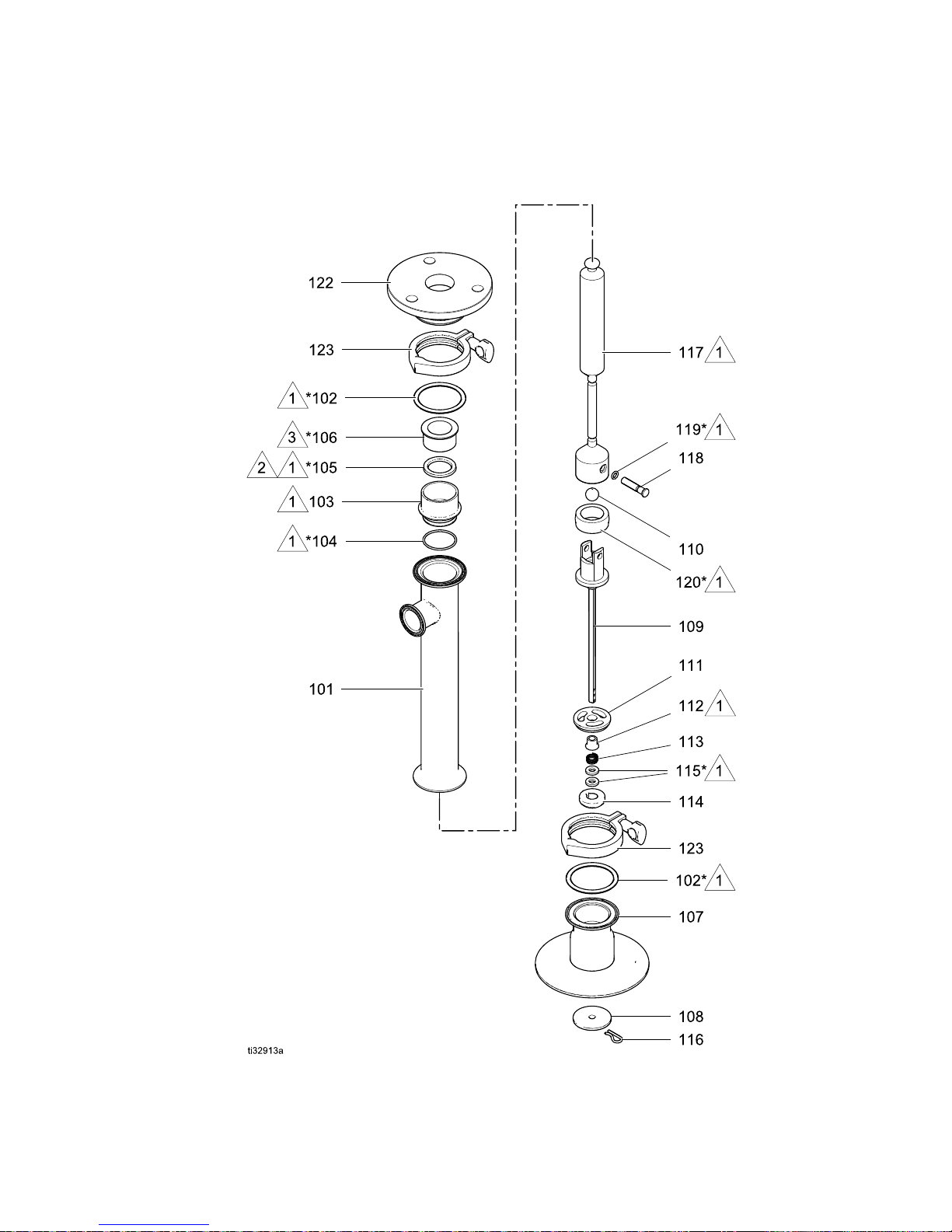
1. Release the upper clamp (123) holding the
displacement pump to the tie rod plate (122).
2. Slide the pump down from the air motor. Tilt the
pump and pull the displacement rod (117) out of
the coupler (C). Remove the gasket (102).
Note: Be careful not to scratch the displacement
rod.
PROTECTIVE EQUIPMENT
Figure 1 Remove displacement pump.
Disassemble the Pump
Note: Pump Repair Kit 24G550 is available.
Purchase the kit separately. Kit parts are
marked with an * in the parts section. See
Priming Piston Displacement Pump Model 25M906,
25M906C31, page 9 .
1. Remove the retaining pin (116) from the
connecting rod (109). Slide off the priming piston
(108).
2. Release the lower clamp (123) to remove the
intake valve housing (107) from the pump
cylinder (101). Remove the gasket (102).
3. Remove the poppet (114), spring (113), and
valve stop (111) off the connecting rod (109).
4. Remove the bearing (112) from the center of the
valvestop(111).
5. Remove the packings (115) from the cen
the poppet (114).
ter of
3A5564A 5
Figure 2 Remove priming piston.
6. Push the displacement rod (117) out through the
bottom of the cylinder (101).
Page 6
Priming Piston S
ervice
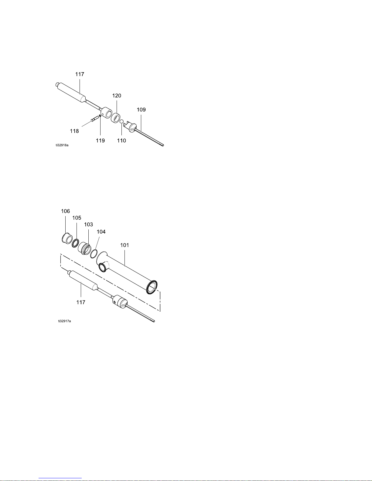
7. Remove the retaining pin (118), o-ring (119), and
ball (110). Pull the connecting rod (109) from the
displacement rod (117). Remove the seal (120).
Figure 3 Di
8. Remove the
of the cyli
packing (1
9. Clean and
Cleaning
necessar
Figure 4 Remove packing housing.
sassemble piston valve.
packing housing (103) from the top
nder (101). Remove the bearing (106),
05), and o-ring (104).
inspect all parts. Refer to
, page 4 . Replace the parts as
y.
Reassemble Af
Note: Any damaged parts must be replaced.
Note: Lubrica
piston seals w
lubricant.
1. Install the v-block packing (105) and bearing
(106) in the packing housing (103). The lips of
the packing must face down into the housing,
and the lip of the bearing must face up. Install
the o-ring (104) on the outside of the housing.
2. Install the seal (120) on the piston valve housing
at the top of the connecting rod (109). Place
the ball (110) on the seat of the housing. Install
the displacement rod (117) over the top of the
connecting rod so the holes in both parts align.
Secure with the retaining pin (118) and o-ring
(119).
3. Lubricate and place the packing housing (103) in
the top of the cylinder.
4. Lubricate and slide the displacement rod (117)
up through the cylinder so it protrudes from the
packing housing (103).
5. Lubricate and install the packings (115) into the
center of the poppet (114).
6. Lubricate and install the bearing (112) into the
center of the valve stop (111).
7. Slide the valve stop (111), spring (113), and
poppet (114) onto the connecting rod (109).
8. Install the gasket (102) and the intake valve
housing (107). Secure the housing (107) to the
cylinder (101) with the clamp (123).
9. Install the priming piston (108) and retaining pin
(116) on the connecting rod (109).
10. Slide the displacement rod (117) into the coupler.
Then, attach the clamp (123) to hold the pump
to the motor base.
te the o-rings, throat packings, and
ith appropriate waterproof sanitary
ter Cleaning
6 3A5564A
Page 7

Parts
Complete Pump Models
25M912
25M912C31
Parts
Apply PT
1
Hand tighten only.
2
Apply sanitary lubricant to ease
assembly.
3
Apply medium-strength (blue)
4
thread locker.
Apply an appropriate
medium-strength thread locker
5
on the nut (13) every time it
is installed to prevent it from
coming loose during operation.
Torque to 30-36 ft-lb (41–49
N-m). Do not over tighten.
FE tape to threads.
3A5564A
7
Page 8

Kits
Complete Pump
Ref. Part
1
2
3 16A938
4 16A947
5
6
7
8 118134
10
11
12 165053
13
15▲ 17W547 LABEL, warning, not shown 1
21
22
23 166702
24G785 MOTOR, SaniForce; 3.5 in; see manual 3A1211
25M906 EN 10204, type 2.1
25M906C31
102216 NUT, lock, 5/8-11, sst 3
16G464 SHIELD, upper; includes grommets (Ref. 21)
16G465 SHIELD, lower; includes fasteners (Ref. 8) and grommets (Ref. 21)
24G862 FITTING, air inlet, 1/2 npt, includes Ref. 23
16C946 FITTING, 3/4 npt
16C306
—
16G084 FITTING, air inlet, 1/2 npt
Model 25M912, 25M912C31
Description
DISPLACEMENT PUMP:
EN 10204, type 3.1
COUPLER
TIE ROD, 7 in. (178 mm) between shoulders
SCREW, cap; M8 x 1.25, sst
O-RING, PTFE
NUT, hand 1
GROMMET;
O-RING, air inlet, buna-n, included with Ref. 10
see Kits
Qty.
1
1
1
3
1
1
4
1
1
1
6
1
1
▲ Replacement Danger and Warning labels, tags, and cards are available at no cost.
‡
These parts are not used with Model 25D363.
Kits
Gromm
Ref.
21a*
21b
21c
* Order Kit 16H925 for qty. 3 of the piston rod grommet.
et Kit 16G628
Part Description
—
—
—
GROM
pist
GROMMET, air fitting
GROMMET, tie rod
MET, air motor
on rod
Qty.
1
2
3
8 3A5564A
Page 9
Priming Piston Displacement Pump Model 25M906, 25M906C31
Priming Pisto
25M906C31
n Displacement Pump Model 25M906,
3A5564A 9
Page 10

Priming Piston Displacement Pump Model 25M906, 25M906C31
Priming Piston Displacement Pump Model 25M906, 25M906C31
Ref. Part
101 902980
102*
103 180918
104*
105*
106*
107
108 195214
109
110 103462
111 195215
112*
113*
166117
166119
180238
605752
17S673 HOUSING, inlet valve
16C195 ROD, connecting
604016
501095
Description
CYLINDER, pum
GASKET, 2 1/2 i
buna-n
HOUSING, packing
CYLINDER SEAL, buna-n
THROAT PACKING, buna-n
BEARING, sleeve
PISTON, priming
BALL, 3/4 in. (19 mm),
stainless steel
STOP, inlet valve
BEARING, priming piston
SPRING, ball check
p
n. (64 mm),
Qty.
Ref. Part
114 604018
1
2
115*
1
116 604008 PIN, retaini
1
117 902983
1
118 169845 PIN, retain
1
119*
1
120*
1
122 16A945 PLATE, tie
1
123 620223
1
130 172687
1
* Parts included in Repair Kit 24G550.
1
1
603778
167972
167971
Description
POPPET, inlet
PACKING, inle
neoprene
ROD, displacement
O-RING
SEAL, piston, neoprene
CLAMP, 2 1/2 in. (64 mm)
TAG, Instruction, not shown
valve
tvalve,
ng, priming piston
er
rod
Qty.
1
2
1
1
1
1
1
1
2
1
10 3A5564A
Page 11

Product Dimensions
Product Dimensions
Model A
in. (cm)
25D363
* Add 2.5 in. (6.3 cm) to allow for full extension of the priming piston rod.
3A5564A
40.1 (102)* 20.6 (52)* 16.0 (41)* 2.5 (6.4)
B
in. (cm)
C
in. (cm)
D
in. (cm)
11
Page 12
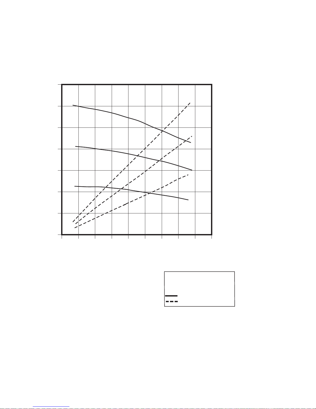
Performance cha
rt
Performance c
0
700
(4.8, 48)
600
(4.1, 41)
500
(3.4, 34)
400
(2.8, 28)
300
(2.1, 21)
200
(1.4, 14)
A
B
C
hart
Cycles per Minute
15 30
45 60
A
B
C
35
(1.0)
30
(0.85)
25
(0.71)
20
(0.57)
15
(0.42)
10
(0.28)
/min)
3
Air Flow scfm (m
100
Fluid Outlet Pressure psi (MPa, bar)
(0.7, 7)
0
0
1.0
(3.8)
2.0
(7.6)
Fluid Flow gpm (lpm) tested in No. 10 weight oil
3.0
(11.4)
5
(0.14)
4.0
(15.1)
A = 100 psi (0.7 MPa, 7 bar)
B = 70 psi (0.5 MPa, 5 bar)
C = 40 psi (0.3 MPa, 3 bar)
= fluid flow
= air consumption
2
1
3A5564A
Page 13

Technical Data
Technical Data
Maximum Fluid
Maximum Air Inlet Pressure
Maximum Recommended Pump Speed 60 cycles/min, 4 gpm (15 liters/min) delivery
Air Consumption
Pump Cycle
Ratio 6:1
Maximum Fluid Temperature
Maximum Ambient Temperature (Air
Motor)
Air Inle
Air Exhaust
Fluid Inlet Type
Fluid Outlet 1-1/2 in. (3.8 cm) Tri-clamp®
Weight
Wetted Parts
Sound data
t
Working Pressure
s per Gallon (3.8 Liters)
und power*
So
650 psi (4.5 MPa, 44.8 bar)
100 psi (0.7 M
Pa, 6.9 bar)
See Performance Chart
13.3
250°F (12
120°F (49°C)
1/2 npt (f)
3/4 npt
2.3 in (5.8 cm) Priming Piston with flange for 6 in. (15.2 cm) Clamp
35 lb
316 Stainless Steel, Buna-N, Polychloroprene, Nitrile, Nylon,
UHMWPE. Certain models have PTFE packings.
78.5 dBA
1°C)
(m)
(16 kg)
Sound pressure**
* Sound power at 70 psi (0.48 MPa, 4.8 bar), 20 cpm. Sound power measured per ISO-9614-2.
** Sound pressure was tested 3.28 feet (1 m) from equipment.
71.6 dBA
3A5564A 13
Page 14

Graco Standard Warranty
Graco warrants all equipment referenced in this document which is manufactured by Graco and bearing its
name to be free from defects in material and workmanship on the date of sale to the original purchaser for
use. With the exception of any special, extended, or limited warranty published by Graco, Graco will, for a
period of twelve months from the date of sale, repair or replace any part of the equipment determined
by Graco to be defective. This warranty applies only when the equipment is installed, operated and
maintained in accordance with Graco’s written recommendations.
This warranty does not cover, and Graco shall not be liable for general wear and tear, or any malfunction,
damage or wear caused by faulty installation, misapplication, abrasion, corrosion, inadequate or improper
maintenance, negligence, accident, tampering, or substitution of non-Graco component parts. Nor shall
Graco be liable for malfunction, damage or wear caused by the incompatibility of Graco equipment
with structures, accessories, equipment or materials not supplied by Graco, or the improper design,
manufacture, installation, operation or maintenance of structures, accessories, equipment or materials
not supplied by Graco.
This warranty is conditioned upon the prepaid return of the equipment claimed to be defective to an
authorized Graco distributor for verification of the claimed defect. If the claimed defect is verified, Graco
will repair or replace free of charge any defective parts. The equipment will be returned to the original
purchaser transportation prepaid. If inspection of the equipment does not disclose any defect in material
or workmanship, repairs will be made at a reasonable charge, which charges may include the costs of
parts, labor, and transportation.
THIS WARRANTY IS EXCLUSIVE, AND IS IN LIEU OF ANY OTHER WARRANTIES, EXPRESS OR
IMPLIED, INCLUDING BUT NOT LIMITED TO WARRANTY OF MERCHANTABILITY OR WARRANTY
OF FITNESS FOR A PARTICULAR PURPOSE.
Graco’s sole obligation and buyer’s sole remedy for any breach of warranty shall be as set forth above.
The buyer agrees that no other remedy (including, but not limited to, incidental or consequential damages
for lost profits, lost sales, injury to person or property, or any other incidental or consequential loss) shall
be available. Any action for breach of warranty must be brought within two (2) years of the date of sale.
GRACO MAKES NO WARRANTY, AND DISCLAIMS ALL IMPLIED WARRANTIES OF
MERCHANTABILITY AND FITNESS FOR A PARTICULAR PURPOSE, IN CONNECTION WITH
ACCESSORIES, EQUIPMENT, MATERIALS OR COMPONENTS SOLD BUT NOT MANUFACTURED BY
GRACO. These items sold, but not manufactured by Graco (such as electric motors, switches, hose, etc.),
are subject to the warranty, if any, of their manufacturer. Graco will provide purchaser with reasonable
assistance in making any claim for breach of these warranties.
In no event will Graco be liable for indirect, incidental, special or consequential damages resulting from
Graco supplying equipment hereunder, or the furnishing, performance, or use of any products or other
goods sold hereto, whether due to a breach of contract, breach of warranty, the negligence of Graco, or
otherwise.
FOR GRACO CANADA CUSTOMERS
The Parties acknowledge that they have required that the present document, as well as all documents,
notices and legal proceedings entered into, given or instituted pursuant hereto or relating directly or
indirectly hereto, be drawn up in English. Les parties reconnaissent avoir convenu que la rédaction du
présente document sera en Anglais, ainsi que tous documents, avis et procédures judiciaires exécutés,
donnés ou intentés, à la suite de ou en rapport, directement ou indirectement, avec les procédures
concernées.
Graco Information
For the latest information about Graco products, visit www.graco.com.
For patent information, see www.graco.com/patents.
To place an order, contact your Graco Distributor or
Phone: 612-623-6921 or Toll Free: 1-800-328-0211 Fax: 612-378-3505
All written and visual data contained in this document reflects the latest product information available at the time of publication.
Graco reserves the right to make changes at any time without notice.
Original Instructions. This manual contains English. MM 3A5564
International Offices: Belgium, China, Japan, Korea
GRACO INC. AND SUBSIDIARIES • P.O. BOX 1441 • MINNEAPOLIS MN 55440-1441 • USA
Copyright 2017, Graco Inc. All Graco manufacturing locations are registered to ISO 9001.
call to identify the nearest distributor.
Graco Headquarters: Minneapolis
www.graco.com
Revision A, March 2018
 Loading...