

Page 1
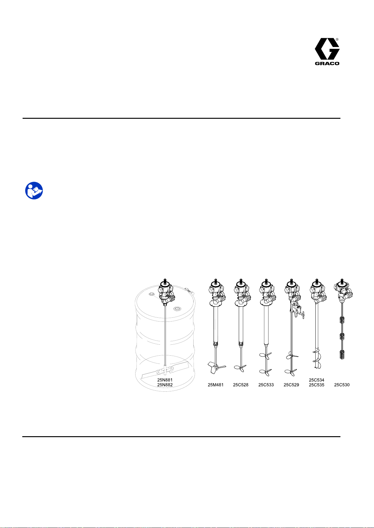
Instructions/Parts
Air
Air Air
Radial
Radial Radial
paints
paints paints
70psi(0.5MPa,5bar)Maximum
RecommendedWorkingPressure
Seepage3formodelpartnumbersand
approvalsinformation.
Driven
- --Driven Driven
piston,
piston, piston,
and
coatings.
and and
coatings. coatings.
Important
Important Important
Readallwarningsandinstructionsinthismanualandinyour
associatedcomponentmanualsbeforeusingtheequipment.Save
theseinstructions.
Agitators
Agitators Agitators
pneumatic
pneumatic pneumatic
Safety
Safety Safety
motor
motor motor
For
professional
For For
professional professional
Instructions
Instructions Instructions
3A4792C
EN
driven
driven driven
agitators
agitators agitators
use
use use
for
maintaining
for for
maintaining maintaining
only.
only. only.
suspension
suspension suspension
and
even
and and
mixing
even even
mixing mixing
industrial
in ininindustrial industrial
PROVENQUALITY.LEADINGTECHNOLOGY.
Page 2

Contents
Contents Contents
Models...............................................................3
RelatedManuals................................................3
Warnings...........................................................4
Installation..........................................................6
AirRegulatorandMufers............................7
Agitator.......................................................8
Grounding...................................................9
AirLineAccessories.....................................11
AirRequirements.........................................11
Operation...........................................................12
AgitatorOperation........................................12
FindingtheProperAgitatorSpeed................12
PressureReliefProcedure............................12
Maintenance......................................................13
GreasingtheAirMotor.................................13
AirMotorMufer..........................................13
CleaningtheShaft.......................................13
Service..............................................................14
RemovingtheAirMotor................................14
AligningtheOutletHousing—25C534,
25C535Only..................................15
InspectingtheShaftandAgitatorBlades—
Model25C530Only........................15
Parts..................................................................16
Model25C528.............................................16
Model25C533.............................................17
Model25M481.............................................18
Model25C529.............................................19
Models25C534and25C535........................20
Model25C530.............................................21
Models25N881and25N882........................22
Accessories........................................................22
SensorKit25C373.......................................22
Dimensions........................................................23
MountingHoleLayout.........................................25
AirConsumption.................................................25
TechnicalSpecications......................................26
CaliforniaProposition65...............................27
2
3A4792C
Page 3

Models
Models
Models Models
Part
No.
Part Part
No. No.
25C528
25C533
25M481
25C534
25C535
Description
Description Description
StainlessSteelDirectDrive,
30/55Gallon,
OneSS5.5"Propeller
CarbonSteelDirectDrive,
30/55Gallon,
TwoAlum5.5"Propellers
StainlessSteelDirectDrive,
30/55Gallon,
OneSS8"Impeller
StainlessSteelDirectDrive,
Helix,
BungMount
CarbonSteelDirectDrive,
Helix,
BungMount
Recommended
Recommended Recommended
Agitator
Agitator Agitator
Rotation
Rotation Rotation
Clockwise
Clockwise
Clockwise
2575
Clockwise
Clockwise
2575 2575
Approvals
Approvals Approvals
1/2
G
II IIII1/2 1/2
G G
Ex
IIB
T4
Ex Ex
h hhIIB IIB
IECEx
IECEx IECEx
ITS17ATEX1001809
ITS17ATEX1001809 ITS17ATEX1001809
0 00°C CC≤Tamb Tamb
Ga/Gb
T4 T4
Ga/Gb Ga/Gb
ETL
17.0019
ETL ETL
17.0019 17.0019
Tamb
50
C
≤50 50
°C C
StainlessSteelDirectDrive,
25C530
25N881
25N882
25C529
25C765
Related
Related Related
ManualNumberTitle
306287
55Gallon,
BungMount,
ExpandingBlade
In-Drum,
1.5”BungMount
In-Drum,
2”BungMount
CarbonSteelDirectDrive,
55Gallon,
SideMount,
TwoAluminum5.5"
Propellers
Kit,MotorwithAirRegulator
(toreplacedrivemotoron
existingagitators)
Manuals
Manuals Manuals
ElevatorsandPumpSupports
Counter
Clockwise
Clockwise
Ex
IIB
T4
II IIII2 22G GGEx Ex
Clockwise
Clockwise
II IIII2 22G GGEx Ex
h hhIIB IIB
Ex
h hhIIB IIB
Gb
T4 T4
Gb Gb
IIB
T4
Gb
T4 T4
Gb Gb
308466
3A5050MotorRepairManual
StainlessSteel,PassivatedDrumCovers
3A4792C3
Page 4
Warnings
Warnings
Warnings Warnings
Thefollowingwarningsareforthesetup,use,grounding,maintenance,andrepairofthisequipment.Theexclamation
pointsymbolalertsyoutoageneralwarningandthehazardsymbolsrefertoprocedure-specicrisks.Whenthese
symbolsappearinthebodyofthismanual,referbacktotheseWarnings.Product-specichazardsymbolsand
warningsnotcoveredinthissectionmayappearthroughoutthebodyofthismanualwhereapplicable.
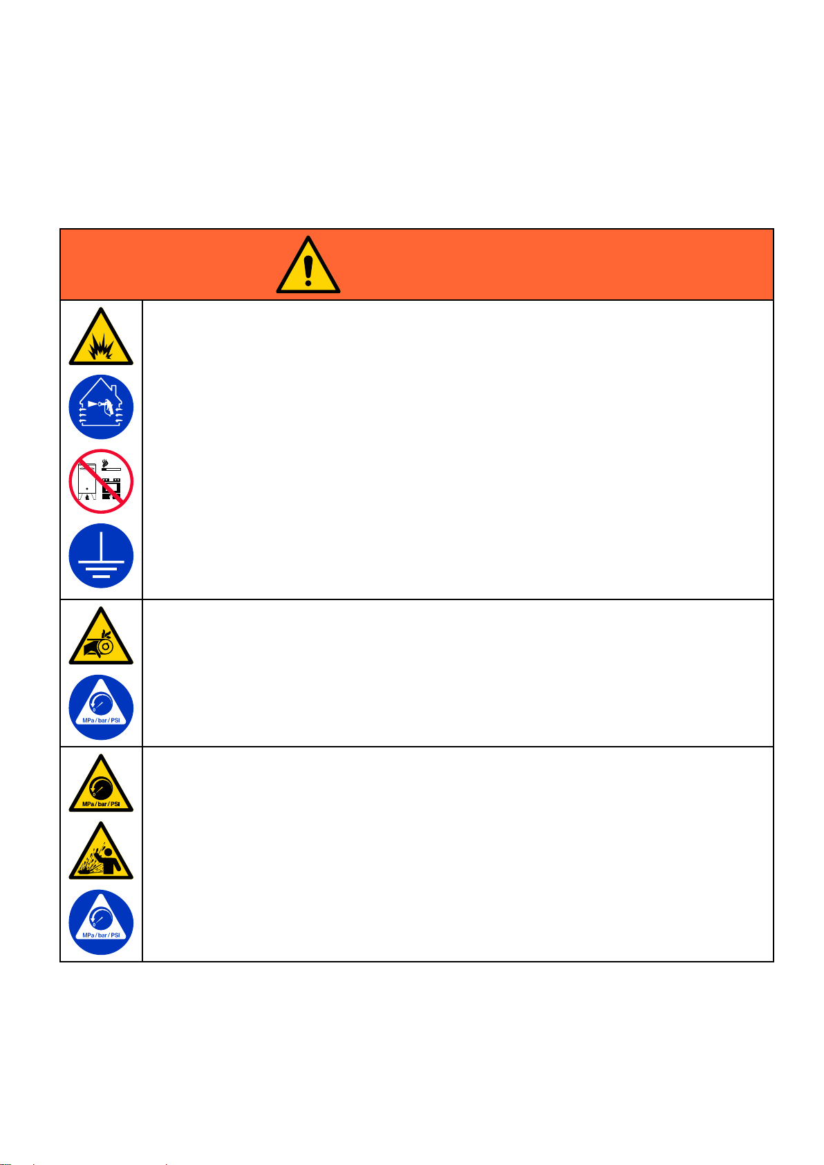
WARNING
WARNING WARNING
FIRE
AND
FIRE FIRE
Flammablefumes,suchassolventandpaintfumes,inwork work
solventowingthroughtheequipmentcancausestaticsparking.Tohelppreventreandexplosion:
•Useequipmentonlyinwellventilatedarea.
•Eliminateallignitionsources;suchaspilotlights,cigarettes,portableelectriclamps,andplastic
dropcloths(potentialstaticarc).
•Groundallequipmentintheworkarea.SeeGrounding Grounding
•Neversprayorushsolventathighpressure.
•Keepworkareafreeofdebris,includingsolvent,ragsandgasoline.
•Donotplugorunplugpowercords,orturnpowerorlightswitchesonoroffwhenammable
fumesarepresent.
•Useonlygroundedhoses.
•Holdgunrmlytosideofgroundedpailwhentriggeringintopail.Donotusepaillinersunlessthey
areantistaticorconductive.
Stop
•Stop Stop
youidentifyandcorrecttheproblem.
•Keepaworkingreextinguisherintheworkarea.
MOVING
MOVING MOVING
EXPLOSION
AND AND
EXPLOSION EXPLOSION
operation
operation operation
PARTS
PARTS PARTS
immediately
immediately immediately
HAZARD
HAZARD HAZARD
HAZARD
HAZARD HAZARD
work
area
area area
canigniteorexplode.Paintor
Grounding
ifstaticsparkingoccursoryoufeelashock,Donotuseequipmentuntil
instructions.
Movingpartscanpinch,cut,oramputatengersandotherbodyparts.
•Keepclearofmovingparts.
•Donotoperateequipmentwithprotectiveguardsorcoversremoved.
•Donotwearlooseclothing,jewelry,orlonghairwhileoperatingequipment.
•Equipmentcanstartwithoutwarning.Beforechecking,moving,orservicingequipment,followthe
Pressure
Pressure Pressure
PRESSURIZED
PRESSURIZED PRESSURIZED
Fluidfromtheequipment,leaks,orrupturedcomponentscansplashintheeyesoronskinand
causeseriousinjury.
•FollowthePressure Pressure
checking,orservicingequipment.
•Tightenalluidconnectionsbeforeoperatingtheequipment.
•Checkhoses,tubes,andcouplingsdaily.Replacewornordamagedpartsimmediately.
Relief
Procedure
Relief Relief
Procedure Procedure
EQUIPMENT
EQUIPMENT EQUIPMENT
Pressure
anddisconnectallpowersources.
HAZARD
HAZARD HAZARD
Relief
Procedure
Relief Relief
Procedure Procedure
whenyoustopspraying/dispensingandbeforecleaning,
4
3A4792C
Page 5
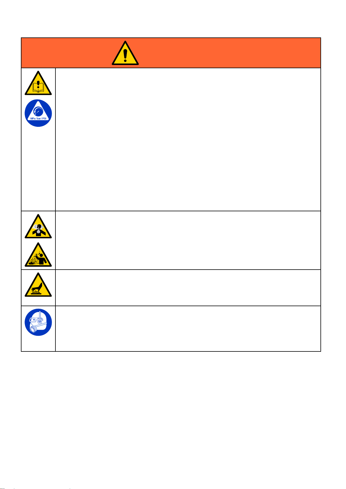
WARNING
WARNING WARNING
EQUIPMENT
EQUIPMENT EQUIPMENT
Misusecancausedeathorseriousinjury.
•Donotoperatetheunitwhenfatiguedorundertheinuenceofdrugsoralcohol.
•Donotexceedthemaximumworkingpressureortemperatureratingofthelowestratedsystem
component.SeeTechnical Technical
•Useuidsandsolventsthatarecompatiblewithequipmentwettedparts.SeeTechnical Technical
Specications
Specications Specications
completeinformationaboutyourmaterial,requestSDSfromdistributororretailer.
•Donotleavetheworkareawhileequipmentisenergizedorunderpressure.
•TurnoffallequipmentandfollowthePressure Pressure
•Checkequipmentdaily.Repairorreplacewornordamagedpartsimmediatelywithgenuine
manufacturer’sreplacementpartsonly.
•Donotalterormodifyequipment.Alterationsormodicationsmayvoidagencyapprovalsand
createsafetyhazards.
•Makesureallequipmentisratedandapprovedfortheenvironmentinwhichyouareusingit.
•Useequipmentonlyforitsintendedpurpose.Callyourdistributorforinformation.
•Routehosesandcablesawayfromtrafcareas,sharpedges,movingparts,andhotsurfaces.
•Donotkinkoroverbendhosesorusehosestopullequipment.
•Keepchildrenandanimalsawayfromworkarea.
•Complywithallapplicablesafetyregulations.
TOXIC
TOXIC TOXIC
MISUSE
MISUSE MISUSE
FLUID
FLUID FLUID
OR
OR OR
HAZARD
HAZARD HAZARD
Technical
inallequipmentmanuals.Readuidandsolventmanufacturer’swarnings.For
FUMES
FUMES FUMES
Specications
Specications Specications
HAZARD
HAZARD HAZARD
Pressure
inallequipmentmanuals.
Relief
Relief Relief
Technical
Procedure
Procedure Procedure
whenequipmentisnotinuse.
Warnings
Toxicuidsorfumescancauseseriousinjuryordeathifsplashedintheeyesoronskin,inhaled,or
swallowed.
•ReadSafetyDataSheet(SDS)toknowthespecichazardsoftheuidsyouareusing.
•Storehazardousuidinapprovedcontainers,anddisposeofitaccordingtoapplicableguidelines.
BURN
BURN BURN
Equipmentsurfacesanduidthatisheatedcanbecomeveryhotduringoperation.Toavoidsevere
burns:
•Donottouchhotuidorequipment.
PERSONAL
PERSONAL PERSONAL
Wearappropriateprotectiveequipmentwhenintheworkareatohelppreventseriousinjury,including
eyeinjury,hearingloss,inhalationoftoxicfumes,andburns.Protectiveequipmentincludesbut
isnotlimitedto:
•Protectiveeyewear,andhearingprotection.
•Respirators,protectiveclothing,andglovesasrecommendedbytheuidandsolventmanufacturer.
HAZARD
HAZARD HAZARD
PROTECTIVE
PROTECTIVE PROTECTIVE
EQUIPMENT
EQUIPMENT EQUIPMENT
3A4792C5
Page 6
Installation
Installation
Installation Installation
NOTE:Throughoutthemanual,referencenumbers
andlettersinparenthesesrefertocalloutsingures
andthepartsdrawings.
Toreducetheriskofreandexplosion,always
maintainaminimumof1in.(25.4mm)clearance
betweentherotatingagitatorpartsandthe
containertopreventsparksfromcontact.
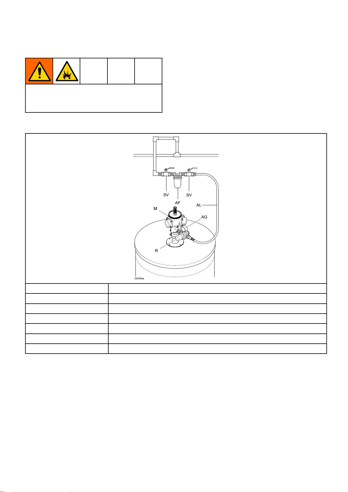
Table
Table Table
Typical
1 11Typical Typical
Installation
Installation Installation
SeeAirLineAccessories,page11forpartsnot
includedinyoursystem.
Reference
SVAirShutoffValve
AFAirLineFilter
MMotor
AL
AGAirPressureGauge
RRegulator
Description
SupplyLine,Air-In
63A4792C
Page 7
Air
Regulator
Air Air
Regulator Regulator
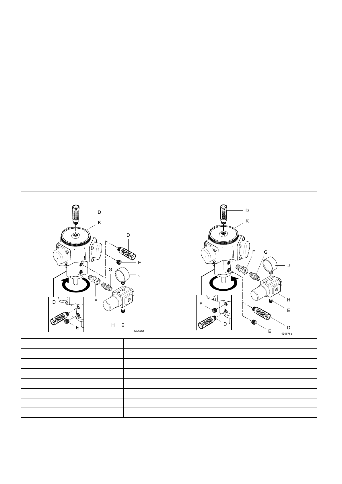
Theairmotoriscapableofoperatinginaclockwise
orcounterclockwisedirection,dependingonwhere
theairregulatorismounted.
•Whentheairregulatorisinstalledinoneofthe
twolowerportsonthemotor,aclockwiserotation
results,asviewedfromthetopofthemotor.
•Wheninstalledoneithersideinoneofthetwo
upperports,acounterclockwiserotationresults.
•Theportoppositetheregulatormustbeplugged
forthemotortooperate.
Theairregulator,mufers,airgauge,nipple
connector,andswivelconnectorarenotfactory
installed.Followthedirectionsbelowtoinstallthese
items:
1.Screwtheswivelconnector(F)intothedesired
port(upperorlower)inthemotor(K).
2.Screwthenippleconnector(G)intotheair
regulator(H)outlet.Notearrowdirectionson
theregulator.
and
Mufers
and and
Mufers Mufers
Installation
3.Attachtheairregulatorbyscrewingitintothe
swivelconnector.
4.Installaplug(E)intheportoppositetheregulator
(thisisnecessaryformotoroperation).
5.Attachtheairgauge(J)byscrewingitintothe
holeinthetopoftheairregulator.
6.Installaplug(E)intheregulatorintheport
oppositetheairgauge.
7.Screwonemufer(D)intothetopofthemotor.
8.Screwthesecondmuferintotheopenporton
thefarsideofthemotorfromtheregulator.
9.Installthethirdmuferintheopenportabove
orbelowtheregulator.Anadditionalttingmay
beneeded(notprovided)tospacetheregulator
fartherawayfromthemotor.
NOTE:
NOTE: NOTE:
butisbenecialforincreasedaircirculationin
humidconditions.Ifathirdmuferisnotused,
theholemustbeplugged(E).
Useofthethirdmuferisnotnecessary,
Clockwise
Clockwise Clockwise
Reference
Reference Reference
D
Agitator
Agitator Agitator
Letter
Letter Letter
Rotation
Rotation Rotation
Description
Description Description
Mufers
Counterclockwise
Counterclockwise Counterclockwise
Agitator
Agitator Agitator
Rotation
Rotation Rotation
EPlugs
F
G
HAirregulator
JAirgauge
KAirmotor
3A4792C
Swivelconnector
Nippleconnector
7
Page 8
Installation
Agitator
Agitator Agitator
Positiontheairmotorsotheairlineeasilyattaches
totheairregulatorinletwithoutobstructinganyother
systemcomponents.
Toreducetheriskofreandexplosion,always
maintainaminimumof1in.(25.4mm)clearance
betweentherotatingagitatorpartsandthe
containertopreventsparksfromcontact.
Models
Models Models
1.Markanddrillholesinthecovertomountthe
2.Installtheagitatorinthecoveroftheuid
3.Positiontheairmotorsotheairlineeasily
4.Boltinplace(mountingboltsnotincluded).
Model
Model Model
Mounttheagitatorontheedgeofthedrumortank
andsecurelytightentheclampscrew(6).Squeeze
theendoftheretainer(17)tosetinplace.See
Model25C529,page19.
Toadjusttheangleoftheagitatorinthedrum,loosen
thebracketscrew(4),andpositiontheairmotorso
theairlineeasilyattachestotheairregulatorinlet
withoutobstructinganyothersystemcomponents.
25C528,
25C528, 25C528,
agitator.SeeMountingHoleLayout,page25for
dimensions.
supplytankwiththegasket(29)inplace.See
Model25C528,page16,Model25C533,page17,
andModel25M481,page18.
attachestotheairregulatorinletwithout
obstructinganyothersystemcomponents.
25C529
25C529 25C529
25C533,
25C533, 25C533,
and
25M481
and and
25M481 25M481
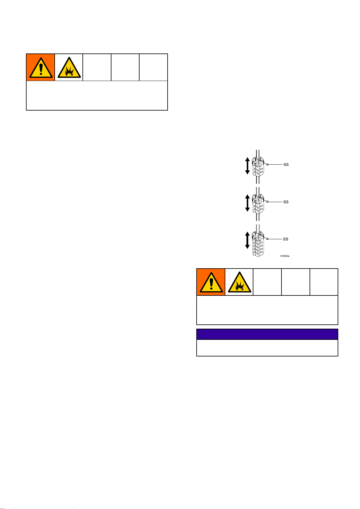
Duetovariabilityindrumheights,thelowestsetof
bladesmaycontactthebottomofthedrum.Ifthe
bungadapter(4)doesnotfullyseat,orifresistance
isfeltwheninstallingtheagitator,movetheblades
uptheshaft.
Tomovetheblades,loosenthesetscrews(SS)in
thecouplerandslidetheassemblyupordowntothe
desiredposition.Thesetscrewmustalwaysremain
onthetop,withthebladeshangingdown,sothe
bladesareabletopassintoandoutofthebunghole.
Figure1AdjustableBladeAssemblies
Models
Models Models
Installtheagitatorinthecontainercoverbyscrewing
thehelix(5)throughthedrumbungholeand
screwingtheagitatorhousing(3)intothebung
hole.Torquethesocketheadscrew(2)to150–170
in-lbs(17–19N•m).Torquethehexheadcap
screw(14)to80–100in-lbs(9–11N•m).See
Models25C534and25C535,page20.
Positiontheairmotorsotheairlineeasilyattaches
totheairregulatorinletwithoutobstructinganyother
systemcomponents.
Model
Model Model
Toinstalltheagitatorinthecontainercover,lowerthe
shaft(2)withfoldingbladeassemblies(5,6)through
thedrumbunghole,thenscrewthebungadapter(4)
intothebunghole.SeeModel25C530,page21.
25C534
25C534 25C534
25C530
25C530 25C530
and
25C535
and and
25C535 25C535
Toreducetheriskofreandexplosion,when
usingamodieddrum,checkthatthereisno
interferencebetweenthebaseofthedrumandthe
shaftoftheagitatortoavoidsparksfromcontact.
NOTICE
NOTICE NOTICE
Keeptheagitatortightlymountedtothedrumbung
topreventdamagetothethreadsfromvibration.
Angled
Angled Angled
only
only only
Iftheagitatorisusedonadrumwithanoff-center
bungandthebladescontactthesideofthedrum,the
angledadapter16H294mustbeused.
1.Threadthelockingring(28)ontotheangled
Adapter
Adapter Adapter
adapter(27)byhand,asfarasitwillgo.
16H294
16H294 16H294
—
Model
— —
Model Model
25C530
25C530 25C530
83A4792C
Page 9
Installation
2.Threadtheangledadapterintothebunguntil
itbottomsout,thenbackitoutuntilthewidest
portionoftheadaptertopispointingjusttothe
leftofdrumcenter.
Figure2AngledAdapterJustLeftofCenter
3.Turndownthelockingringuntilitcontactsthe
drum.Useanappropriatelysizedpipewrenchor
adjustablewrenchtotightentheadapteruntilthe
widestportionoftheadaptertopisinlinewiththe
drumcenter.
Models
Models Models
25N881
25N881 25N881
and
25N882
and and
25N882 25N882
Grounding
Grounding Grounding
Theequipmentmustbegroundedtoreducethe
riskofstaticsparking.Staticsparkingcancause
fumestoigniteorexplode.Toreducetherisk
ofstaticsparking,themountingcoverandall
electricallyconductiveobjectsordevicesinthe
sprayareamustbeproperlygrounded.
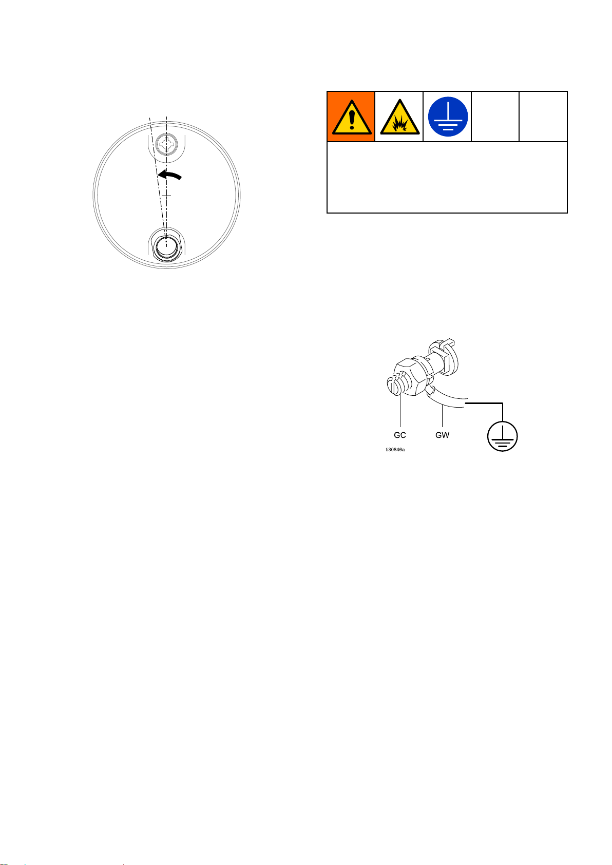
Agroundwireandclamparenotincluded.Fora
groundwireandclamp,orderpartnumber237569.
Togroundtheagitator,dothefollowing:
For
models
•For For
models models
Connectoneendofthegroundwire(GW)tothe
groundconnector(GC)ontherimofthedrum
cover.Connecttheotherendofthegroundwireto
atrueearthground.
25C528,
25C528, 25C528,
25C533,
25C533, 25C533,
and
25M481:
and and
25M481: 25M481:
SeeModels25N881and25N882,page22.
1.Determinetheagitatorshaftsize:7/16"(11.1
mm)or1/2"(12.4mm)square.Determinethe
sizeoftheshaftadapter(9).Selectthesizeby
placingtheadaptersontothebuilt-inagitator
shaftinsidethedrum.Usethesmallestadapter
thatwillt.Thereshouldonlybeasmallamount
ofslipbetweentheadapternutandtheshaft.
2.Attachtheshaftadapter(9)totheatsideof
themotorshaftclosetothebottomofthemotor.
Tightenthesetscrew(12)securelyto8–9ft-lbs
(11–12N•m).NOTE:Thereisapproximately1/2"
(12mm)ofadjustmenttraveloftheadaptershaft
onthemotorshaftifneededforlateradjustment.
3.Torquethesocketheadscrew(8)to12.5–14
ft-lbs(17–19N•m).
4.Placethethreadedhousingadapter(6)ontothe
motorplate(7)andsecurewithwashers(13)and
screws(11).Torqueto8–9ft-lbs(11–12N•m).
5.Aligntheadapternuttoengagethebuilt-inshaft
inthe55-gallondrum.
6.Slowlyscrewtheunitontothethreadsonthe
centerbungttingofthe55-gallondrum.Secure
tightlysothemotordoesnotrotateinthebung.
Figure3GroundConnector-Models25C528,
25C533,and25M481
Motor
Motor Motor
Motorreplacementkit25C765isadrop-in
replacementforrotaryvaneairmotorPN101140.
Onpage16—Parts,RefNo.1liststheitems
includedwiththekit.Usetheagitatormanualmotor
replacementprocedureorpartspagediagramto
installthenewmotor.
Replacement
Replacement Replacement
Kit
25C765
Kit Kit
25C765 25C765
3A4792C9
Page 10

Installation
For
models
•For For
models models
25N881,
25N881, 25N881,
groundwire(GW)totheagitatorgroundconnector
(GC).Connecttheotherendofthegroundwireto
atrueearthground.
Figure4GroundConnector-Model25C529
25C529,
25C529, 25C529,
and
25N882:
and and
25N882: 25N882:
25C530,
25C530, 25C530,
Connectoneendofthe
25C534,
25C534, 25C534,
25C535,
25C535, 25C535,
Figure6GroundConnector-Models25C534,
25C535
Figure5GroundConnector-Model25C530
Figure7GroundConnector-Models25N881,
25N882
103A4792C
Page 11

Installation
Air
Line
Air Air
Line Line
Accessories
Accessories Accessories
Air
Requirements
Air Air
Requirements Requirements
Installthefollowingaccessoriesintheordershown
below,usingadaptersasnecessary.
Air
Shut
off
Air Air
Shut Shut
Ableed-typemasterairshutoffvalve(A)formounting
location)isolatestheairlinecomponentsfor
servicing.Anairshutoffvalveshouldbeinstalledin
thesupplylineandusedtostopandstarttheagitator.
Ifthevalveisinstalled,youdonotneedtosetthe
agitatorspeedeachtimeitisused.
Orderbleed-typeairshutoffvalvesusingthepart
numberslistedbelow:
Table
Table Table
2 22Bleed Bleed
Part
No.
110223
110223 110223
110224
110224 110224
110225
110225 110225
110226
110226 110226
113163
113163 113163
107142
107142 107142
107141
107141 107141
Valve
- --off off
Valve Valve
Bleed
Type
Outletnpt
1/4(fxf)
3/8(fxf)
1/2(fxf)
3/4(fxf)
1/2(mxf)
3/4(mxf)
Shutoff
- --Type Type
Shutoff Shutoff
Inlet/
1(fxf)
Valves
Valves Valves
MaxWPR
psibarMPa
25017.21.7Brass
25017.21.7Brass
25017.21.7Brass
25017.21.7Brass
25017.21.7Brass
25017.21.7Brass
25017.21.7Brass
Mate-
Theairmotordoesnotrequirelubricatedair.See
AirConsumption,page25forrequirements.
Connectthesupplyairtotheinletsideoftheair
regulator.
rial
Figure8SupplyAirHoseConnection
Air
Line
Air Air
Airlineltersremoveharmfuldirt,moisture,andoil
fromthecompressedairsupply.Orderpart106148
for3/8nptor106149for1/2npt.
Installanairlinelter(AF)toremovecontaminants
suchasdirt,moisture,andoilfromthecompressed
airsupply.Airlinelters(AF)removeharmfuldirt
andmoisturefromthecompressedairsupply.Order
part106148for3/8nptor106149for1/2npt.See
Installation,page6.
Filter
Line Line
Filter Filter
3A4792C
11
Page 12

Operation
Operation
Operation Operation
Personalinjury,suchassplashingintheeyes,
mayresultfrompressureinthetank.Alwaysfollow
thePressureReliefProcedure,page12before
openingthetankcoverorllport.
Personalinjuryorequipmentdamagemayresult
fromlifting/fallingheavyequipment.Toavoid
personalinjuryorequipmentdamage:
•Donotliftthedrumcoverandagitatorwithout
properassistance.
•Donotwalkorstandbeneatharaisedelevator.
Agitator
Agitator Agitator
1.Starttheagitatorbyopeningtheairshutoffvalve
(SV).Regulatethespeedwiththeairregulator
knob(R).
2.Operatetheagitatorcontinuouslywhensupplying
paintsorotheruidstothesystem.
3.Stoptheagitatorbyclosingtheairshutoffvalve
orbyreducingpressurewiththeairregulator
knob.
Operation
Operation Operation
useashakerorsomeotherdevicetothoroughly
agitatetheuidbeforeinstallingandoperatingthe
agitator.
Belowisageneralproceduretondthesuggested
agitatorspeed.Consultyourmaterialsupplier
forspecicrecommendationsonrecommended
agitationspeeds.
1.Besuregroundwireisattached.See
Grounding,page9.
2.Filltheuidsupplycontainertoabout3or4
inches(75to100mm)abovetheagitatorblade.
3.Opentheairshutoffvalve(SV).
4.Starttheagitatorbygraduallyturningtheair
regulatorknob(R)toincreaseairpressureuntila
vortexbeginstoforminthepaint.
5.Reducethespeedslightly,thenlltheuid
container.
Whenthecontainerisfullavortexshouldnotbe
seen.Materialshouldonlybemovingatafast
enoughspeedtoensureadequatemixing.
6.Operatetheagitatorcontinuouslywhilesupplying
paintsorotheruidstothesystem.
Pressure
Pressure Pressure
Relief
Relief Relief
Procedure
Procedure Procedure
Finding
Finding Finding
Toavoiddamagingtheequipment,donotoperate
theagitatoratahighspeedforalongperiodof
time.Excessiveagitatorspeedcancausefoaming
ofuid(makingtheuidunusable),vibration,and
increasedwearonparts.Onlyagitatetheuid
enoughtomaintainevenmixing.
Agitatorsareusedtokeepsolidsinsuspension,
whichassistsinkeepingsolidsfromcloggingthe
siphontube.Ifsolidshavesettledinthecontainer,
the
Proper
the the
Proper Proper
Agitator
Agitator Agitator
NOTICE
NOTICE NOTICE
Speed
Speed Speed
Thisequipmentstayspressurizeduntilpressure
ismanuallyrelieved.Tohelppreventserious
injuryfromsplashinguidandmovingparts,follow
thePressureReliefProcedurebeforecleaning,
checking,orservicingtheequipment.
1.Disconnecttheairline.
2.Closethebleed-typeairshutoffvalve(A)to
relievepressuretotheairregulator.
12
3A4792C
Page 13

Maintenance
Maintenance
Maintenance Maintenance
Movingparts,suchasanimpellerblade,cancut
oramputatengers.Toreducetheriskofserious
injury,alwaysshutofftheagitatoranddisconnect
theairlinebeforecheckingorrepairingtheagitator.
Beforeperforminganymaintenanceprocedure,
followthePressureReliefProcedure,page12.
Greasing
Greasing Greasing
Afterapproximately20millionrevolutionsorevery
threetofourmonths(whichevercomesrst),grease
themotorneedlebearing.Recommendedgrease:
MOBILGREASEXHP222SPECIALorequivalent
withminimumashpointtemperatureof399.2°F
(204°C).
1.FollowthePressureReliefProcedure,page12.
2.Removethemotortopcover(103).
3.Usingamanualgreasegun,pushgreaseinto
the21RCtting(102)untilgreaseisseenbelow
thetopwasher(109a).
the
Air
the the
Motor
Air Air
Motor Motor
Cleaning
Cleaning Cleaning
For
models
For For
models models
Eachweek,cleananydrieduidfromaroundthe
bearing(6)areaoftheshaft(7)andinspectthe
bearingforcrackingorexcessivewear.
For
model
For For
model model
Eachweek,cleananydrieduidfromaroundthe
bearing(18)andbracket(23)areaoftheshaft(21).
Lubricatewithseveraldropsoflightoil.
the
Shaft
the the
Shaft Shaft
25C528,
25C528, 25C528,
25C529
25C529 25C529
25C533,
25C533, 25C533,
25M481
25M481 25M481
Air
Motor
Air Air
Motor Motor
Dependingontheenvironmentofthemotor,
periodicallycheckthecleanlinessoftheairmotor
mufer.Dirtyorcloggedairmufersresultin
decreasedmotorefciencyandmaycausethemotor
torunirregularly.Ifthemuferisdirtyorclogged,
replaceitwithanewmufer.
3A4792C13
Mufer
Mufer Mufer
Page 14

Service
Service
Service Service
Movingparts,suchasanimpellerblade,cancut
oramputatengers.Toreducetheriskofserious
injury,alwaysshutofftheagitatoranddisconnect
theairlinebeforecheckingorrepairingtheagitator.
Iftheairmotorrequiresmorethaninstallationofa
servicekit,itisusuallyquickestandeasiesttosend
ittoaGracodistributorforrepairorreplacement.A
motorrebuildkit(25M535)isavailable.Seemanual
3A5050formoreinformation.
2.Removetheairregulatorby
unscrewingtheswiveltting(11).See
Models25C534and25C535,page20.
3.Removethescrews(14)holdingthemotor
mountingplate(13)totheoutlethousing(3).
4.Removethesocketheadscrews(2)holdingthe
motor(1)tothemountingplate.
5.Raisethemotorsothetwosetscrews(9)inthe
shaft(4)areaccessible.Usea1/8inchhexto
removethesetscrewsfromtheshaft.
6.Lifttheairmotorstraightupofftheshaft.
Model
Model Model
25C530
25C530 25C530
Removing
Removing Removing
Model
Model Model
25M481
25M481 25M481
1.FollowthePressureReliefProcedure,page12.
2.Removetheairregulatorbyunscrewingthe
swiveltting(12).
a.SeeModel25C528,page16
b.SeeModel25C529,page19
c.SeeModel25C533,page17
d.SeeModel25M481,page18
3.Loosentheupperclamp(2)andraisethemotor
sotheuppertwosetscrews(3)areaccessible.
Usea1/8inchhextoremovethesetscrews
fromtheshaft.
4.Lifttheairmotorstraightupofftheshaft.
Model
Model Model
1.FollowthePressureReliefProcedure,page12.
25C534 25C534
the
Air
the the
25C528,
25C528, 25C528,
25C534
and
and and
Motor
Air Air
Motor Motor
25C529,
25C529, 25C529,
25C535
25C535 25C535
25C533,
25C533, 25C533,
and
and and
1.FollowthePressureReliefProcedure,page12.
2.Removetheairregulatorbyunscrewingthe
swiveltting(9).SeeModel25C530,page21.
3.Usinga3/16inchhex,removethethreeset
screws(8)onthebungadapter(4).
4.Raisethemotorsothetoptwosetscrews(7)in
thecoupler(3)areaccessible.Usea1/8inch
hextoremovethetoptwosetscrews.
5.Lifttheairmotor(1)straightupoffthecoupler.
Model
Model Model
1.FollowthePressureReliefProcedure,page12.
2.Removetheairregulatorby
3.Removethescrews(11)holdingthebung
4.Liftthemotoroffthebungadapter(6)and
25N881
25N881 25N881
unscrewingtheswiveltting(5).See
Models25N881and25N882,page22.
adapter(6)tothemotorplate(7).
removethescrews(8)thatattachthemotorplate
(7)tothemotor(1).
and
25N882
and and
25N882 25N882
14
3A4792C
Page 15

Service
Aligning
Aligning Aligning
25C534,
25C534, 25C534,
Improperinstallationoftheoutlethousingcould
causetheagitatorshafttobindagainsttheoutlet
housingbearinganddamageit.
Afterrepairingorreplacingtheoutlethousingorair
motor,performthefollowingsteps:
1.FollowthePressureReliefProcedure,page12.
2.Placetheagitatorinaverticalpositionand
loosenthethreeoutlethousingscrews(14).See
Models25C534and25C535,page20.
3.Apply25psi(1.7bar)minimumairpressureto
theairregulator(12).Adjusttheairregulatorso
theagitatorshaftisbarelyturning.
4.Whiletheagitatorshaftisturning,torquethe
threeoutlethousingscrewsto80to100in-lbs(9
to11.3N•m).
5.Iftheagitatorshaftbinds,repeatsteps1to3
above.
Inspecting
Inspecting Inspecting
Blades
Blades Blades
1.FollowthePressureReliefProcedure,page12.
2.Turnoff/disconnectpowertotheagitator.
3.Removetheagitator.
4.Cleanwithacompatiblesolventandinspectthe
shaft(2)andblades(5,6)forwearordamage.
SeeModel25C530,page21.
5.Ifnowearordamageisdetected,reinstallthe
agitatorintodrum.
the
Outlet
the the
Outlet Outlet
25C535
25C535 25C535
the
the the
—
Model
— —
Model Model
Housing
Housing Housing
Only
Only Only
NOTICE
NOTICE NOTICE
Shaft
Shaft Shaft
and
and and
25C530
25C530 25C530
—
— —
Agitator
Agitator Agitator
Only
Only Only
6.Iftheshaftneedsreplacing:
a.Removetheairmotorfollowingthestepsin
RemovingtheAirMotor,page14.
b.Raisethebungadapter(4)toexposethe
bottomtwosetscrews(7)inthecoupler(3).
Usethe1/8inchhextoremovethem.
c.Slidetheshaft(2)outofthecoupler.
d.Slidethenewshaftintothecoupler.Use
a1/8inchhextotightenthetwolower
setscrewsinthecoupler.Torqueto65in-lb
(7.3N•m).
e.Lowerthebungadapterontheshaftorraise
theshaftthroughthebungadapterandinsert
theairmotorintothecoupler.Usethe1/8
inchhextotightenthetwouppersetscrews
(SS)inthecoupler.Torqueto65in-lb(7.3
N•m).SeeModel25C530,page21.
f.Raisethebungadapterandusea3/16inch
hextotightenthethreesetscrews(8)intothe
bungadapter.Torqueto80in-lb(9N•m).
g.Reinstallagitatorintothedrum.
7.Ifthebladeneedsreplacing:
a.Usea3mm(1/8inch)hextoremovethe
setscrewinthelong(6)orshort(5)blade
hubandslidethehub/bladeassemblyoffthe
shaft.
b.Toinstallanewhub/bladeassembly,slideit
ontotheshaftandtightenthesetscrew.The
setscrewmustalwaysremainonthetop,
withthebladeshangingdown,sotheblades
passintoandoutofthebunghole.
c.Reinstalltheagitatorintothedrum.
3A4792C15
Page 16

Parts
Parts
Parts Parts
Model
Model Model
25C528
25C528 25C528
Ref
Ref Ref
Part
No.
Part Part
No.
No. No.
1
25C765
2101368
3100053
4158865
5
222696
115166
6
7185389
185401
8
185398
9
10110248
Description
No. No.
Description Description
MOTOR,Air,Rotary
Piston;includes12,13,
14,and30.
CLAMP,Hose
SCREW,Set,Socket
Head;5/16-18x0.25”;
torqueto96–132in-lb
(11–15N•m)
COUPLING,Motor
GUIDE,Agitator
BEARING,Agitator,
PressFit
SHAFT,Agitator
PIN,Shear
PROPELLER,Agitator
SCREW,Set,Socket
Head;#10–24x0.25”;
torqueto15–20in-lb
(1.7–2.3N•m)
Qty
Qty Qty
1
2
4
1
1
1
1
1
1
1
100579
11
156823
12
156971
13
116513
14
159858
15
100633
19
101369
20
065251
27
190192
29
104655
30
▲
32
▲
cardsareavailableatnocost.
17P806
Replacementsafetylabels,signs,tags,and
PIN,Cotter
FITTING,Union,Swivel
FITTING,Nipple,Short
REGULATOR,Air
COUPLING
TOOL,Wrench,Allen
(notshown)
TOOL,Wrench,Allen
(notshown)
CABLE,Copper,Flat
Braid,0.33ft
GASKET,Guide,Agitator
GAUGE,Pressure,Air
SafetyTag(notshown)
1
1
1
1
1
1
1
1
1
1
1
163A4792C
Page 17

Parts
Model
Model Model
25C533
25C533 25C533
Ref
Ref Ref
Part
No.
Part Part
No.
No. No.
1
25C765
2101368
3100053
4100579
5
207622
6166565
7
172313
8100633
9101369
Description
No. No.
Description Description
MOTOR,Air,Rotary
Piston;includes12,13,
14,and30.
CLAMP,Hose
SCREW,Set,Socket
Head;5/16-18x0.25”;
torqueto96–132in-lb
(11–15N•m)
PIN,Cotter
GUIDE,Agitator
BEARING,Agitator,
PressFit
SHAFT,Agitator
TOOL,Wrench,Allen
(notshown)
TOOL,Wrench,Allen
(notshown)
Qty
Qty Qty
1
2
4
2
1
1
1
1
1
11158865
12156823
13159858
14156971
15160077
16159854
17101118
22116513
23104655
27065251
29190192
▲
35
▲
cardsareavailableatnocost.
17P806
Replacementsafetylabels,signs,tags,and
COUPLING,Motor
FITTING,Union,Swivel
COUPLING
FITTING,Nipple,Short
PIN,Shear
PROPELLER,Agitator
SCREW,Set,Socket
Head;#10–24x0.25”;
torqueto15–20in-lb
(1.7–2.3N•m)
REGULATOR,Air
GAUGE,Pressure,Air
CABLE,Copper,Flat
Braid,0.33ft
GASKET,Guide,
Agitator
SafetyTag(notshown)
1
1
1
1
2
2
2
1
1
1
1
1
3A4792C
17
Page 18

Parts
Model
Model Model
25M481
25M481 25M481
Ref
Ref Ref
Part
No.
Part Part
No.
No. No.
1
25C765
2101368
3100053
4158865
5
222696
6115166
7
185389
917N708
———
10
Description
No. No.
Description Description
MOTOR,Air,Rotary
Piston;includes12,13,
14,and30.
CLAMP,Hose
SCREW,Set,Socket
Head;5/16-18x0.25”;
torqueto96–132in-lb
(11–15N•m)
COUPLING,Motor
GUIDE,Agitator
BEARING,Agitator,
PressFit
SHAFT,Agitator
IMPELLER,Hydrafoil;8”
StainlessSteel;includes
item10
SCREW,Set,Socket
Head;3/8–16x0.5”;
torqueto180–200in-lb
(20–23N•m)
Qty
Qty Qty
1
2
4
1
1
1
1
1
2
1117R167
12156823
13156971
14116513
15159858
19100633
20101369
27065251
29190192
30104655
32
17P806
▲
▲
Replacementsafetylabels,signs,tags,and
cardsareavailableatnocost.
SPACER,Shaft
FITTING,Union,Swivel
FITTING,Nipple,Short
REGULATOR,Air
COUPLING
TOOL,Wrench,Allen(not
shown)
TOOL,Wrench,Allen(not
shown)
CABLE,Copper,Flat
Braid,0.33ft
GASKET,Guide,Agitator
GAUGE,Pressure,Air
SafetyTag(notshown)
1
1
1
1
1
1
1
1
1
1
1
183A4792C
Page 19

Parts
Model
Model Model
25C529
25C529 25C529
Ref
Ref Ref
No.
No. No.
6203399
7
8101118
9160077
10156971
11101369
12156823
13116513
14104655
15158865
16159056
Part
Part Part
No.
No. No.
100633
Description
Description Description
CLAMP,Screw
TOOL,Wrench,Allen(not
shown)
SCREW,Set,Socket
Head;#10–24x0.25”;
torqueto15–20in-lb
(1.7–2.3N•m)
PIN,Shear
FITTING,Nipple,Short
TOOL,Wrench,Allen(not
shown)
FITTING,Union,Swivel
REGULATOR,Air
GAUGE,Pressure,Air
COUPLING,Motor
PAD,Mounting,Screw
Qty
Qty Qty
1
1
3
2
1
1
1
1
1
1
1
17159057RETAINER1
18104391
19159704
20159854
21172311
22159858
23159863
Ref
Ref Ref
No.
No. No.
1
2101368
3100053
4100017
5
Part
Part Part
No.
No. No.
25C765
100018
Description
Description Description
MOTOR,Air,Rotary
Piston;includes12,13,
14,and30.
CLAMP,Hose
SCREW,Set,Socket
Head;5/16-18x0.25”;
torqueto96–132in-lb
(11–15N•m)
SCREW,Cap,Hex
Head;1/2–13x1.5”;
tightensecurely;donot
over-tighten
WASHER,Lock,Spring
Qty
Qty Qty
1
2
4
1
1
24159864
25100579
31104029
32104582
33100718
34110911NUT,Hex;M5x81
37186620
39065251
▲
43
▲
cardsareavailableatnocost.
17P806
Replacementsafetylabels,signs,tags,and
BEARING,Agitator,Press
Fit
CUP,Protector,Bearing
PROPELLER,Agitator
SHAFT,Agitator
COUPLING
BRACKET,Mounting
CLAMP,Agitator
PIN,Cotter
CLAMP,Ground,Electric
WASHER,Tab
WASHER,Lock
LABEL,Symbol,Ground
(notshown)
CABLE,Copper,Flat
Braid,0.33ft
SafetyTag(notshown)
1
1
2
1
1
1
1
2
1
1
1
1
1
1
3A4792C19
Page 20

Parts
Models
Models Models
25C534
25C534 25C534
and
25C535
and and
25C535 25C535
Ref
Ref Ref
Part
No.
Part Part
No.
No. No.
1
25C765
2124313
235535
3
224876
235530
4
224852
5
224393HELIX,Agitator1
6187054
Description
No. No.
Description Description
MOTOR,Air,Rotary
Piston;includes12,13,
14,and30.
SCREW,SocketHead;
M6–1x16mm,Stainless
Steel;torqueto80–100
in-lb(9–11N•m)
HOUSING,Agitator
Outlet,StainlessSteel
(model25C534)
HOUSING,Agitator
Outlet,CarbonSteel
(model25C535)
SHAFT,Agitator(model
25C534)
SHAFT,Agitator(model
25C535)
PLUG,Tube,Fluid
Qty
Qty Qty
1
3
1
1
1
1
1
7
101946
8111312
9112364
10156823
11156971
12116513
13187577PLATE,Mounting,Motor1
14102023
16104655
17111593
18157021
19186620
PIN,Cotter;Stainless
Steel
PACKING,O-ring
SCREW,Set,Socket
Head;1/4–20x0.38”;
torqueto35–40in-lb(4–5
N•m)
FITTING,Nipple,Short
FITTING,Union,Swivel
REGULATOR,Air
SCREW,Cap,HexHead;
1/4–20x0.75”;torqueto
80–100in-lb(9–11N•m)
GAUGE,Pressure,Air
SCREW,Grounding,
SlottedHexWasher
Head;#8–32x0.375”
WASHER,Lock,Internal
LABEL,Symbol,Ground
(notshown)
1
1
2
1
1
1
3
1
1
1
1
27403123
▲
30
▲
cardsareavailableatnocost.
17P806
Replacementsafetylabels,signs,tags,and
CAP,Plug(notshown)
SafetyTag(notshown)
203A4792C
1
1
Page 21

Parts
Model
Model Model
25C530
25C530 25C530
Ref
Ref Ref
Part
No.
Part Part
No.
No. No.
———
SS
1
25C765
216A867
316A868
416A872ADAPTER,Bung,Double1
5
24C860AGITATOR,Arm,Short
6
24C861AGITATOR,Arm,Long
7
102207
8101679
Description
No. No.
Description Description
SCREW,BladeSet;
tightensecurelyafter
adjusting;donot
over-tighten
MOTOR,Air,Rotary
Piston;includes12,13,14,
and30.
SHAFT,Agitator
COUPLER,Agitator
SCREW,Set,Socket
Head;1/4–20x0.25”;
torqueto96–132in-lb
(11–15N•m)
SCREW,Set,Socket
Head;3/8–24x0.5”;
torqueto80–100in-lb
(9–11N•m)
Qty
Qty Qty
3
1
1
1
2
1
4
3
9156823
10156971
11116513
12104655
13116343
25186620
26113082
2716H294
2816H295
▲
30
17P806
▲
Replacementsafetylabels,signs,tags,and
cardsareavailableatnocost.
FITTING,Union,Swivel
FITTING,Nipple,Short
REGULATOR,Air
GAUGE,Pressure,Air
SCREW,Ground;M5x.8
LABEL,Symbol,Ground
(notshown)
PACKING,O-ring
ADAPTER,Angled,
ExpandingBlade(not
shown)
RING,Locking(notshown)
SafetyTag(notshown)
1
1
1
1
1
1
1
1
1
1
3A4792C
21
Page 22

Accessories
Models
Models Models
25N881
25N881 25N881
and
25N882
and and
25N882 25N882
Ref
Ref Ref
Part
No.
Part Part
No.
No. No.
1
25C765
2116513
3104655
4156971
5
156823
16A521
6
16A754
7
18A192
8117028
Description
No. No.
Description Description
MOTOR,Air,Radial
Piston;includesitems2,
3,4,and5
REGULATOR,Air
GAUGE,Pressure,Air
FITTING,Nipple,Short
FITTING,Union,Swivel
HOUSING,Adapter,1
1/2–11.5NPSM(model
25N881)
HOUSING,Adapter,
2–11.5NPSM(model
25N882)
PLATE,In-Drum
Mounting
SCREW,SocketHead,
M6–1x16mm;torqueto
80–100in-lb(9–11N•m)
Qty
Qty Qty
1
1
1
2
1
1
1
3
17X562
9
17X563
11555337
12131497
13100016
22116343
▲
24
▲
cardsareavailableatnocost.
Accessories
Accessories Accessories
17P806
Replacementsafetylabels,signs,tags,and
ADAPTER,Shaft,7/16”
Square
ADAPTER,Shaft,1/2”
Square
SCREW,HexHead
1/4–20x.750;torqueto
80–100in-lb(9–11N•m)
SCREW,Set,Cuppt,
1/4–20x.500;Tighten
securelyonatofmotor
shaft.;usealightstrength
anaerobicsealant
WASHER,Lock
SCREW,Ground
SafetyTag(notshown)
1
1
3
1
3
1
1
Sensor
Sensor Sensor
Usethesensorkitforsensingmotorrevolution.The
kitincludesasensorandsensorbracketformounting
totheairmotor.
22
Kit
25C373
Kit Kit
25C373 25C373
3A4792C
Page 23

Dimensions
Dimensions
Dimensions Dimensions
Models
Models Models
25C528
25C528 25C528
and
25C533
and and
25C533 25C533
Model
Model Model
25M481
25M481 25M481
Model
Model Model
25C529
25C529 25C529
ReferenceA=11.5in.(29.3cm)ReferenceA=11.5in.(29.3cm)ReferenceA=45.6in.(115.8
cm)
ReferenceBReferenceB=31.9in(81.0cm)
Model25C528=31.9in(81.0
cm)
Model25C533=34.3in.(87.2
cm)
3A4792C23
Page 24

Dimensions
Models
Models Models
25C534
25C534 25C534
and
25C535
and and
25C535 25C535
Model
Model Model
25C530
25C530 25C530
Models
Models Models
25N881
25N881 25N881
and
25N882
and and
25N882 25N882
ReferenceA=10.4in.(26.3cm)ReferenceA=8.5in.(21.6cm)ReferenceA=10.4in.(26.3
cm)
ReferenceB=32.2in.(81.8cm)ReferenceB=29.8in.(75.6cm)ReferenceB=32.2(81.8cm)
24
3A4792C
Page 25

MountingHoleLayout
0
5
10
15
20
0
8.5
17.0
25.5
34.0
0 200 400 600 800 1000 1200
A
B
C
D
Mounting
Mounting Mounting
Models25C528,25C533,25M481
Hole
Hole Hole
Layout
Layout Layout
Air
Air Air
Consumption
Consumption Consumption
SCFM
A—20psi(1.4bar,0.14MPa)
B—40psi(2.8bar,0.28MPa)
C—60psi(4.1bar,0.41MPa)
D—80psi(5.5bar,0.55MPa)
Standard
Cubic
Meters/Hr
AirMotorRPM
3A4792C25
Page 26

TechnicalSpecications
Technical
Technical Technical
Note:Operatingaboverecommendedmaximumspeedsincreaseswearoncomponentsanddecreasesoperating
efciencies.
Models
Models Models
Air
Air Air
- --Driven Driven
MaximumRecommendedWorking
Pressure
AirConsumption
MaximumRecommendedSpeed
MaximumAllowableProcessFluid
Temperature
MaximumRecommendedMaterial
Viscosity
WettedParts
Weight
SoundPressureLevelat70psig,
MaximumRecommendedSpeed
25C528,
25C528, 25C528,
Driven
Agitators,
Agitators, Agitators,
Specications
Specications Specications
25C533,
25C533, 25C533,
Standard
Standard Standard
and
25M481
and and
25M481 25M481
25C528
25C528 25C528
500rpm500rpm
1000cP500cP
StainlessSteel,
PolyetherEther
Keytone
11lb(5kg)12lb(5.4kg)13lb(5.9kg)
CarbonSteel,
Aluminum,
25C533
25C533 25C533
70psig(5bar)
194°F(90°C)
PTFE
Lessthan75dBA
Seechart
StainlessSteel,Polyether
EtherKeytone
25M481
25M481 25M481
Model
Model Model
Air
Air Air
MaximumRecommendedWorkingPressure
AirConsumption
MaximumRecommendedSpeed
MaximumRecommendedMaterialViscosity
WettedParts
Weight
SoundPressureLevelat70psig,MaximumRecommendedSpeed
Models
Models Models
Air
Air Air
MaximumRecommendedWorkingPressure
AirConsumption
MaximumRecommendedSpeed
MaximumAllowableProcessFluidTemperature158°F(70°C)
MaximumRecommendedMaterialViscosity
WettedParts
Weight
SoundPressureLevelat70psig,MaximumRecommendedSpeed
25C529
25C529 25C529
Driven
- --Driven Driven
Driven
- --Driven Driven
Agitator,
Agitator, Agitator,
25C534
25C534 25C534
Agitators,
Agitators, Agitators,
Outboard
Outboard Outboard
70psig(5bar)
Seechart
500rpm
1000cP
Aluminum,carbonsteel,ductile
iron,bronze
15lb(6.8kg)
Lessthan75dBA
and
25C535
and and
25C535 25C535
Twistork
Twistork Twistork
Helix
® ®®Helix Helix
Mixer
Mixer Mixer
70psig(5bar)
Seechart
500rpm
1000cP
25C534
25C535
CarbonSteel,Fluoroelastomer,
Acetal
304and316StainlessSteel,
Fluoroelastomer,Acetal
16lb(7.3kg)
Lessthan75dBA
263A4792C
Page 27

TechnicalSpecications
Model
Model Model
Air
Air Air
MaximumRecommendedWorkingPressure
AirConsumption
MaximumRecommendedSpeed
MaximumAllowableProcessFluidTemperature194°F(90°C)
MaximumRecommendedMaterialViscosity
BungAdapterSizes11/2–11.5npsmand2–11.5npsm
WettedParts303,304,18–8stainlesssteel
Weight
SoundPressureLevelat70psig,MaximumRecommendedSpeed
Models
Models Models
Air
Air Air
MaximumRecommendedWorkingPressure
AirConsumption
MaximumRecommendedSpeed
MaximumAllowableProcessFluidTemperature194°F(90°C)
MaximumRecommendedMaterialViscosity
BungAdapterSizes11/2–11.5npsmand2–11.5npsm
WettedPartsN/A
Weight
SoundPressureLevelat70psig,MaximumRecommendedSpeed
25C530
25C530 25C530
Driven
- --Driven Driven
Driven
- --Driven Driven
Agitators,
Agitators, Agitators,
25N881
25N881 25N881
Agitators,
Agitators, Agitators,
Expanding
Expanding Expanding
and
and and
Drum
In InInDrum Drum
Blade
Mixer
Blade Blade
Mixer Mixer
70psig(5bar)
Seechart
500rpm
1000cP
12lb(5.4kg)
Lessthan75dBA
25N882
25N882 25N882
70psig(5bar)
Seechart
100rpm
500cP
7lb(3.2kg)
Lessthan75dBA
California
California California
WARNING:
WARNING: WARNING:
Proposition
Proposition Proposition
65
65 65
ThisproductcanexposeyoutochemicalsknowntotheStateofCalifornia
tocausecancerandbirthdefectsorotherreproductiveharm.Formoreinformation,goto
www.P65warnings.ca.gov.
3A4792C
27
Page 28

Graco
Graco Graco
GracowarrantsallequipmentreferencedinthisdocumentwhichismanufacturedbyGracoand
bearingitsnametobefreefromdefectsinmaterialandworkmanshiponthedateofsaletotheoriginal
purchaserforuse.Withtheexceptionofanyspecial,extended,orlimitedwarrantypublishedby
Graco,Gracowill,foraperiodoftwelvemonthsfromthedateofsale,repairorreplaceanypartofthe
equipmentdeterminedbyGracotobedefective.Thiswarrantyappliesonlywhentheequipmentis
installed,operatedandmaintainedinaccordancewithGraco’swrittenrecommendations.
Thiswarrantydoesnotcover,andGracoshallnotbeliableforgeneralwearandtear,orany
malfunction,damageorwearcausedbyfaultyinstallation,misapplication,abrasion,corrosion,
inadequateorimpropermaintenance,negligence,accident,tampering,orsubstitutionofnon-Graco
componentparts.NorshallGracobeliableformalfunction,damageorwearcausedbythe
incompatibilityofGracoequipmentwithstructures,accessories,equipmentormaterialsnotsupplied
byGraco,ortheimproperdesign,manufacture,installation,operationormaintenanceofstructures,
accessories,equipmentormaterialsnotsuppliedbyGraco.
Thiswarrantyisconditionedupontheprepaidreturnoftheequipmentclaimedtobedefectivetoan
authorizedGracodistributorforvericationoftheclaimeddefect.Iftheclaimeddefectisveried,
Gracowillrepairorreplacefreeofchargeanydefectiveparts.Theequipmentwillbereturnedto
theoriginalpurchasertransportationprepaid.Ifinspectionoftheequipmentdoesnotdiscloseany
defectinmaterialorworkmanship,repairswillbemadeatareasonablecharge,whichchargesmay
includethecostsofparts,labor,andtransportation.
THIS
WARRANTY
THIS THIS
WARRANTY WARRANTY
OR
IMPLIED,
OR OR
IMPLIED, IMPLIED,
WARRANTY
WARRANTY WARRANTY
Graco’ssoleobligationandbuyer’ssoleremedyforanybreachofwarrantyshallbeassetforthabove.
Thebuyeragreesthatnootherremedy(including,butnotlimitedto,incidentalorconsequential
damagesforlostprots,lostsales,injurytopersonorproperty,oranyotherincidentalorconsequential
loss)shallbeavailable.Anyactionforbreachofwarrantymustbebroughtwithintwo(2)yearsof
thedateofsale.
GRACO
GRACO GRACO
MERCHANTABILITY
MERCHANTABILITY MERCHANTABILITY
ACCESSORIES,
ACCESSORIES, ACCESSORIES,
BY
BY BY
hose,etc.),aresubjecttothewarranty,ifany,oftheirmanufacturer.Gracowillprovidepurchaserwith
reasonableassistanceinmakinganyclaimforbreachofthesewarranties.
InnoeventwillGracobeliableforindirect,incidental,specialorconsequentialdamagesresulting
fromGracosupplyingequipmenthereunder,orthefurnishing,performance,oruseofanyproductsor
othergoodssoldhereto,whetherduetoabreachofcontract,breachofwarranty,thenegligenceof
Graco,orotherwise.
FORGRACOCANADACUSTOMERS
ThePartiesacknowledgethattheyhaverequiredthatthepresentdocument,aswellasalldocuments,
noticesandlegalproceedingsenteredinto,givenorinstitutedpursuantheretoorrelatingdirectlyor
indirectlyhereto,bedrawnupinEnglish.Lespartiesreconnaissentavoirconvenuquelarédaction
duprésentedocumentseraenAnglais,ainsiquetousdocuments,avisetprocéduresjudiciaires
exécutés,donnésouintentés,àlasuitedeouenrapport,directementouindirectement,avecles
procéduresconcernées.
MAKES
MAKES MAKES
GRACO.
GRACO. GRACO.
IS
EXCLUSIVE,
IS IS
INCLUDING
INCLUDING INCLUDING
OF
OF OF
Theseitemssold,butnotmanufacturedbyGraco(suchaselectricmotors,switches,
EXCLUSIVE, EXCLUSIVE,
BUT
FITNESS
FITNESS FITNESS
NO
NO NO
EQUIPMENT,
EQUIPMENT, EQUIPMENT,
BUT BUT
FOR
FOR FOR
WARRANTY,
WARRANTY, WARRANTY,
AND
FITNESS
AND AND
FITNESS FITNESS
Standard
Standard Standard
AND
IS
IN
AND AND
NOT
LIMITED
NOT NOT
LIMITED LIMITED
PARTICULAR
A AAPARTICULAR PARTICULAR
AND
AND AND
FOR
FOR FOR
MATERIALS
MATERIALS MATERIALS
LIEU
IS IS
IN IN
LIEU LIEU
TO
WARRANTY
TO TO
WARRANTY WARRANTY
PURPOSE.
PURPOSE. PURPOSE.
DISCLAIMS
DISCLAIMS DISCLAIMS
PARTICULAR
A AAPARTICULAR PARTICULAR
OR
COMPONENTS
OR OR
COMPONENTS COMPONENTS
Warranty
Warranty Warranty
OF
ANY
OF OF
ALL
ALL ALL
OTHER
ANY ANY
OTHER OTHER
IMPLIED
IMPLIED IMPLIED
PURPOSE,
PURPOSE, PURPOSE,
WARRANTIES,
WARRANTIES, WARRANTIES,
OF
MERCHANTABILITY
OF OF
MERCHANTABILITY MERCHANTABILITY
WARRANTIES
WARRANTIES WARRANTIES
IN
CONNECTION
IN IN
SOLD
SOLD SOLD
CONNECTION CONNECTION
BUT
NOT
BUT BUT
NOT NOT
EXPRESS
EXPRESS EXPRESS
OR
OR OR
OF
OF OF
WITH
MANUFACTURED
MANUFACTURED MANUFACTURED
WITH WITH
Graco
Graco Graco
ForthelatestinformationaboutGracoproducts,visitwww.graco.com.
Forpatentinformation,seewww.graco.com/patents.
To
To To
Phone:
Phone: Phone:
Allwrittenandvisualdatacontainedinthisdocumentreectsthelatestproductinformationavailableatthetimeofpublication.
Information
Information Information
place
an
place place
an an
612-623-6921or ororToll Toll
GRACO
GRACO GRACO
order,
order, order,
contactyourGracoDistributororcalltoidentifythenearestdistributor.
Toll
Free:
Free: Free:
1-800-328-0211Fax: Fax:
Gracoreservestherighttomakechangesatanytimewithoutnotice.
OriginalInstructions.ThismanualcontainsEnglish.MM3A4792
Graco
International
International International
INC.
AND
INC. INC.
Copyright
Copyright Copyright
SUBSIDIARIES
AND AND
SUBSIDIARIES SUBSIDIARIES
2016,
Graco
2016, 2016,
Graco Graco
Graco Graco
Inc.
Inc. Inc.
Headquarters:
Headquarters: Headquarters:
Ofces:
Ofces: Ofces:
P.O.
• ••P.O. P.O.
All
Graco
All All
manufacturing
Graco Graco
manufacturing manufacturing
www.graco.com
RevisionC,2019–05
Fax:
612-378-3505
Belgium,China,Japan,Korea
BOX
BOX BOX
Minneapolis
1441
MINNEAPOLIS
1441 1441
• ••MINNEAPOLIS MINNEAPOLIS
locations
locations locations
MN
55440-1441
MN MN
are
are are
55440-1441 55440-1441
registered
registered registered
USA
• ••USA USA
ISO
9001.
to totoISO ISO
9001. 9001.
 Loading...