

Page 1
Operation
This manual contains English,
French, and Spanish.
Visit our website at:
TrueCoat
U.S. Patent No. D625,775 S; 6,619,569; D633,176 S; and other patents pending;
Community Design Registration #001225833; Community Design Registration #001228255;
India Patent No. 230061; China Patent No. ZL201030238948.3
Taiwan Patent No. D140774
™
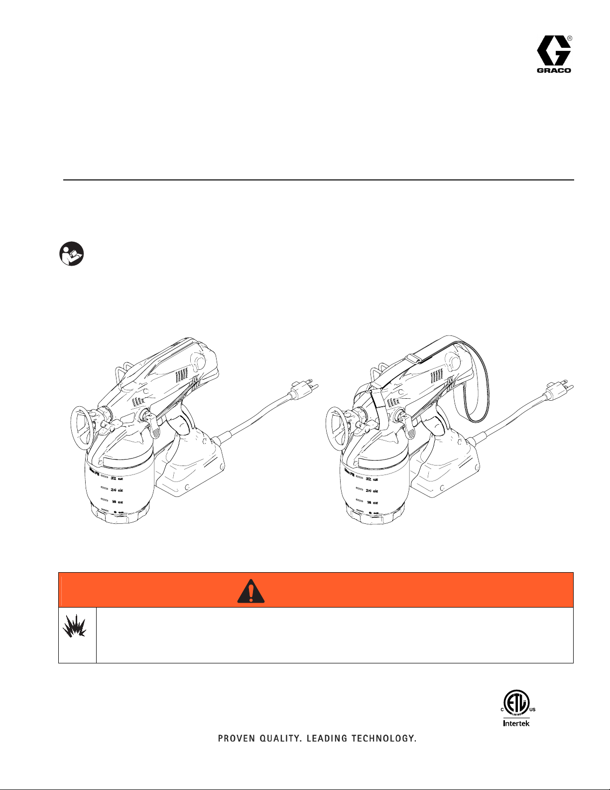
and TrueCoat™ Plus Paint Sprayers
- For portable spray applications of water-based and oil-based (mineral spirit-type)
architectural paints and coatings only-
IMPORTANT SAFETY INSTRUCTIONS
Read all warnings and instructions in this
manual. Save these instructions.
Models 258870, 258875, 258866, and 258863
Maximum Working Pressure 2000 psi (137 bar, 13.7 MPa)
www.graco.com
3A0159E
EN
TrueCoat Model: 258870 TrueCoat Plus Model: 258875
258866
WARNING
WARNINGWARNINGWARNING
Use only water-based or oil-based (mineral spirit-type) materials with flash point greater than 100° F
(38° C). Do not use materials which state “FLAMMABLE” on the packaging. For more information about
your material, request MSDS from distributor or retailer.
Use oil-based material outdoors or in a well-ventilated indoor area with a flow of fresh air.
258863
110474
Certified to CAN/CSA C22.2 No. 68
Conforms to
UL 1450
ti14773a
Page 2

Table of Contents
Table of Contents
Warnings . . . . . . . . . . . . . . . . . . . . . . . . . . . . . . . . . . . . . . 3
TrueCoa t™ Component Identification . . . . . . . . . . . . . . . 6
™
TrueCoa t
Using Electrical Cords . . . . . . . . . . . . . . . . . . . . . . . . . . . 8
Common Procedures . . . . . . . . . . . . . . . . . . . . . . . . . . . . 9
Setup . . . . . . . . . . . . . . . . . . . . . . . . . . . . . . . . . . . . . . . . 10
Plus Component Identification . . . . . . . . . . . 7
Grounding and Electrical Requirements . . . . . . . . . . . 8
Power Cord . . . . . . . . . . . . . . . . . . . . . . . . . . . . . . . . . . 8
Extension Cord Requirements . . . . . . . . . . . . . . . . . . . 8
Pressure Relief Procedure . . . . . . . . . . . . . . . . . . . . . . 9
Trigger Lock . . . . . . . . . . . . . . . . . . . . . . . . . . . . . . . . . 9
Spray Tip Position . . . . . . . . . . . . . . . . . . . . . . . . . . . . 9
Control Lever Position . . . . . . . . . . . . . . . . . . . . . . . . . 9
Overheating Protection . . . . . . . . . . . . . . . . . . . . . . . . 10
Installing Suction Tube . . . . . . . . . . . . . . . . . . . . . . . . 10
Spraying Stains or Clear Coats
(Fine-Finish Optimizer) . . . . . . . . . . . . . . . . . . . . 10
Sprayer Setup . . . . . . . . . . . . . . . . . . . . . . . . . . . . . . . 11
Important User Information
Read this before using your sprayer. See the Operation Manual provided with
your sprayer for complete instructions on proper use and safety warnings.
Install Tip/Guard Assembly
(if not installed) . . . . . . . . . . . . . . . . . . . . . . . . . . . . 13
Shoulder Strap Installation . . . . . . . . . . . . . . . . . . . . . 13
Basic Spraying Techniques . . . . . . . . . . . . . . . . . . . . . . 14
Triggering Sprayer . . . . . . . . . . . . . . . . . . . . . . . . . . . 14
Aiming Sprayer . . . . . . . . . . . . . . . . . . . . . . . . . . . . . . 14
Unclogging Spray Tip/Guard Assembly . . . . . . . . . . . . 15
Shutdown and Cleaning . . . . . . . . . . . . . . . . . . . . . . . . . 16
Flushing Sprayer . . . . . . . . . . . . . . . . . . . . . . . . . . . . 16
Cleaning Sprayer Exterior . . . . . . . . . . . . . . . . . . . . . 18
Tips . . . . . . . . . . . . . . . . . . . . . . . . . . . . . . . . . . . . . . 18
Storage . . . . . . . . . . . . . . . . . . . . . . . . . . . . . . . . . . . . . . . 18
Replacement Parts and Kits . . . . . . . . . . . . . . . . . . . . . . 19
Troubleshooting . . . . . . . . . . . . . . . . . . . . . . . . . . . . . . . 20
Alternate Priming Method . . . . . . . . . . . . . . . . . . . . . . . . 23
Inlet Valve Cleaning . . . . . . . . . . . . . . . . . . . . . . . . . . . . . 24
Technical Data . . . . . . . . . . . . . . . . . . . . . . . . . . . . . . . . . 25
Graco Standard Warranty . . . . . . . . . . . . . . . . . . . . . . . . 28
DO NOT RETURN THIS SPRAYER TO THE STORE!
If you experience problems call Graco Customer Service at 1-888-541-9788.
Congratulations! You have purchased a high-quality paint sprayer made by Graco Inc. This sprayer is designed to
provide superior spray performance with water-based and oil-based (mineral spirit-type) architectural paints and
coatings. This user information sheet is intended to help you understand the types of materials that can and cannot be
used with your sprayer.
Before using this equipment, be sure to read and follow the information on your container label and ask for a Material
Safety Data Sheet (MSDS). The container label and MSDS will explain the contents of the material and the specific
precautions related to it.
Paints, coatings and clean-up materials generally fit into one of the following 3 basic categories:
WATER-BASED: The container label should indicate that the material can be cleaned up with soap and
water. Your sprayer is compatible with this type of material. Your sprayer is NOT compatible with harsh
cleaners such as chlorine bleach.
OIL-BASED: The container label should indicate that the material is combustible and can be cleaned up with
mineral spirits or paint thinner. The MSDS must indicate that the flash point of the material is above 100° F.
Your sprayer is compatible with this type of material. Use oil-based material outdoors or in a well-ventilated
indoor area with a flow of fresh air. See the safety warnings in your Operation Manual.
FLAMMABLE: This type of material contains flammable solvents such as xylene, toluene, naphtha, MEK,
lacquer thinner, acetone, denatured alcohol, and turpentine. The container label should indicate that this
material is FLAMMABLE. This type of material is NOT compatible with your sprayer and CANNOT be used.
2 3A0159E
Page 3
Warnings
Warnings
The following warnings are for the setup, use, maintenance, and repair of this equipment. The exclamation point symbol alerts you to a general warning and the hazard symbols refer to procedure-specific risks. When these symbols
appear in the body of this manual, refer back to these Warnings. Product-specific hazard symbols and warnings not
covered in this section may appear throughout the body of this manual where applicable.
WARNING
WARNINGWARNINGWARNING
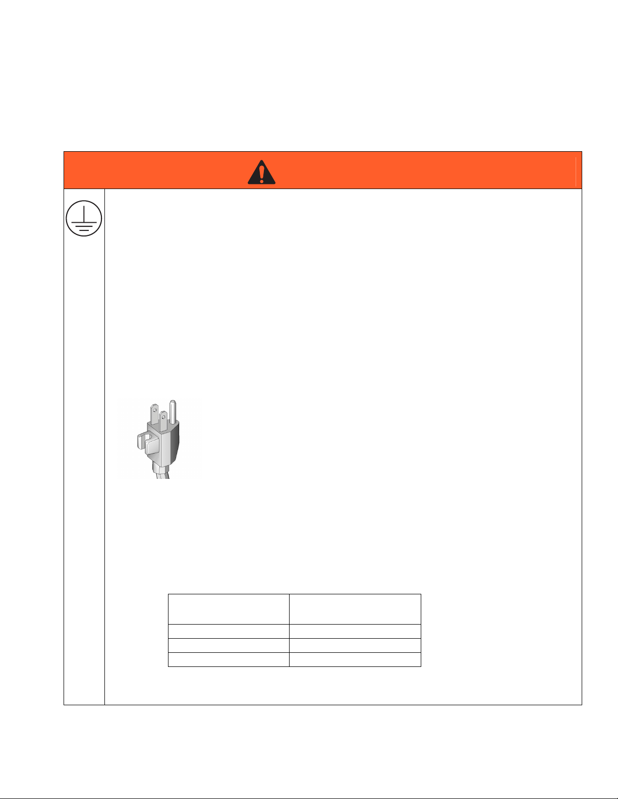
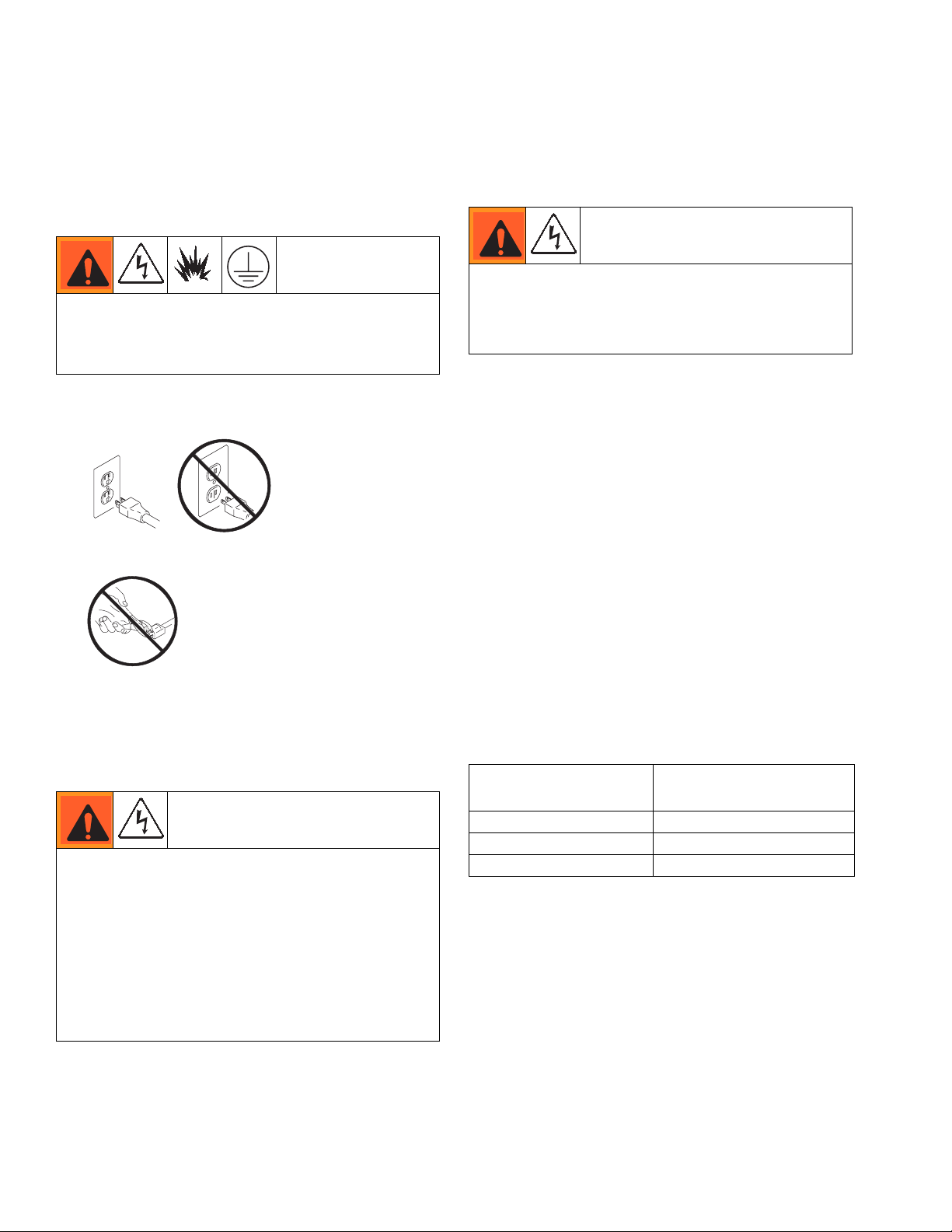
GROUNDING
This product must be grounded. In the event of an electrical short circuit, grounding reduces the risk of
electric shock by providing an escape wire for the electric current. This product is equipped with a cord
having a grounding wire with an appropriate grounding plug. The plug must be plugged into an outlet
that is properly installed and grounded in accordance with all local codes and ordinances.
• Improper installation of the grounding plug is able to result in a risk of electric shock.
• When repair or replacement of the cord or plug is required, do not connect the grounding wire to
either flat blade terminal.
• The wire with insulation having an outer surface that is green with or without yellow stripes is the
grounding wire.
• Check with a qualified electrician or serviceman when the grounding instructions are not completely
understood, or when in doubt as to whether the product is properly grounded.
• Do not modify the plug provided; if it does not fit the outlet, have the proper outlet installed by a
qualified electrician.
• This product is for use on a nominal 120V circuit and has a grounding plug similar to the plug
illustrated in the figure below.
• Only connect the product to an outlet having the same configuration as the plug.
• Do not use an adapter with this product.
Extension Cords:
• Use only a 3-wire extension cord that has a 3-blade grounding plug and a 3-slot receptacle that
accepts the plug on the product.
• Make sure your extension cord is not damaged. When using an extension cord, be sure to use a
cord heavy enough to carry the current that your sprayer draws. See chart for appropriate sizes and
lengths:
Extension Cord Gauge
(AWG Minimum)
18 50 ft (15 m)
16 100 ft (30 m)
14 200 ft (60m)
• An undersized extension cord will result in a drop in line voltage and loss of power, overheating, and
possible damage to equipment.
3A0159E 3
Extension Cord Length
(Maximum)
Page 4
Warnings
WARNING
WARNINGWARNINGWARNING
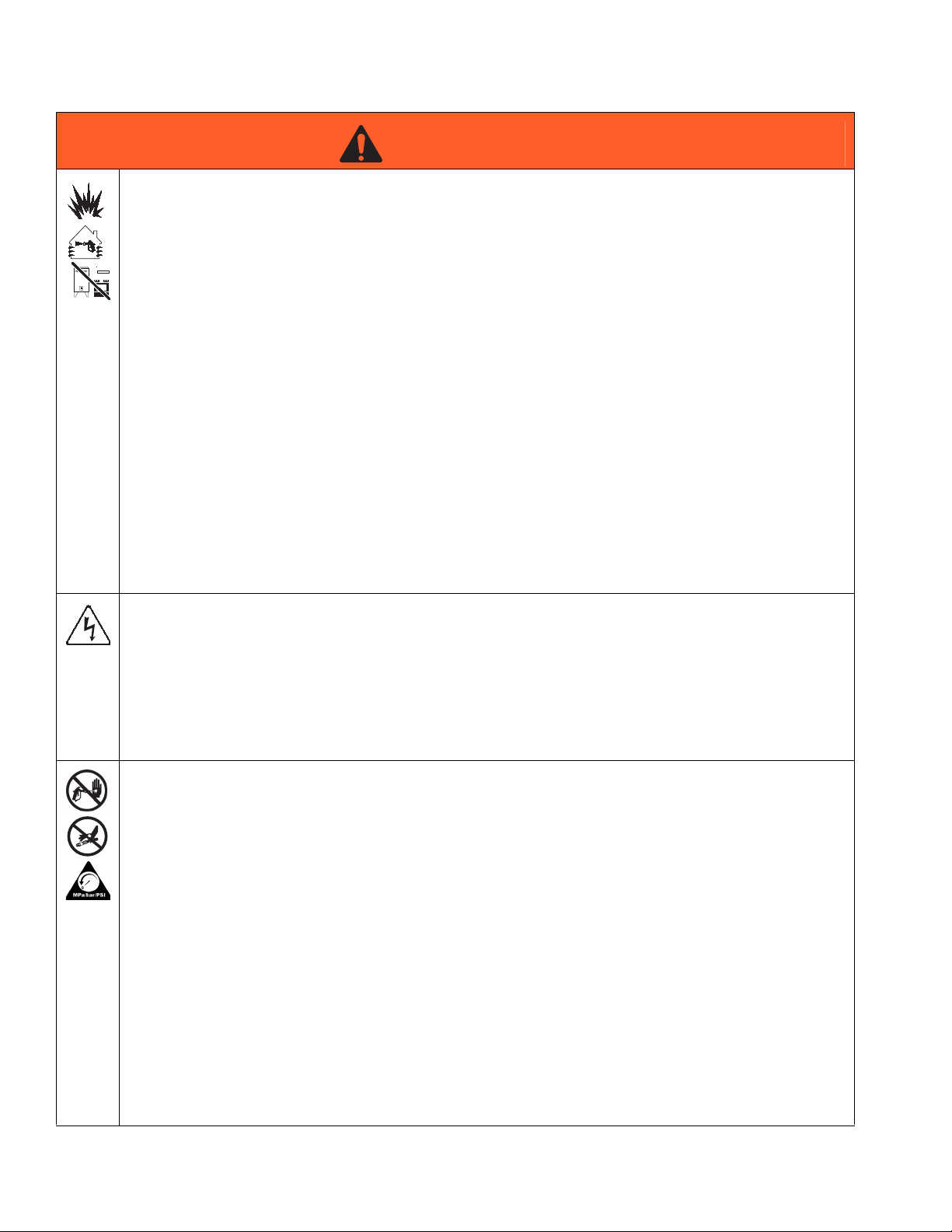
FIRE AND EXPLOSION HAZARD
Flammable fumes, such as solvent and paint fumes, in work area can ignite or explode. To help prevent
fire and explosion:
• Sprayer generates sparks. Do not spray or flush with flammable liquids.
• Use only water-based or oil-based (mineral spirit-type) materials with a flash point greater than
100° F (38° C).
• Keep spray area well-ventilated. Keep a good supply of fresh air moving through the area.
• Use oil-based material outdoors or in a well-ventilated indoor area with a flow of fresh air.
• Paint or solvent flowing through the equipment is able to result in static electricity. Static electricity
creates a risk of fire or explosion in the presence of paint or solvent fumes. All parts of the spray
system and objects in and around the spray area shall be properly grounded to protect against
static discharge and sparks.
• Verify that all containers and collection systems are grounded to prevent static discharge.
• Connect to a grounded outlet and use grounded extensions cords. Do not use a 3-to-2 adapter.
• Do not spray or flush with combustible materials near an open flame or sources of ignition.
• Do not smoke in the spray area.
• Do not operate light switches, engines, or similar spark producing products in the spray area.
• Keep area clean and free of paint or solvent containers, rags, and other flammable materials.
• Know the contents of the paints and solvents being sprayed. Read all Material Safety Data Sheets
(MSDS) and container labels provided with the paints and solvents. Follow the paint and solvents
manufacturer’s safety instructions.
• Fire extinguisher equipment shall be present and working.
ELECTRIC SHOCK HAZARD
This equipment must be grounded. Improper grounding, setup, or usage of the system can cause
electric shock.
• Turn off and disconnect power cord before servicing equipment.
• Use only grounded electrical outlets.
• Use only 3-wire extension cords.
• Ensure ground prongs are intact on power and extension cords.
• Do not expose to rain. Store indoors.
SKIN INJECTION HAZARD
High-pressure spray is able to inject toxins into the body and cause serious bodily injury. In the event that
injection occurs, get immediate surgical treatment.
• Do not aim the sprayer at, or spray any person or animal.
• Keep hands and other body parts away from the discharge. For example, do not try to stop leaks with
any part of the body.
• Always engage the trigger lock when not spraying. Verify the trigger lock is functioning properly.
• Always use the nozzle tip guard. Do not spray without nozzle tip guard in place.
• Use caution when cleaning and changing nozzle tips. In the case where the nozzle tip clogs while
spraying, follow the Pressure Relief Procedure for turning off the unit and relieving the pressure
before removing the nozzle tip to clean.
• Do not leave the unit energized or under pressure while unattended. When the unit is not in use, turn
off the unit and follow the Pressure Relief Procedure for turning off the unit.
• Check parts for signs of damage. Replace any damaged parts.
• This system is capable of producing 2000 psi. Use replacement parts or accessories that are rated a
minimum of 2000 psi.
• Do not carry the tool with a finger on the trigger.
• Verify that all connections are secure before operating the unit.
• Know how to stop the unit and bleed pressure quickly. Be thoroughly familiar with the controls.
4 3A0159E
Page 5
Warnings
WARNING
WARNINGWARNINGWARNING
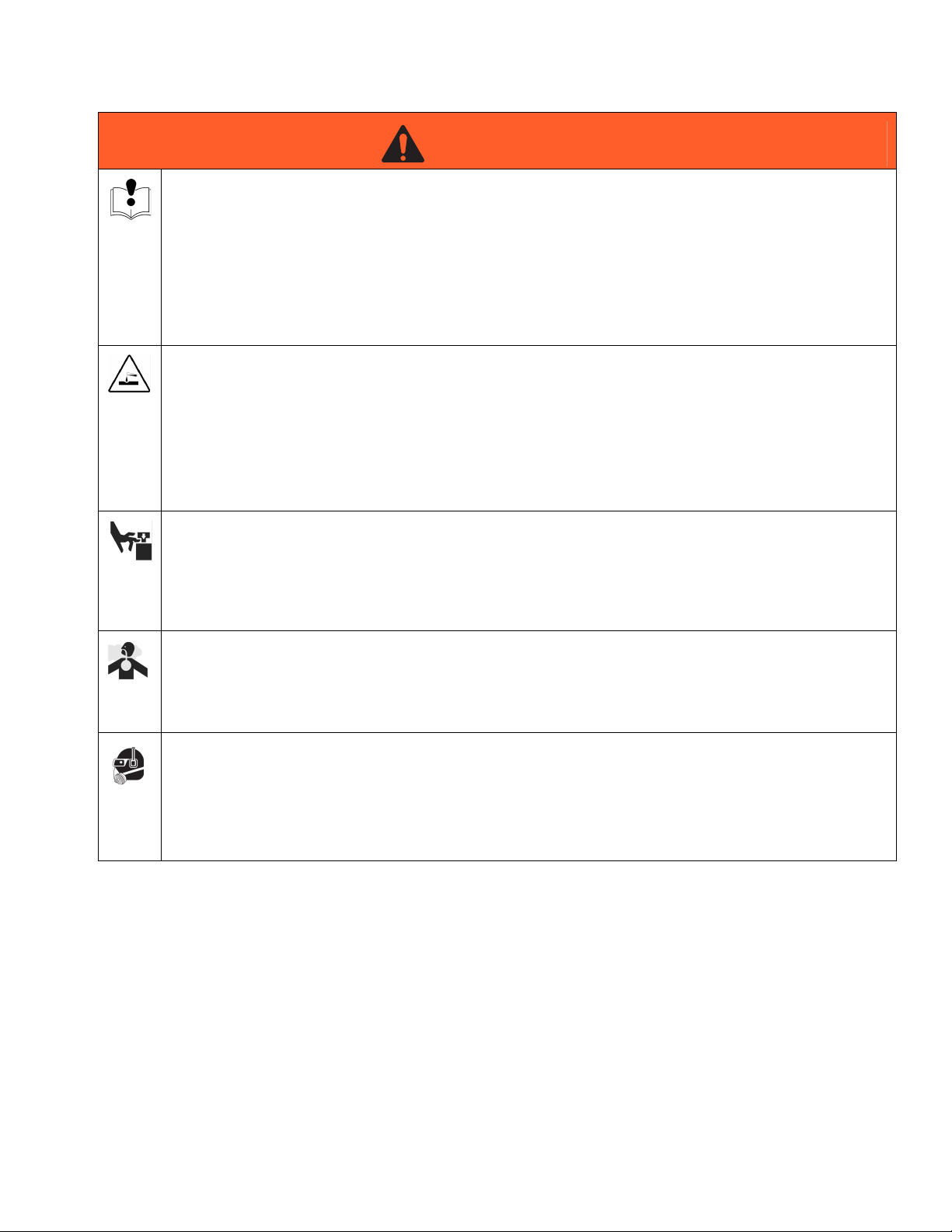
EQUIPMENT MISUSE HAZARD
Misuse can cause death or serious injury.
• Always wear appropriate gloves, eye protection, and a respirator or mask when painting.
• Do not operate or spray near children. Keep children away from equipment at all times.
• Do not overreach or stand on an unstable support. Keep effective footing and balance at all times.
• Stay alert and watch what you are doing.
• Do not operate the unit when fatigued or under the influence of drugs or alcohol.
• Use only in dry locations. Do not expose to water or rain.
• Use in well-lit areas.
PRESSURIZED ALUMINUM PARTS HAZARD
Use of fluids that are incompatible with aluminum in pressurized equipment can cause serious chemical
reaction and equipment rupture. Failure to follow this warning can result in death, serious injury, or
property damage.
• Do not use 1,1,1-trichloroethane, methylene chloride, other halogenated hydrocarbon solvents or
fluids containing such solvents.
• Many other fluids may contain chemicals that can react with aluminum. Contact your material
supplier for compatibility.
MOVING PARTS HAZARD
Moving parts can pinch or amputate fingers and other body parts.
• Keep clear of moving parts.
• Do not operate equipment with protective guards or covers removed.
• Pressurized equipment can start without warning. Before checking, moving, or servicing equipment,
follow the Pressure Relief Procedure in this manual. Disconnect power.
TOXIC FLUID OR FUMES HAZARD
Toxic fluids or fumes can cause serious injury or death if splashed in the eyes or on skin, inhaled, or swallowed.
• Read MSDS’s to know the specific hazards of the fluids you are using.
• Store hazardous fluid in approved containers, and dispose of it according to applicable guidelines.
PERSONAL PROTECTIVE EQUIPMENT
You must wear appropriate protective equipment when operating, servicing, or when in the operating
area of the equipment to help protect you from serious injury, including eye injury, hearing loss,
inhalation of toxic fumes, and burns. This equipment includes but is not limited to:
• Protective eyewear, and hearing protection.
• Respirators, protective clothing, and gloves as recommended by the fluid and solvent manufacturer.
3A0159E 5
Page 6
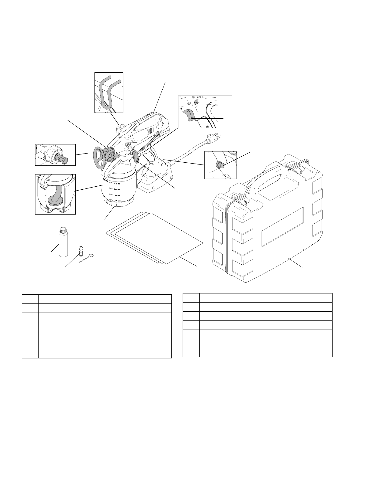
TrueCoat™ Component Identification
A
B
R
TrueCoat™ Component Identification
E
F
G
H
D
K
M
N
P
S
ti15479a
T
A TrueCoat Paint Sprayer
B Sprayer Hook
D TrueCoat Spray Tip/Guard Assembly (517 included)
E Tip Filter (*Reverse Threaded)
F Suction Tube
G Pump Armor Concentrate (4 oz.)
H Fine-Finish Optimizer with Storage/Cleaning Tool
*NOTE: Filter assembly is reverse-threaded. Turn left (or counter-clockwise) to tighten,
turn right (or clockwise) to loosen.
6 3A0159E
K Material Cup (32 oz)
M Control Lever
N Material Cup Liners (3 included)
P Sprayer Trigger
R Sprayer Trigger Lock
S Circuit Reset Button
T TrueCoat Case
Page 7
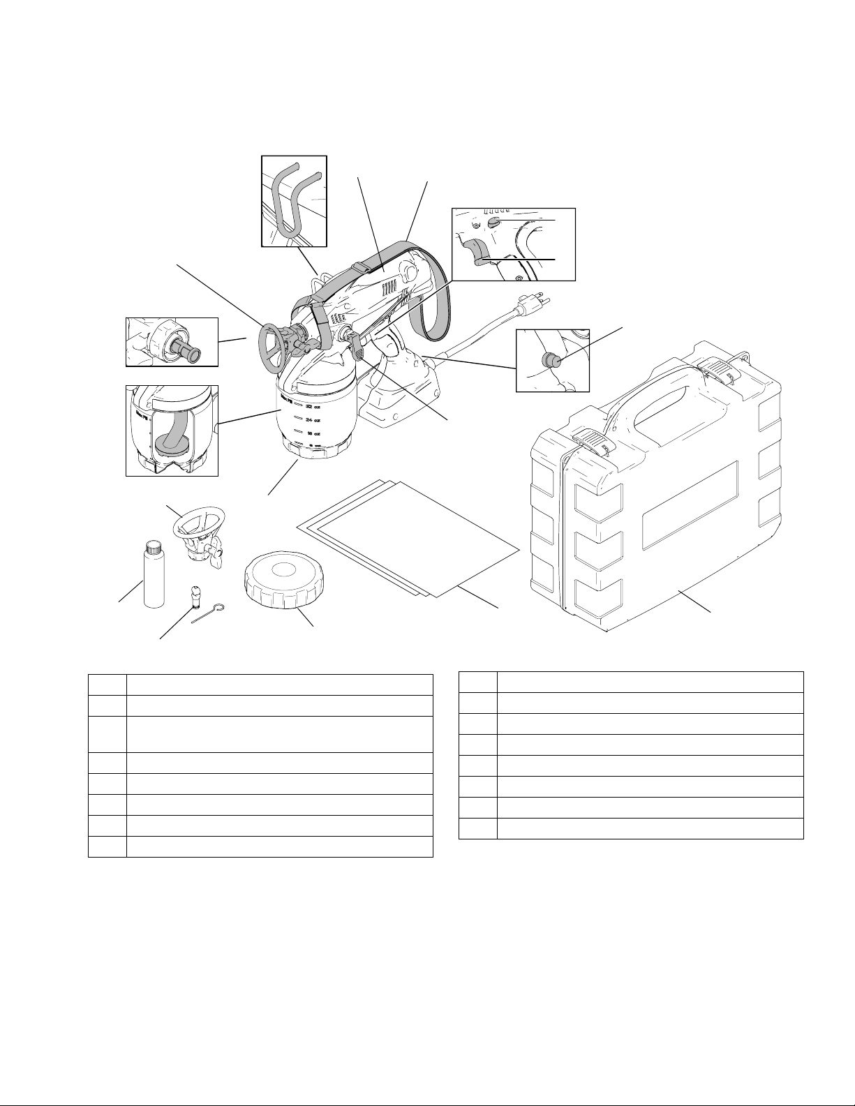
TrueCoat™ Plus Component Identification
TrueCoat™ Plus Component Identification
A
T
B
S
D
R
P
E
F
D
K
M
ti15479a
G
H
A TrueCoat Plus Paint Sprayer
B Sprayer Hook
TrueCoat Spray Tip/Guard Assembly
D
(311, 517 included)
E Tip Filter (*Reverse Threaded)
F Suction Tube
G Pump Armor Concentrate (4 oz.)
H Fine-Finish Optimizer with Storage/Cleaning Tool
J Material Cup Cover and Seal
*NOTE: Filter assembly is reverse-threaded. Turn left (or counter-clockwise) to tighten,
turn right (or clockwise) to loosen.
J
N
K Material Cup (32 oz)
M Control Lever
N Material Cup Liners (3 included)
P Circuit Reset Button
R Sprayer Trigger
S Sprayer Trigger Lock
T Shoulder Strap
W TrueCoat Case
W
3A0159E 7
Page 8
Using Electrical Cords
Using Electrical Cords
Grounding and Electrical Requirements
Sprayer must be grounded. Grounding reduces the risk
of static and electric shock by providing an escape wire
for electrical current due to static build up or in the
event of a short circuit.
This 120 Vac sprayer requires a 120 Vac, 60 Hz, 15A
circuit with a grounding receptacle.
Never use an outlet that is not grounded or an adapter.
Do not use the sprayer if the electrical cord has a damaged ground prong.
Extension Cord Requirements
Only use an extension cord with an undamaged
3-prong plug.
When operating sprayer outdoors, use an extension
cord suitable for outdoor use.
NOTE: When using an extension cord, always use a
cord coupler or an extension cord with locking plugs to
ensure that your sprayer maintains power during operation.
Your extension cord must have an adequate wire size
(AWG or American Wire Gauge) to be able to carry the
current that your sprayer draws. A smaller gauge number has a greater capacity than a large one. For example, 14 gauge wire has a greater capacity than 16 gauge
wire. An undersized extension cord will result in a drop
in line voltage and loss of power, overheating, and possible damage to equipment.
When using more than one extension cord, make sure
each individual cord contains at least the minimum wire
size needed. The table below shows the correct size to
use depending on extension cord size and gauge. If you
are unsure, it is better to use a heavier gauge than
needed. Remember, a smaller number indicates a larger
gauge wire.
Power Cord
Extension Cord Gauge
(AWG Minimum)
18 50 ft (15 m)
16 100 ft (30 m)
Damaged or entangled cords increase the risk of electric shock.
Do not abuse the sprayer cord.
Do NOT use the cord for carrying, pulling, or unplugging the sprayer.
Keep the cord away from heat, oil, sharp edges,
and moving parts.
Do not operate the sprayer with a damaged cord.
8 3A0159E
14 200 ft (60m)
Extension Cord Length
(Maximum)
Page 9
Common Procedures
Common Procedures
Pressure Relief Procedure
Do not operate or spray near children. Do not aim the
sprayer at, or spray any person or animal. Keep hands
and other body parts away from the front of the sprayer.
For example, do not try to stop the paint flow with any
part of the body.
This sprayer builds up an internal pressure of 2,000 psi
during use. Follow this Pressure Relief Procedure
whenever you stop spraying and before cleaning,
checking, servicing, or transporting equipment to
prevent serious injury.
1. Engage trigger lock.
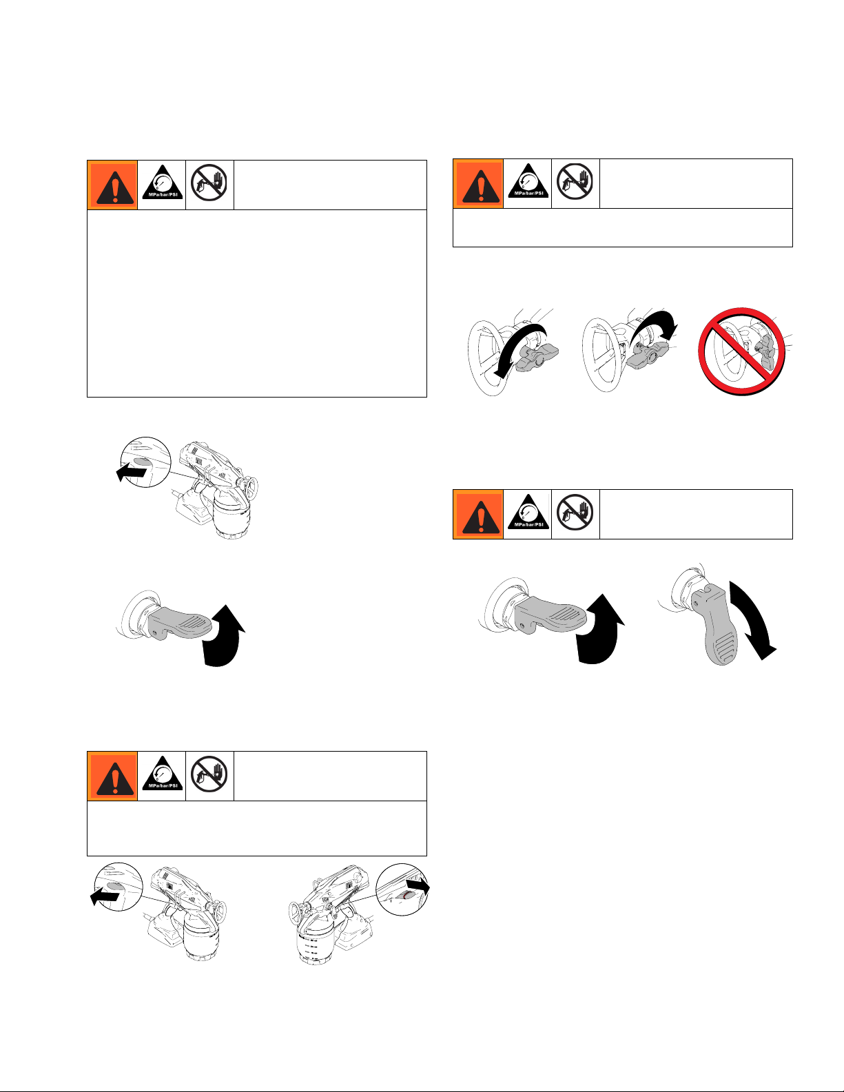
Spray Tip Position
Always perform Pressure Relief Procedure before
adjusting spray tip position.
This sprayer comes with reversible spray tips. Tips can
be rotated to two positions: SPRAY and UNCLOG.
ti14985a
Tip Forward
(SPRAY position)
ti14991a
Tip Reversed
(UNCLOG position)
ti15510a
Control Lever Position
2. Put control lever UP to release pressure.
ti14999a
Tri gger L ock
Always engage the trigger lock when you stop spraying
to prevent the sprayer from being triggered accidentally
by hand, or if dropped or bumped.
ti14994a
ti14995a
ti14999a
UP position
(Releases pump pressure)
ti15425a
DOWN position
(Ready to spray)
Trigger Locked
Trigger Unlocked
(red ring is visible)
3A0159E 9
Page 10

Setup
Setup
Spraying Stains or Clear Coats (Fine-Finish Optimizer)
Use only water-based or oil-based (mineral
spirit-type) materials with flash point greater than
100° F (38° C). Do not use materials which state
“FLAMMABLE” on the packaging. For more information about your material, request MSDS from distributor or retailer.
Use oil-based material outdoors or in a well-ventilated
indoor area with a flow of fresh air.
Keep spray area well-ventilated. Keep a good supply
of fresh air moving through the area.
NOTICE
Your sprayer is NOT compatible with harsh cleaners
such as chlorine bleach. Using these cleaners will
cause damage to the sprayer.
Overheating Protection
This sprayer has a built-in protective device to prevent
damage from overheating. The sprayer may automatically shut down after heavy use. If this happens, allow
the sprayer to cool down for 20-30 minutes and resume
spraying.
The Fine-Finish Optimizer must be installed and used
when spraying thin material (similar to water) such as
stain or clear coats. The Fine-Finish Optimizer restricts
the material flow resulting in a finer quality finish.
NOTICE
Failure to install the Fine-Finish Optimizer when using
the NAR311 tip or when spraying thin materials will
cause the motor to overheat and shutdown until it cools.
Installation
1. Remove material cup and suction tube.
2. Remove the cleaning tool before installing the
Fine-finish Optimizer into the sprayer.
Installing Suction Tube
Aim the inlet of the suction tube at the front of the material cup (towards Spray Tip/Guard Assembly) during
installation.
3. Push Fine-Finish Optimizer into pump inlet until
completely engaged and re-install suction tube.
Cleanup/Storage
Be sure to remove and clean the Fine-Finish Optimizer
immediately after use. Store the Fine-Finish Optimizer
on the Storage/cleaning Tool supplied to keep the hole
clear of dried material.
10 3A0159E
Page 11

Setup
Sprayer Setup
This sprayer arrives from the factory with a small
amount of test material in the system. It is important
that you flush this material or any storage fluid from
the sprayer before using it.
1. Plug sprayer into a properly-grounded outlet.
2. Fill material cup with water and thread onto sprayer.
ti14992a
3. Put control lever to UP position, then hold trigger in
for 10 seconds.
6. Engage trigger lock and put control lever UP to
release pressure.
ti14994a
ti14999a
7. Unscrew and remove material cup.
8. Disengage trigger lock, put control lever DOWN,
hold sprayer slightly above material cup, and pull
trigger to discharge fluid from pump.
ti14999a
4. Put control lever DOWN to spray position.
ti15425a
5. Reverse spray tip to UNCLOG position and trigger
sprayer into a waste area.
ti14991a
ti15491a
ti15478a
9. Discard material in the cup.
3A0159E 11
Page 12

Materials
Setup
3. Install material cup liner, fill with material, and
thread onto sprayer.
Use only water-based or oil-based (mineral
spirit-type) materials with flash point greater than
100° F (38° C). Do not use materials which state
“FLAMMABLE” on the packaging. For more information about your material, request MSDS from distributor or retailer.
Use oil-based material outdoors or in a well-ventilated
indoor area with a flow of fresh air.
Keep spray area well-ventilated. Keep a good supply
of fresh air moving through the area.
• When spraying water-based materials, flush the
sprayer thoroughly with water.
• When spraying non-water-based materials, flush
the sprayer thoroughly with mineral spirits or compatible, oil-based flushing fluid.
Starting a New Job (or Refilling the Cup)
1. Engage trigger lock and put control lever UP to
release pressure.
ti15474a
4. To begin using, disengage trigger lock and trigger
sprayer for 5-10 seconds. Then release trigger and
put control lever DOWN to spray position.
ti14995a
ti15418a
ti15425a
5. Reverse spray tip to UNCLOG position and spray
into waste area for 5 seconds. Then rotate tip back
to SPRAY position. NOTE: Failure to perform this
operation could result in poor spray pattern.
ti14994a
ti14999a
2. Use your Fine-Finish Optimizer cleaning tool to
lightly push on inlet valve to make sure it moves up
and down freely.
ti14991a
ti15491a
ti14985a
You are now ready to spray! If sprayer fails to
prime, follow the Alternative Priming Method
(page 23) and/or Inlet Valve Cleaning (page 24).
NOTE: If the sprayer is angled or tilted too far, the
suction tube will lose contact with the material and
the sprayer will stop spraying.
ti15511a
12 3A0159E
Page 13
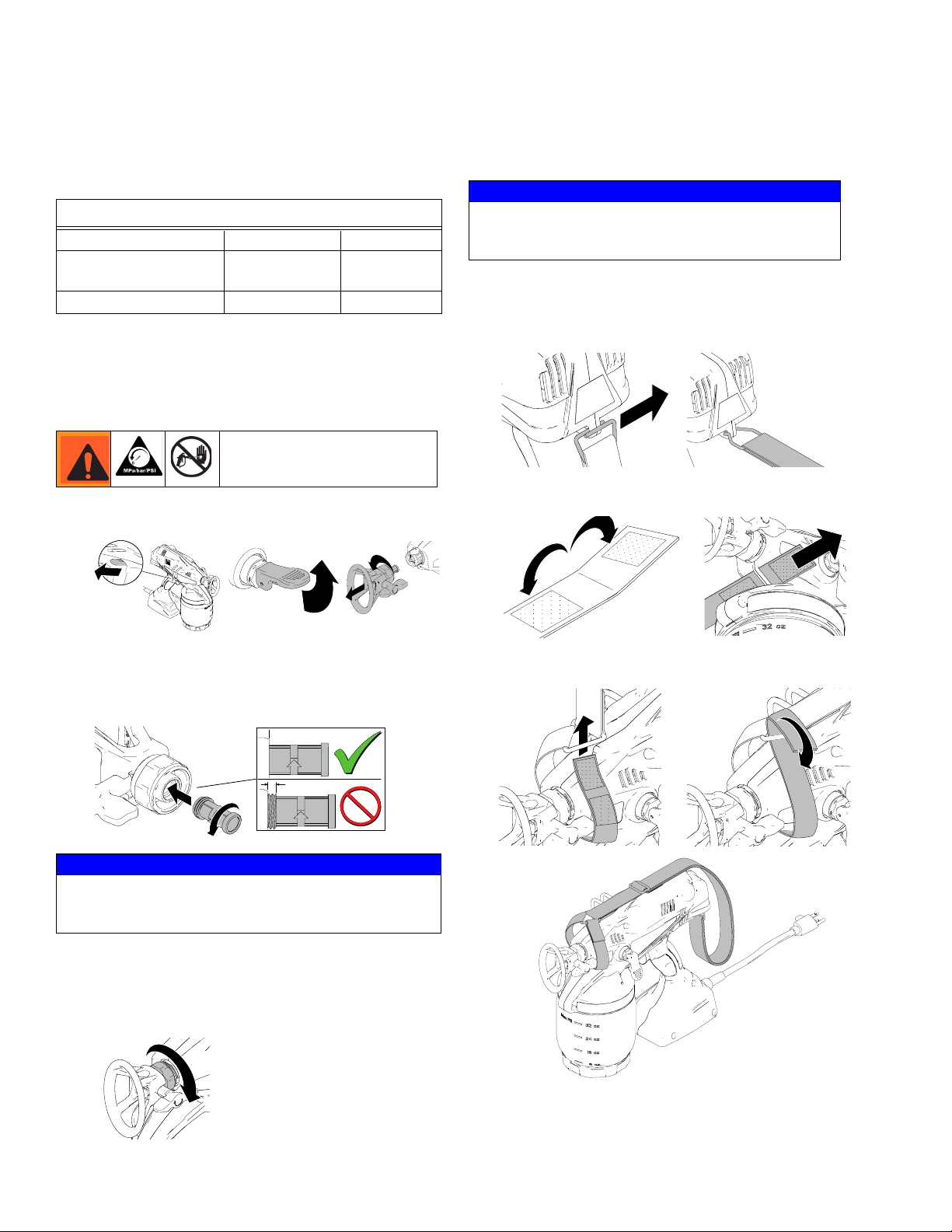
Install Tip/Guard Assembly (if not installed)
Install Tip/Guard Assembly
(if not installed)
Reversible Tip Selection Chart
MATERIALS
*Thin Medium Heavy
Thin stains,
semi-transparent stains
311 315, 515 517
*For thin materials install Fine-Finish Optimizer, page 10.
NOTE: Spraying thicker materials with a 311 tip may cause the
motor to overheat. Use the Reversible Tip Chart to determine
the correct tip for your application. If motor does overheat, allow
sprayer to cool for 20-30 minutes before operating.
1. Engage trigger lock and put control lever UP to release
pressure in the sprayer.
Enamels, solid
stains, thin latex
ti14999a
Heavy latex
NOTICE
The tip is a permanently attached to the guard.
Removing the tip from the guard will result in damage
to tip assembly.
Shoulder Strap Installation
1. Attach the metal eyelet to the back of the sprayer.
2. Open the velcro end of the strap, then route it through
the slot under the tip of the sprayer.
2. Install filter to Spray Tip/Guard Assembly. Make sure
filter is fully installed into sprayer. NOTE: Filter assembly is reverse-threaded. Turn left (or counter-clockwise) to install. Turn right (or clockwise) to remove.
ti14775a
NOTICE
Make sure filter is completely screwed into the Tip/Guard
Assembly to avoid splattering material or damage to the
filter.
3. Firmly screw Tip/Guard Assembly onto sprayer.
Tighten retaining nut until completely engaged with
sprayer. If Tip/Guard Assembly is not fully tightened,
poor spray results and possible damage to the sprayer
could occur.
ti14997a
3. Route velcro up through the metal triangle, then fold
down and attach velcro to strap.
3A0159E 13
Page 14

Basic Spraying Techniques
Basic Spraying Techniques
NOTE: Use a piece of scrap cardboard to practice these
basic spraying techniques before you begin spraying the
surface. Anything you don’t want painted that is in
the area of your spraying surface should be covered
or removed.
Hold sprayer at least 10 in. (25 cm) from surface and
adjust accordingly to achieve desired results. Aim
sprayer straight at surface. Tilting sprayer to direct spray
angle causes an uneven finish.
(25 cm)
10 in.
even
finish
thick
thin
uneven
finish
ti14780a
Flex your wrist while moving your arm to keep the
sprayer pointed straight. Tilting the sprayer or spraying
at an angle causes an uneven finish.
Even Finish Thin Thick Thin
Triggering Sprayer
To achieve even spraying, pull trigger after starting the
stroke. Release trigger before the end of the stroke.
Sprayer must be moving when trigger is pulled and
released.
ti14988a
Start Moving Pull Trigger Release Trigger
Aiming Sprayer
Aim tip of sprayer at bottom edge of previous stroke,
overlapping each stroke by half.
ti14986a
ti14987a
NOTE: How fast you move the sprayer will affect spray
application. If material is pulsating, you are moving too
fast. If material drips, you are moving too slow. See
Troubleshooting, page 20.
ti14782a
14 3A0159E
Page 15

Unclogging Spray Tip/Guard Assembly
Unclogging Spray
Tip/Guard Assembly
Do not operate or spray near children. Do not aim the
sprayer at, or spray any person or animal. Keep hands
and other body parts away from the discharge. For
example, do not try to stop leaks with any part of the
body.
Occasionally, debris from material can accumulate and
clog the spray tip. Perform the following steps to unclog
the tip.
1. To unclog tip obstruction, engage trigger lock and
pull control lever UP to release pressure.
4. Engage trigger lock. Put control lever UP to release
pressure and rotate spray tip back to SPRAY position.
ti14994a
ti14999a
ti14985a
5. Disengage trigger lock, put control lever DOWN to
spray position, and resume spraying.
ti14995a
ti15425a
6. If tip is still clogged, you may have to repeat steps
1 - 5 and rotate the tip from SPRAY to UNCLOG
several times. Repeat step 1 to release pressure,
remove and clean filter, or replace with new tip
assembly.
ti14994a
ti14999a
2. Reverse spray tip to UNCLOG position.
ti14991a
3. Aim sprayer at waste area, disengage trigger lock,
and put control lever DOWN to spray position. Pull
trigger to clear clog.
ti14995a
ti15425a
ti14989a
NOTE: Filter assembly is reverse-threaded:
Turn l eft (or counter-clockwise) to install.
Turn r igh t (or clockwise) to remove.
7. If obstruction is cleared, engage trigger lock and
rotate arrow-shaped handle back to SPRAY
position.
3A0159E 15
Page 16

Shutdown and Cleaning
Shutdown and Cleaning
NOTICE
Failure to properly clean sprayer after each use will result
in hardened materials, damage to the sprayer, and the
warranty will no longer be valid.
Flushing Sprayer
Use only water-based or oil-based (mineral
spirit-type) materials with flash point greater than
100° F (38° C). Do not use materials which state
“FLAMMABLE” on the packaging. For more
information about your material, request MSDS
from distributor or retailer.
Use oil-based material outdoors or in a well-ventilated
indoor area with a flow of fresh air.
Keep spray area well-ventilated. Keep a good supply
of fresh air moving through the area.
3. Remove and clean sprayer intake tube and screen
with water (or flushing fluid) and a brush every time
you flush the sprayer. Reconnect intake tube.
ti15002a
4. Clean cup if not using a liner, and fill with water or
appropriate flushing fluid.
ti15001a
NOTICE
Protect the internal parts of this sprayer from water.
Do not submerge the sprayer in cleaning fluid. Openings
in shroud allow cooling of mechanical parts and electronics inside. If water gets into these openings, the sprayer
could malfunction or become permanently damaged.
1. Engage trigger lock and pull control lever UP to
release pressure.
ti14994a
ti14999a
2. Remove material cup and properly dispose cup liner
or excess material.
5. Reconnect material cup and shake sprayer to move
clean water around and clean all areas inside of
cup and underside of sprayer.
ti15441a
6. Disengage trigger lock and trigger sprayer for
approximately 15 seconds. Engage trigger lock.
ti14994a
16 3A0159E
Page 17

Shutdown and Cleaning
7. Discard contaminated fluid and refill with appropriate flushing fluid.
8. Disengage trigger lock, reverse tip to UNCLOG
position, and pull trigger for 5 seconds to prepare
sprayer.
ti14995a
9. Put control lever DOWN to spray position.
Trigger sprayer into waste area until no paint
appears in water or flushing fluid.
ti15425a
ti15491a
To avoid serious injury or damage to equipment, do not
expose the sprayer electronics to flushing solvents.
Keep sprayer at least 10 in. above the rim of the container when flushing.
11. Remove material cup and discard used fluid.
12. Use a soft brush to clean the black rubber inlet seal.
If the vent holes become clogged, use the Fine Finish Optimizer cleaning tool or a paper clip to clear
the holes.
13. Remove Spray Tip/Guard Assembly and clean with
water or flushing fluid. A soft brush can be used to
loosen and remove dried material if needed. Run
underwater and use a soft brush to clean the filter.
ti15003a
ti15529a
NOTICE
Keep spray area well-ventilated. Keep a good supply
of fresh air moving through the area.
10. Engage trigger lock and put control lever UP to
release pressure.
The tip is a permanently attached to the guard.
Removing the tip from the guard will result in damage
to tip assembly.
14. Replace tip assembly.
15. If you used the Fine-Finish Optimizer, remove and
clean optimizer with water (or flushing fluid) and a
brush. Reconnect intake tube.
ti14994a
3A0159E 17
ti14999a
Page 18

Storage
Cleaning Sprayer Exterior
• Wipe paint off outside of sprayer using a soft cloth
moistened with water or flushing fluid.
Do NOT submerge the sprayer.
Tips
• Tips will require replacement depending on
abrasiveness of paint.
• Do not spray with worn tip. See Troubleshooting,
page 20.
Storage
2. Thread cup into sprayer, put control lever to UP
position and squeeze sprayer trigger for approximately 10 seconds.
ti14999a
3. Reverse spray tip to UNCLOG position, put control
lever DOWN to spray position, and aim sprayer into
waste area. Pull trigger for 1-2 seconds.
ti15425a
4. Properly dispose of used Pump Armor mixture from
material cup and rinse cup with water.
NOTICE
Failure to store with sprayer with Pump Armor will
result in operational problems the next time you spray.
Always circulate Pump Armor through the sprayer
after cleaning. Water left in the sprayer will corrode
and damage the pump.
1. Dilute 4 oz. bottle of Pump Armor Concentrate with
an additional 4 oz. of water in material cup.
4 oz
ti15442a
ti15001a
5. Store sprayer indoors in a cool, dry place. Store
storage case in an upright position only.
ti15438a
18 3A0159E
Page 19

Replacement Parts and Kits
Replacement Parts and Kits
1
2
16
14
17
15
11
10
11a
12
7
5
3
4
8
9
11
11a
13
6
ti15497a
Ref. Part Description
1 24E377 Shoulder Strap
2 24F045 Fine Finish Optimizer (with Cleaning Tool)
2-Pack
3 TrueCoat Tip/Guard Assembly
NAR311 311
NAR315 315
XWD515 515
XWD517 517
4 24F078 Storage Case
5 Tip Filter
24E376 Kit, 1-pack
24F039 Kit, 3-pack
6▲ 24E609 Warning Labels, replacement kit
7 24F076 Suction Tube with screens and o-rings
8 16E403 Sprayer Cup Seal
9 16D562 Liner, replacement (10 pack)
3A0159E 19
Ref. Part Description
10 243103 Pump Armor (32 oz.)
11 24D425 Cover with seal (included in 12 and 13)
11a 16C650 Material Cup Cover Seal
(included 12 and 13)
12 24E375 Material Cup (48 oz) cover and seal
13 24E374 Material Cup (32 oz) cover and seal
106553 Suction Tube o-ring (not shown)
14 262460 SPRAYER, replacement, TrueCoat
262459 SPRAYER, replacement, TrueCoat Plus
15 262602 Inlet Valve Kit
16 262438 Needle Assembly Kit
17 262601 Prime Valve Handle
▲ Replacement Danger and Warning labels, tags, and
cards are available at no cost.
Page 20

Troubleshooting
Problem Cause Solution
Troubleshooting
Check everything in this Troubleshooting Table before
you bring the sprayer to an authorized service center.
Sprayer makes no sound when
trigger is pulled
Sprayer makes sound but no material is
sprayed when trigger is pulled
Trigger is locked. Disengage trigger lock. See page 9.
Sprayer is not receiving power. Plug in sprayer or check outlet for power.
Sprayer motor is overheated. Wait 20-30 minutes for motor to cool.
Sprayer circuit breaker has tripped. Push and hold circuit reset button (see
pages 6 and 7).
Sprayer has not been Setup. Setup the sprayer. See Starting a new
Job (or Refilling the Cup), page 12. If
sprayer fails to prime, follow the Alterna-
tive Priming Method (page 23) and/or
Inlet Valve Cleaning (page 24).
Control lever is in UP position. Pull control lever DOWN to spray posi-
tion.
Suction Tube is missing or improperly
installed.
Inlet valve is stuck from material
residue left in sprayer.
Tip is not in SPRAY position. Turn tip to SPRAY position.
Tip is clogged. See Unclogging Tip/Guard
Suction Tube screen is clogged or vent
holes in black rubber inlet seal are
clogged.
Sprayer has been tilted too far and suction tube has lost contact with material.
No or low material in cup. Refill cup with material.
Tip filter is clogged. Remove and clean tip filter. See Unclog-
Fine Finish Optimizer is installed while
using an incompatible material.
Suction Tube o-rings are damaged or
missing.
Pump is clogged, frozen, or has debris
inside.
Sprayer has reached maximum life. Replace sprayer.
Material is leaking from hole in front of
sprayer.
Make sure Suction Tube is properly
installed.
Use a pencil or thin rod to lightly push on
inlet valve to make sure it moves up and
down freely, see page 12. Inlet valve may
need to be removed and cleaned.
See Inlet Valve Cleaning, page 24.
Assembly, page 15.
See Shutdown and Cleaning, page 16.
Make sure cup is filled with material. Do
not tilt the cup too far. Setup the sprayer.
See Starting a new Job (or Refilling the
Cup), page 12.
ging Tip/Guard Assembly, page 15.
Make sure compatible material is being
used. See Reversible Tip Selection
Chart, page 13.
Replace Suction Tube and o-rings.
Flush the pump. See Setup, page 10.
Replace sprayer.
20 3A0159E
Page 21

Troubleshooting
Problem Cause Solution
Sprayer sprays with poor results Tip is partially clogged See Unclogging Tip/Guard
Assembly, page 15.
Tip is not in correct position Rotate tip to SPRAY position.
Incorrect tip for application of
material.
Tip filter is partially clogged Clean or replace filter. See page 15.
Suction Tube screen is partially
clogged.
Fine Finish Optimizer is partially
clogged.
Fine Finish Optimizer is installed
while using an incompatible material.
Tip is worn or damaged Replace tip. See Install Tip/Guard
Inlet or Outlet Valves are worn. Replace sprayer.
Sprayer is pulsating while spraying
water.
Paint leaks from sprayer trigger area. Sprayer has reached its maximum
life.
See Reversible Tip Selection
Chart, page 13.
Clean or replace Suction Tube. See
page 16.
Clean or replace Fine Finish Optimizer. See page 10.
Make sure compatible material is
being used. See Reversible Tip
Selection Chart, page 13.
Assembly, page 13.
Fine-Finish Optimizer is not installed.
See page 10.
Replace sprayer.
Spray Pattern Diagnostics
Problem Cause Solution
Spray pattern is pulsating: The Fine-Finish Optimizer is installed
while using thick material.
Operator is moving too fast while
spraying.
ti15524a
Spray pattern has tails: Fine Finish Optimizer is installed while
using an incompatible material.
Fine Finish Optimizer is partially
clogged.
ti15526a
Material not compatible with sprayer.
Inlet or Outlet Valves are worn.
Make sure material and tip are compatible. See Reversible Tip Selection Chart,
page 13.
Slow speed of movement.
Make sure compatible material is being
used. See Reversible Tip Selection
Chart, page 13.
Clean or replace Fine Finish Optimizer.
See page 10.
Switch material.
Replace sprayer.
3A0159E 21
Page 22

Problem Cause Solution
Troubleshooting
Spray pattern has dripping: Sprayer is moving too slow for material.
Sprayer is too close to target surface.
Holding trigger while changing spray
direction.
ti15522a
Incorrect tip for application of
material.
Tip is worn or damaged.
Spray pattern is too narrow: Sprayer is too close to target surface.
Incorrect tip for application of material.
ti15523a
Tip is worn or damaged.
Spray pattern is too wide: Sprayer is too far away from target sur-
face.
Incorrect tip for application of material.
Move sprayer faster while spraying.
Move sprayer away from surface (10 in).
Release trigger when changing directions.
See Reversible Tip Selection Chart,
page 13.
Replace tip. See Install Tip/Guard
Assembly, page 13.
Move sprayer away from surface (10 in).
See Reversible Tip Selection Chart,
page 13.
Replace tip. See Install Tip/Guard
Assembly, page 13.
Move sprayer closer to surface.
See Reversible Tip Selection Chart,
page 13.
Spray pattern “spits” at the
end:
ti15525a
Tip continues to drip or ooze
material after trigger is
released:
ti15528a
Spray pattern does not
adequately cover target
surface
Excess material has accumulated on
Spray Tip/Guard Assembly.
Tip filter is partially clogged.
Tip/Guard Assembly not threaded completely onto sprayer.
Seat is worn.
Sprayer is worn out.
Tip/Guard Assembly not threaded completely onto sprayer.
Fine Finish Optimizer is installed while
using an incompatible material.
See Shutdown and Cleaning, page 16.
Clean or replace filter. See page 15.
See Install Tip/Guard Assembly, page
13.
Replace Spray tip.
Replace sprayer.
See Install Tip/Guard Assembly, page
13.
Make sure compatible material is being
used. See Reversible Tip Selection
Chart, page 13.
Sprayer is worn out.
22 3A0159E
Replace sprayer.
Page 23

Alternate Priming Method
Alternate Priming Method
1. Engage trigger lock and put prime/relief valve UP to
release pressure.
ti14994a
2. Remove material cup and fill with flushing material.
ti14999a
4. Hold sprayer above sink or waste area, disengage
the trigger lock, and quickly trigger sprayer until
material comes out of the drain tube.
ti14995a
ti14991a
NOTE: Material can shoot out of the drain tube
when performing this procedure. Be sure to wear
appropriate safety equipment and point drain tube
away from yourself when pulling the trigger,
5. Thread the material cup back onto sprayer.
3. With sprayer in prime mode, turn sprayer
upside-down, remove strainer and slowly pour
flushing material into the intake tube until full.
6. Trigger the gun for 10 seconds then release the
trigger and put the prime/relief valve DOWN to spray
position.
ti15425a
7. Reverse spray tip to UNCLOG position and spray
into waste area for five seconds to ensure sprayer
has primed.
ti14995a
8. Sprayer is now ready to spray. Follow Starting New
Job instructions on page 12.
3A0159E 23
Page 24

Inlet Valve Cleaning
Inlet Valve Cleaning
Removal
1. Engage trigger lock and pull relief valve UP to
release pressure.
ti14994a
2. Remove material cup and suction tube.
ti15504a
3. Hold sprayer upside-down and use wrench or
socket to loosen and remove inlet fitting, inlet valve,
and spring.
ti14999a
4. Clean as much excess material from pump cavity as
possible. Make sure you also clean spring (a), o-ring
(c), and top of inlet fitting (d).
Installation
NOTE: Before installing, make sure o-ring (c) is installed
on inlet valve (b).
1. Place inlet valve (b) with spring (a) on top of inlet fitting (d). Push inlet fitting up into pump cavity.
a
b
c
d
ti15502a
2. Hold inlet in place and turn sprayer upside-down.
Remove inlet fitting and visually check to see that
inlet valve has seated correctly.
3. Replace inlet fitting and use wrench and socket to
tighten to 10 ft-lb.
NOTICE
Do NOT over-tighten inlet fitting. Damage to the
ti15505a
NOTE: Make sure the spring also comes out. Use
needle-nose pliers to remove if needed. Inlet cavity
should be completely empty (as shown below).
ti15530a
24 3A0159E
equipment will occur.
4. Use your Fine-Finish Optimizer cleaning tool to
lightly push on inlet valve to make sure it moves up
and down freely.
ti15509a
Page 25

Technical Data
Technical Data
Sprayer:
Maximum working pressure 2000 psi (137.8 bar, 13.7 MPa)
Maximum amperage 4 amps
Weight 5.89 lb (2.67 kg)
Dimensions:
Length 13.25 in. (33.6 cm)
Width 5.0 in. (12.7 cm)
Height 10.75 in. (27.3 cm)
Storage temperature range ◆❖ 32° to 122°F (0° to 50°C)
Operating temperature range ✔ 40° to 90° F (4° to 32°C)
Storage Humidity Range 0% to 95% relative humidity, non-condensing
Duty Cycle 50%
Power Cord 18 AWG, 3-wire, 18 in. (46 cm)
Electrical Power Requirement 120 Vac, 60 Hz, 15A, 1 phase
◆ Pump damage will occur if fluid freezes in pump.
❖ Damage to plastic parts may result if impact occurs in low temperature conditions.
✔ Changes in paint viscosity at very low or very high temperatures can affect sprayer performance.
3A0159E 25
Page 26

Notes
Technical Data
26 3A0159E
Page 27

Technical Data
Notes
3A0159E 27
Page 28

Graco Standard Warranty
Graco warrants all equipment referenced in this document which is manufactured by Graco and bearing its name to be free from defects in
material and workmanship on the date of sale to the original purchaser for use. With the exception of any special, extended, or limited warranty
published by Graco, Graco will, for a period of twelve months from the date of sale, repair or replace any part of the equipment determined by
Graco to be defective. This warranty applies only when the equipment is installed, operated and maintained in accordance with Graco’s written
recommendations.
This warranty does not cover, and Graco shall not be liable for general wear and tear, or any malfunction, damage or wear caused by faulty
installation, misapplication, abrasion, corrosion, inadequate or improper maintenance, negligence, accident, tampering, or substitution of
non-Graco component parts. Nor shall Graco be liable for malfunction, damage or wear caused by the incompatibility of Graco equipment with
structures, accessories, equipment or materials not supplied by Graco, or the improper design, manufacture, installation, operation or
maintenance of structures, accessories, equipment or materials not supplied by Graco.
This warranty is conditioned upon the prepaid return of the equipment claimed to be defective to an authorized Graco distributor for verification of
the claimed defect. If the claimed defect is verified, Graco will repair or replace free of charge any defective parts. The equipment will be returned
to the original purchaser transportation prepaid. If inspection of the equipment does not disclose any defect in material or workmanship, repairs will
be made at a reasonable charge, which charges may include the costs of parts, labor, and transportation.
THIS WARRANTY IS EXCLUSIVE, AND IS IN LIEU OF ANY OTHER WARRANTIES, EXPRESS OR IMPLIED, INCLUDING BUT NOT LIMITED
TO WARRANTY OF MERCHANTABILITY OR WARRANTY OF FITNESS FOR A PARTICULAR PURPOSE.
Graco’s sole obligation and buyer’s sole remedy for any breach of warranty shall be as set forth above. The buyer agrees that no other remedy
(including, but not limited to, incidental or consequential damages for lost profits, lost sales, injury to person or property, or any other incidental or
consequential loss) shall be available. Any action for breach of warranty must be brought within two (2) years of the date of sale.
GRACO MAKES NO WARRANTY, AND DISCLAIMS ALL IMPLIED WARRANTIES OF MERCHANTABILITY AND FITNESS FOR A
PARTICULAR PURPOSE, IN CONNECTION WITH ACCESSORIES, EQUIPMENT, MATERIALS OR COMPONENTS SOLD BUT NOT
MANUFACTURED BY GRACO. These items sold, but not manufactured by Graco (such as electric motors, switches, hose, etc.), are subject to
the warranty, if any, of their manufacturer. Graco will provide purchaser with reasonable assistance in making any claim for breach of these
warranties.
In no event will Graco be liable for indirect, incidental, special or consequential damages resulting from Graco supplying equipment hereunder, or
the furnishing, performance, or use of any products or other goods sold hereto, whether due to a breach of contract, breach of warranty, the
negligence of Graco, or otherwise.
FOR GRACO CANADA CUSTOMERS
The Parties acknowledge that they have required that the present document, as well as all documents, notices and legal proceedings entered into,
given or instituted pursuant hereto or relating directly or indirectly hereto, be drawn up in English. Les parties reconnaissent avoir convenu que la
rédaction du présente document sera en Anglais, ainsi que tous documents, avis et procédures judiciaires exécutés, donnés ou intentés, à la suite
de ou en rapport, directement ou indirectement, avec les procédures concernées.
Graco Information
For the latest information about Graco products, visit www.graco.com. Contact Graco Customer Service at 1-888-541-9788.
All written and visual data contained in this document reflects the latest product information available at the time of publication.
GRACO INC. AND SUBSIDIARIES • P.O. BOX 1441 • MINNEAPOLIS MN 55440-1441 • USA
Copyright 2011, Graco Inc. All Graco manufacturing locations are registered to ISO 9001.
Graco reserves the right to make changes at any time without notice.
Original instructions. This manual contains English. MM 3A0159
Graco Headquarters: Minneapolis
International Offices: Belgium, China, Japan, Korea
www.graco.com
Revised 11/2011
 Loading...