

Page 1
Kit Instructions
300 psi LPG Gauge for ThermoLazer
Model 24T885
Important Safety Instructions
Read instruction manual 3A1319 for complete instructions and warnings. This Kit is not
a substitute for reading and understanding all instruction manuals and warning labels
supplied with the equipment.
1
332653A
EN
6
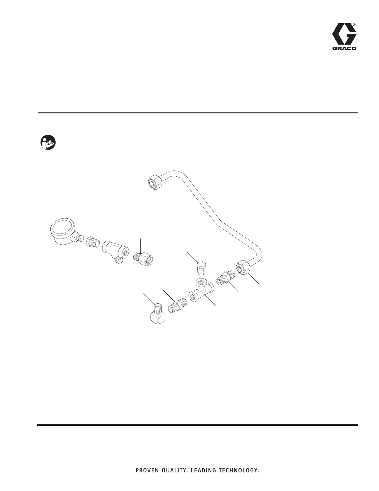
Ref. Part Description Qty.
1 127257 GAUGE, pressure, 0-300 psi 1
3 16W412 TUBE, formed, gas 1
4 118484 FITTING, connector 1
5 104984 FITTING, tee, pipe 1
6 100030 BUSHING 2
7 156971 FITTING, nipple, short 1
8 100840 FITTING, elbow, street 1
10 16W635 FITTING, system filter assembly 1
11 108638 FITTING, pipe, tee 1
12 070408 SEALANT, pipe, sst (not shown) 1
13 110110 SEALANT, pipe, sst (not shown) 1
14 555459 PLUG, 1/4 npt brass hex hd 1
11
10
8
14
7
3
4
5
Page 2
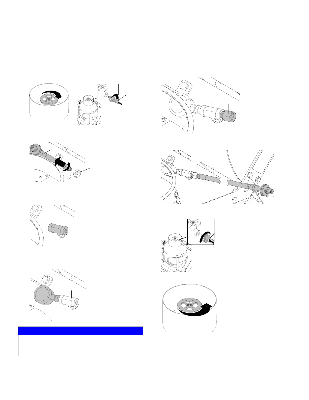
300 psi LPG Gas Gauge Installation for ThermoLazer
1. Close manual gas shutoff valve on propane tank,
then disconnect gas supply hose (99) from propane
tank.
99
ti14128a
ti22097a
2. Unscrew gas supply hose (99) from bulkhead fitting
(102).
99
102
ti22105a
3. Apply pipe sealant to tee fitting (11) and screw into
bulkhead fitting (102). Screw in until gas tight. Install
tee as shown.
11
5. Apply pipe sealant to filter fitting (10) and screw into
tee fitting (11). Screw in until gas tight.
11
10
ti22098a
6. Apply pipe sealant to hose (99) and screw into filter
fitting (10). Screw in until gas tight.
10
99
ti22099a
7. Connect gas supply hose (99) to propane tank.
ti22101a
4. Apply pipe sealant to bushing (6) and screw into tee
fitting (11). Screw in until gas tight. Position gauge
(1) as shown.
1
6
11
ti22100a
NOTICE
Tighten by turning bushing (6) and holding tee fitting
(11). Do NOT turn gauge (1). Damage to the gauge
will occur.
99
ti14411b
8. Open manual gas shutoff valve on propane.
ti14127a
9. Check gas line for gas leaks (see ThermoLazer
Operation Manual).
2 332653A
Page 3

Pressure Tap Installation for ThermoLazer
Pressure Tap Installation for ThermoLazer
1. Close manual gas shutoff valve on propane tank.
ti14128a
2. Disconnect gas supply hose (99) from propane tank.
99
ti22097a
3. Remove and discard existing gas line (3) by
unscrewing from elbow fitting (161) and unscrewing
from gas safety valve adapter fitting (164).
4. Remove and discard existing elbow fitting (161) by
unscrewing from manual gas shutoff valve (9).
9. Install new gas line (3) by screwing into gas safety
valve adapter fitting (164) and screwing into adapter
fitting (4). Screw in until gas tight.
8
14
164
5
ti22114a
7
4
3
10. Connect gas supply hose (99) to propane tank.
99
ti14411b
11. Open manual gas shutoff valve on propane.
164
9
ti22104a
161
3
12. Check gas lines for gas leaks (see ThermoLazer
ti14127a
Operation Manual).
5. Apply pipe sealant to elbow fitting (8) and screw into
manual gas shutoff valve (9). Screw in until gas
tight. Position fitting as shown.
6. Apply pipe sealant to adapter fitting (7) and screw
into tee fitting (11). Screw in until gas tight.
7. Apply pipe sealant to adapter fitting (4) and screw
into tee fitting (11). Screw in until gas tight.
8. Apply pipe sealant to adapter fitting (7) and screw
into elbow fitting (8). Screw in until gas tight. Position fittings as shown.
332653A 3
Page 4

All written and visual data contained in this document reflects the latest product information available at the time of publication.
Graco reserves the right to make changes at any time without notice.
For patent information, see www.graco.com/patents.
Original instructions.
This manual contains English. MM 332653
Graco Headquarters: Minneapolis
International Offices: Belgium, China, Japan, Korea
GRACO INC. AND SUBSIDIARIES • P.O. BOX 1441 • MINNEAPOLIS MN 55440-1441 • USA
Copyright 2012, Graco Inc. All Graco manufacturing locations are registered to ISO 9001.
www.graco.com
Revision A - 2013
 Loading...