

Page 1

Instructions
GLC 2200 Wiring
3A2992B
Connector Kit
Used to interface the GLC2200 Lubrication Controller to pump and pump accessories. For
professional use only.
Not approved for use in explosive atmospheres or hazardous locations.
Kit Nos.:
Single Connector Kit: 24P686
Multiple (5) Connectors Kit: 24P687
Kits are rated IP65.
EN
make
Important Safety Instructions
Read all warnings and instructions in this
manual and the GLC 2200 Lubrication
Controller instruction manual included with your
unit. Save these instructions.
Page 2
Instructions
a
b
c
5 4 3 2 1
9 8 7 610
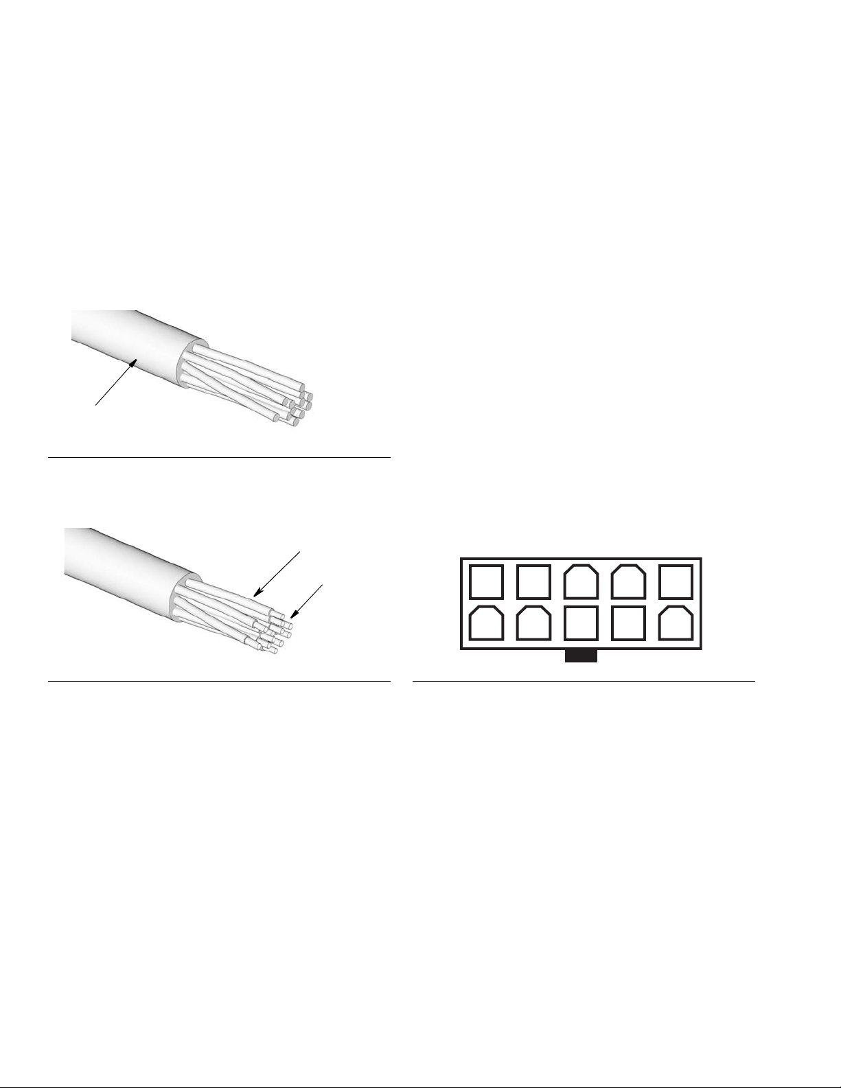
Connector Installation
1. Remove 2 to 3 inches of the outer insulation from
one end of a user supplied cable (a) as shown in
F
IG. 1.
NOTE: The cable should contain multicolored wires
to ensure easy and accurate component installation.
.
FIG. 1
2. Strip each wire (b) to be crimped so approximately
0.08 - 0.012 inches (2- 3 mm) of bare wire (c) is
showing as shown in F
IG. 2.
4. (See F
5. Firmly squeeze the crimp tool to crimp and secure
6. Repeat steps 3 - 5 until all wires are crimped with
7. Insert pins into connector. When looking at the con-
IG. 2) Insert stripped end (c) of wire (b) into
pin. The edge of the insulation should be about 0.05
- 0.09 inches (1.2- 2.2 mm) into the pin.
NOTE: To ensure proper fit, ensure that the bare
wire and the insulator are crimped separately.
• If the insulation is too deep, the pin will not
make contact with the wire.
• If the insulation is not deep enough, the pin may
not fit inside the connector properly.
the pin to the wire.
pins.
nector, be sure you are plugging in pins in the correct side. Refer to F
pin locations. Use the Wiring Key provided on page
4 to identify related components.
IG. 3 for correct orientation and
FIG. 2
3. Insert one of the pins into the appropriately sized
slot of the hand crimp tool.
NOTE:
• A hand crimp tool is available from Graco. Order
part number 16T671.
• The pin must be placed all the way into the
crimper in the correct orientation.
FIG. 3
NOTE:
• The second column of the Wiring Key Table is
provided for the user to record the wire color
assigned to each component.
• There are 10 available PIN locations in the connector. Only use the pin locations necessary for
your installation. Refer to the Connector Identification Label and Wiring Key provided on page
4.
Page 3

Component Wiring
a
b
c
1 2 3 4 5
6 7 8 9 10
M
9A Fuse
+
-
V
Instructions
1. Before connecting wires to components verify the
Connector end of the cable is NOT plugged into the
GLC2200 controller.
2. Remove 2 to 3 inches of the outer insulation (a)
from bare end of the cable as shown F
.
FIG. 4
3. Strip each wire (b) you are using for the installation
as shown in F
NOTE: It is not necessary to strip all of the wires;
only strip the wires needed for your installation.
IG. 5.
IG. 4.
4. Using the Wiring Key Table, connect components to
wires matching each wire color and pin location.
Verify all negative and positive wire colors are correctly assigned.
NOTE: The second column of the Wiring Key Table
is provided for the user to record the wire color
assigned to each component.
5. Plug connector into the GLC2200 unit matching pin
numbers to Connector Identification Label.
NOTE: The connector can only be plugged into the
GLC2200 one way. The clip (c) should be facing
down when the connector is correctly oriented.
FIG. 6
FIG. 5
Wiring Diagram
FIG. 7
M = Motor pump power or solenoid
V = Electric vent valve for injector-based systems
3A2992B 3
Page 4

Wiring Key
9A 2A
P/C
+9V
+30V
1
2
Wire
Pin
1Pump
2Alarm
3Low Level
4 Pressure Cycle Switch
5 Voltage Input
6Pump
7Alarm
8Low Level
9 Pressure Cycle Switch
10 Voltage Input
* Use this column to record the wire color assigned to
each component used for your installation.
Color* Description
+/-
-
-
-
-
+
+
+
+
+
Parts
Connector Identification Label
(Adhered to GLC2200 controller)
PIN12345
PIN678910
Qty
Ref Description 24P686 24P687
PIN, socket, 18-24 AWG,
1
crimp, gold
CONNECTOR, receptacle,
2
dual, 10 position
12 60
15
Accessories
Crimping Tool - 16T671
All written and visual data contained in this document reflects the latest product information available at the time of publication.
GRACO INC. AND SUBSIDIARIES • P.O. BOX 1441 • MINNEAPOLIS MN 55440-1441 • USA
Copyright 2012, Graco Inc. All Graco manufacturing locations are registered to ISO 9001.
Graco reserves the right to make changes at any time without notice.
For patent information, see www.graco.com/patents.
Original instructions. This manual contains English. MM 3A2992
Graco Headquarters: Minneapolis
International Offices: Belgium, China, Japan, Korea
www.graco.com
December 2013
 Loading...