

Page 1
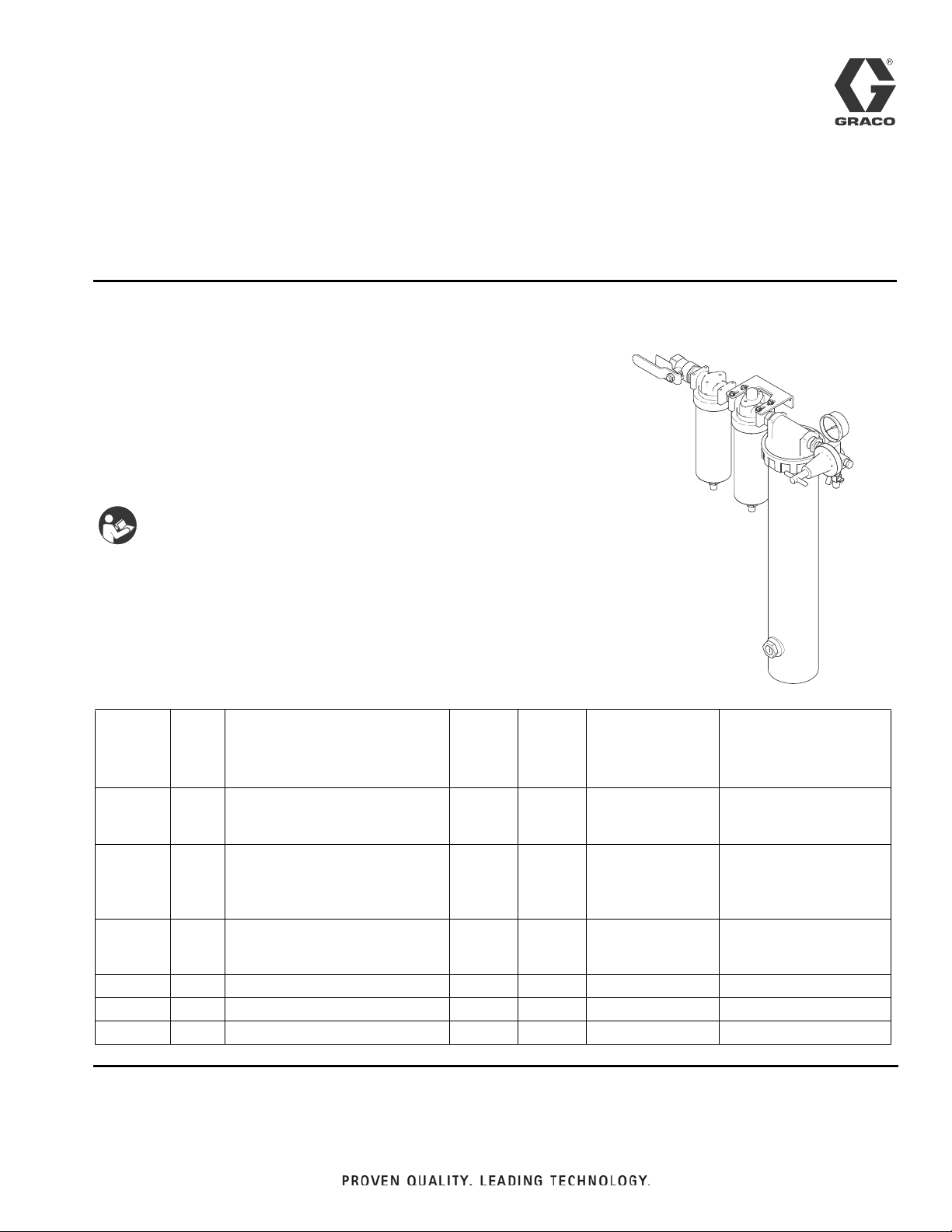
Instructions - Parts List
Model 234401 shown
ti22155a
Desiccant Air
Drying System
Model 234401, Series D
Maximum Operating Pressure 160 psi (1.1 MPa, 11 bar)
Maximum Temperature 150° F (65° C)
Model 24M178, Series B
Maximum Operating Pressure 175 psi (1.2 MPa, 12 bar)
Maximum Temperature 150° F (65° C)
Important Safety Instructions
Read all warnings and instructions in this manual.
Save these instructions.
Includes:
309921N
EN
Part No. Series Description
234402 B Stage 1 - Air Filter with automatic
drain. Removes water and contaminants down to 3 microns.
234397 B Stage 2 - Coalescer with auto-
matic drain. Removes oil and
sub-micronic particles down to
1 micron.
234404 B Stage 3 - Desiccant Housing
Removes uncondensed moisture.
288787 A Self Relieving Air Regulator
288810 A Silica Gel Desiccant (5 lb. can)
288798 A Shut-off Valve
Air
Air Inlet
npt(f)
1/2 in. 1/2 in. 100 175 (1.2, 12)
1/2 in. 1/2 in. 83 175 (1.2, 12)
3/4 in.,
reduced
to 1/2 in.
3/8 in. 1/4 in. 100 160 (1.1, 11)
Outlet
npt(f)
3/4 in.,
reduced
to 3/8 in.
Air Flow Capacity
(CFM)
at 100 psi
(0.7 MPa, 7 bar)
30 175 (1.2, 12)
Maximum Operating
Pressure, psi (MPa, bar)
Page 2
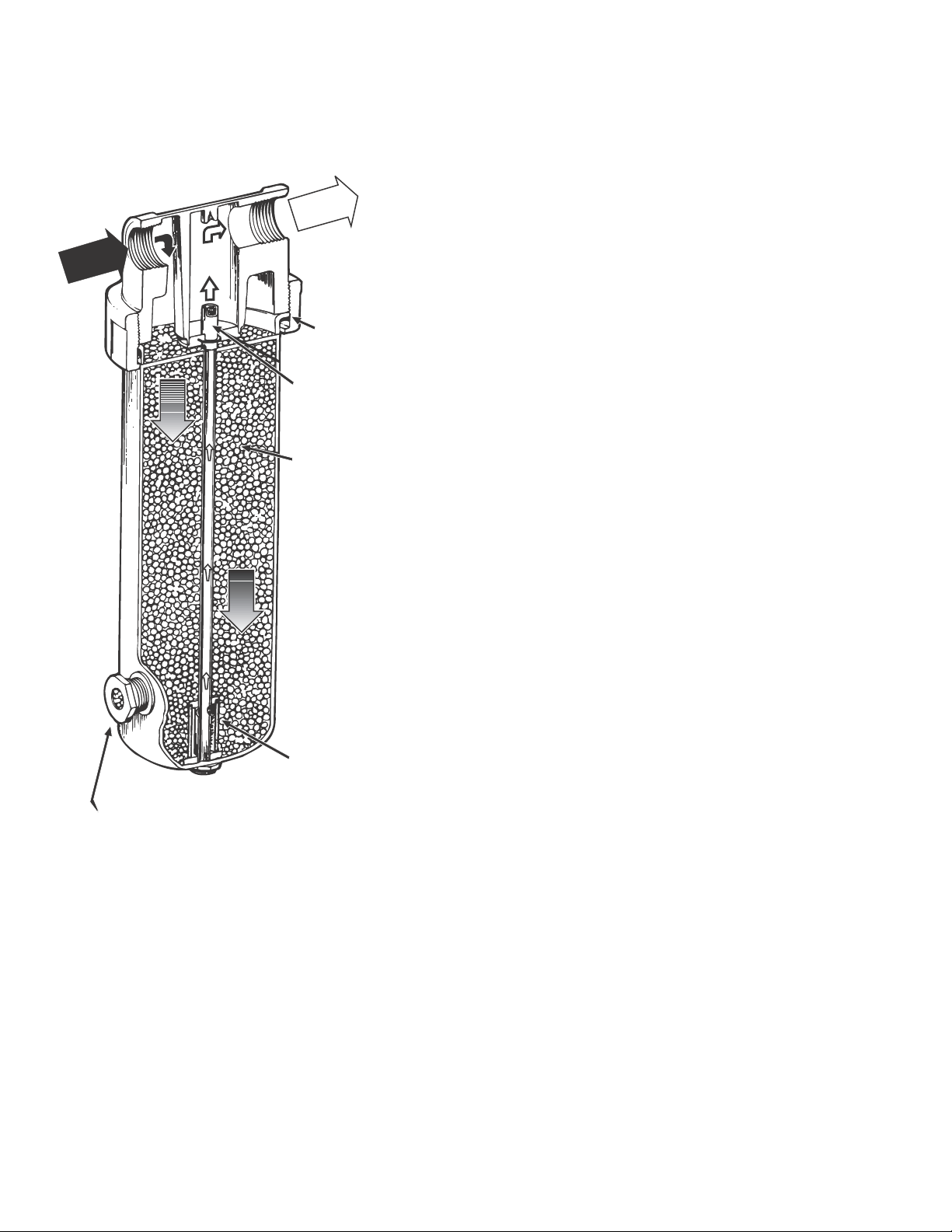
How Desiccant Air Drying System Works
WET AIR
IN
DRY AI R
OUT
Quick-remove
flange
Built-in screen
prevents desiccant
from going down tube
when refilled
288810 Blue silica gel
desiccant beads turn
pink when saturated.
Element prevents any
desiccant dust from
traveling downstream
Built-in sight glass allows
easy monitoring of desiccant
color change
How Desiccant Air Drying System Works
After the moisture has been removed, the dry air passes
through an element, up the center tube, and out the outlet port. As long as the desiccant is replaced at saturation point and your compressed air is not exposed to a
temperature below the dew point, your equipment will
receive dry, moisture-free air.
As the desiccant becomes saturated with moisture, the
dew point begins to rise. This is evident when the desiccant changes color from blue to pink, indicating the need
for desiccant replacement. Refer to Desiccant Change-
out, page 9.
When air is compressed, the temperature of the air
increases, as does its capacity to hold moisture. As the
hot, moist air travels down through the lines, it cools,
allowing the moisture to condense. Filters, drain traps,
and driplegs only remove liquid condensation. The
Dryaire Desiccant Air Drying System removes liquid
condensation, residual water vapor and aerosols.
As the wet compressed air flows through the inlet port
and down the bed of desiccant, the desiccant beads
absorb the water vapor and aerosols and can reduce
the air humidity down to a -40°F (-40°C) pressure dew
point.
2 309921N
Page 3
Installation
2
4
6
8
1
1
1
1
2
4
6
8
1
SATURA
TED
NORMA
DESICCANT
¨
2
4
6
8
1
1
1
1
2
4
6
8
1
Membrane air
drying system
Desiccant air
drying system
Ball Valve
Drain Valve
Drain
Leg
Air Control unit
or Air Filter
1/2 in.
(13 mm) drops
Main Air Line
3/4 in. (19 mm) minimum
1-1/4 in. (32 mm) optimum
S
l
o
p
e
s
d
o
w
n
a
n
d
a
w
a
y
R
e
c
o
m
m
e
n
d
e
d
4
i
n
.
(
1
1
7
m
m
)
d
r
o
p
i
n
5
0
f
t
(
1
5
.
2
4
m
)
g
a
l
v
a
n
i
z
e
d
p
i
p
e
r
e
c
o
m
m
e
n
d
e
d
)
Coalescer
Air
Filter
Compressor
Flexible hose
between compressor
and stand pipe
1
5
-
2
0
f
t
.
(
4
.
6
-
6
.
1
m
)
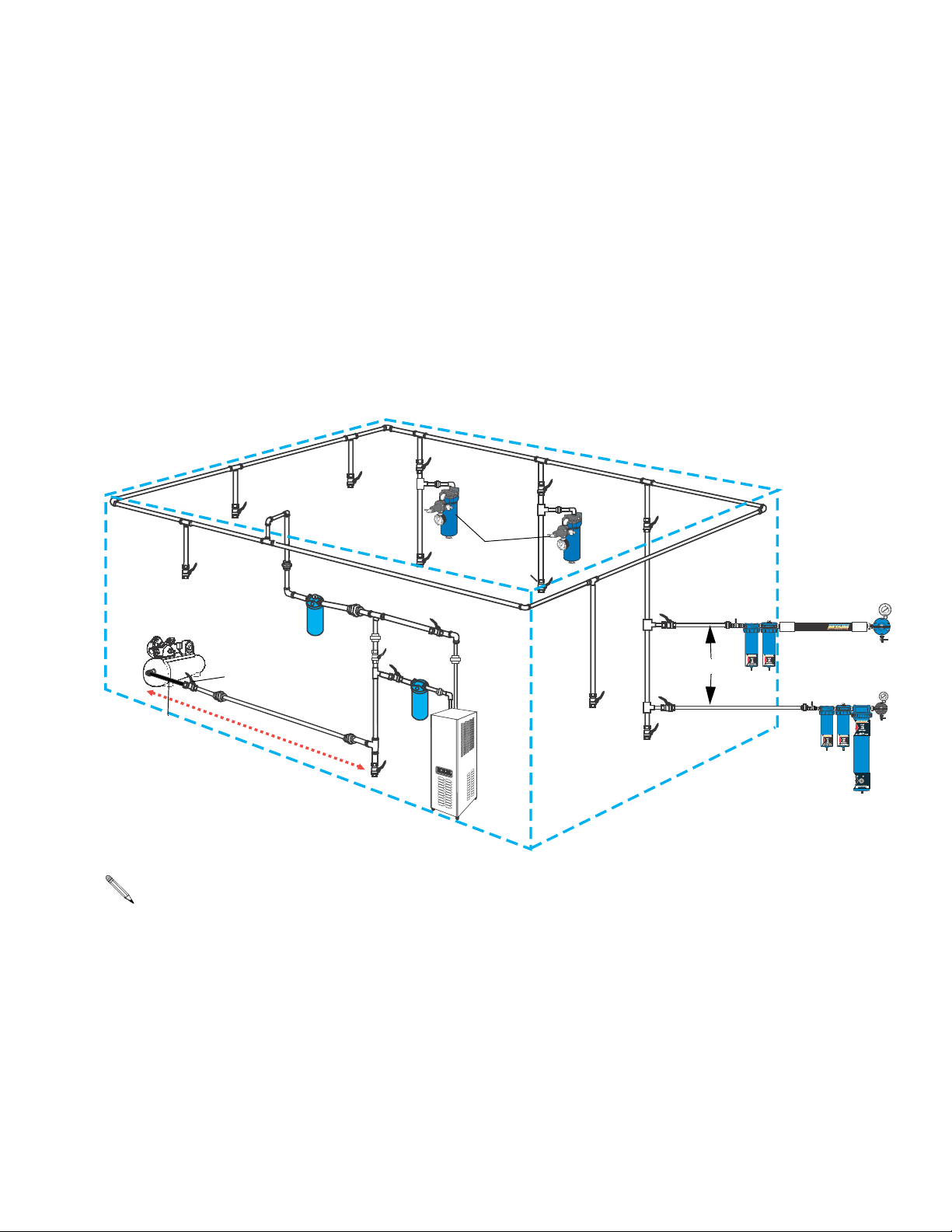
• Main Air Line stand pipe should not be smaller than compressor outlet size.
• A minimum of 25 ft. (7.62 m) from compressor to first filter outlet is required to cool air [50 ft. (15.24 m) optimum]
OR
Main Air
Shut-off Valve
Installation
1. Before installing air line components, blow out the
pipe line to remove debris. Be sure air to the regulator is clean. Erratic operation or loss of regulation is
usually caused by dirt in the regulator.
2. Install the Air Drying System as close as possible to
the equipment it serves. Use template 289185, provided, to position system.
Shop Air Piping Layout
3. Install air shut-off valve 288798 upstream from the
air system to isolate it for service.
4. Install system so air flows through filters in the direction noted on top of filter.
5. A minimum 1/2 in. npt piping is recommended.
Avoid using too many fittings, couplings, etc., which
will restrict air flow.
309921N 3
Page 4
Installation
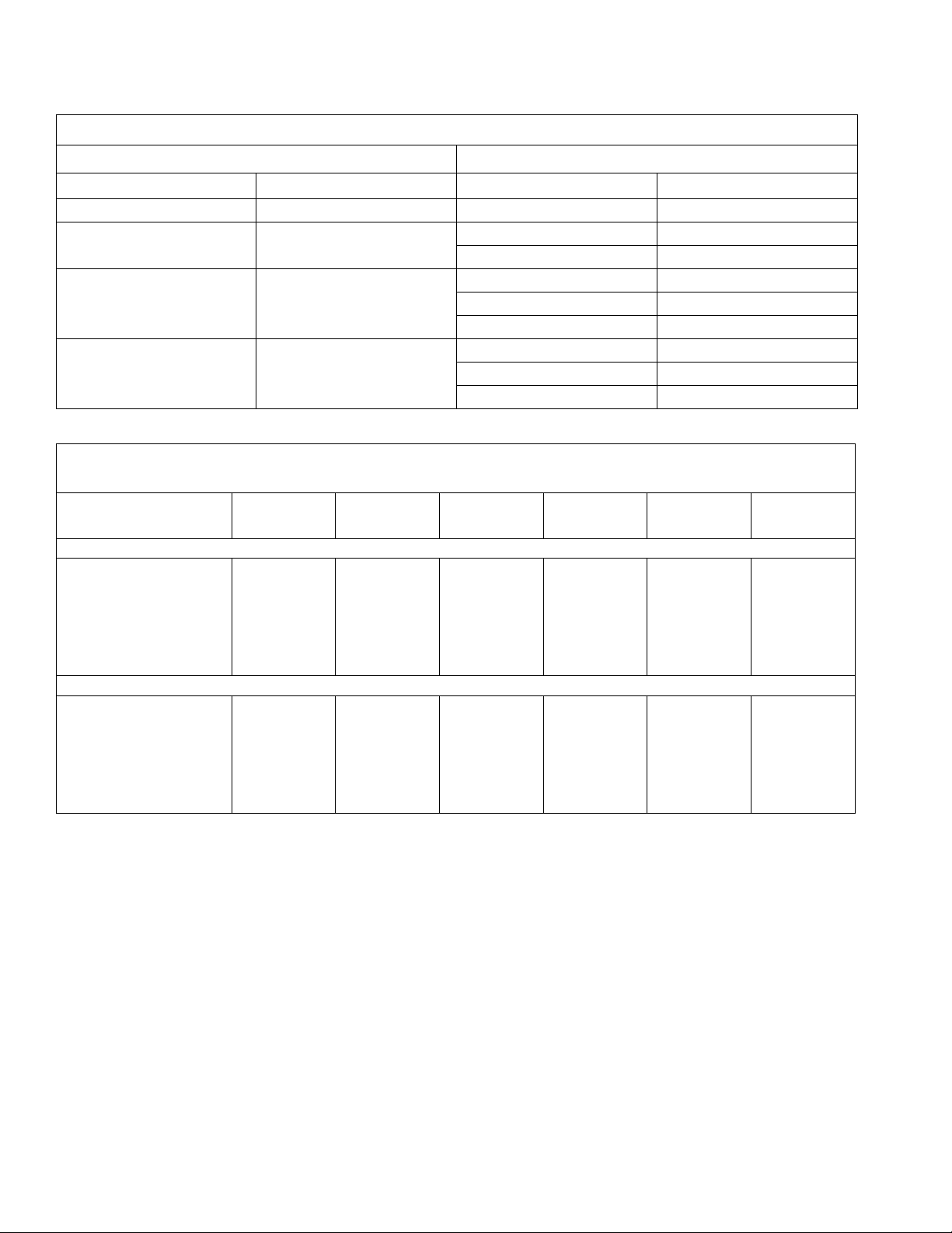
Size Capacity Length Size
1-1/2 - 2 HP 6 - 9 CFM any 3/4 in. (19 mm)
3 - 5 HP 12 - 20 CFM Up to 200 ft (61 m) 3/4 in. (19 mm)
5 - 10 HP 20 - 40 CFM Up to 100 ft (30.5) 3/4 in. (19 mm)
10 - 15 HP 40 - 60 CFM Up to 100 ft (30.5) 3/4 in. (19 mm)
Air Hose Inside
Diameter
1/4 in. (6.4 mm)
40 psi (276 kPa, 2.8 bar)
50 psi (345 kPa, 3.4 bar)
60 psi (414 kPa, 4.1 bar)
70 psi (483 kPa, 4.8 bar)
80 psi (552 kPa, 5.5 bar)
90 psi (621 kPa, 6.2 bar)
5/16 in. (7.9 mm)
40 psi (276 kPa, 2.8 bar)
50 psi (345 kPa, 3.4 bar)
60 psi (414 kPa, 4.1 bar)
70 psi (483 kPa, 4.8 bar)
80 psi (552 kPa, 5.5 bar)
90 psi (621 kPa, 6.2 bar)
Minimum Pipe Size Recommendations
Compressor Main Air Line
Over 200 ft (61 m) 1 in. (25.4 mm))
Over100-200ft(30.5-61m) 1 in. (25.4 mm)
Over 200 ft (61 m) 1-1/4 in. (31.8 mm)
Over100-200ft(30.5-61m) 1-1/4 in. (31.8)
Over 200 ft (61 m) 1-1/2 in. (38.1)
Air Pressure Drop Through Hose, by hose length and ID
psi (Kpa, bar)
4 ft.
(1.22 m)
6 (41, .4)
7.5 (52, .5)
9 (62, .6)
10.75 (74, .7)
12.25 (84, .8)
14 (97, 1)
2.25 (16, .2)
3 (21, .2)
3.75 (26, .3)
4.5(31, .3)
5.5 (38, .4)
6.5 (45, .4)
10 ft.
(3.05 m)
8 (55, .6)
10 (69, .7)
12.5 (86, .9)
14.5 (100, 1)
16.5(114,1.1)
18.75 (129, 1.3)
2.75 (19, .2)
3.5 (24, .2)
4.5 (31, .3)
5.25 (36, .4)
6.25 (43, .4)
7.5 (52, .5)
15 ft.
(4.6 m)
9.5 (66, .7)
12 (83, .8)
14.5 (100, .1)
17 (117, 1.2)
19.5 (134, 1.3)
22 (152, 1.5)
3.25 (22, .2)
4 (28, .3)
5 (34, .3)
6 (41, .4)
7 (48, .5)
8.5 (59, .6)
20 ft.
(6.1 m)
11 (76, .8)
14 (97, 1)
16.75(115,1.2)
19.5 (134, 1.3)
22.5 (155, 1.6)
25.25 (172, 1.7)
3.5 (24, .2)
4.5 (31, .3)
5.5 (38, .4)
6.75 (47, .5)
8 (55, .6)
9.5 (66, .7)
25 ft.
(7.62 m)
12.75 (88, 0.9)
16 (110, 1.1)
19 (131, 1.3)
22.5 (155, 1.6)
25.5 (176, 1.8)
29 (200, 2)
4 (28, .3)
5 (34, .3)
6 (41, .4)
7.25 (50, .5)
8.75 (60, .6)
10.5 (72, .7)
50 ft.
(15.24 m)
24 (165, 1.7)
28 (193, 1.9)
31 (214, 2.1)
34 (234, 2.3)
37 (255, 2.6)
39.5 (169, 2.7)
8.5 (59, .6)
10 (69, .7)
11.5 (79, .8)
13 (90, .9)
14.5 (100, 1)
16 (110, 1.1)
4 309921N
Page 5

Installation
309921N 5
Page 6

Operation
Operation
WARNING
Do not exceed the Maximum Incoming Air Pressure
of the equipment. Over pressurizing can cause
component rupture and serious injury.
Model 234401, Series D
1. Attach air hose(s) to air regulator outlet valve
289165.
2. Attach air hose to main shut-off valve 288798.
3. Open main shut-off valve 288798.
4. Turn the T-hand adjusting screw in or out to adjust
regulator to desired setting.
5. Open outlet valve 289165 to supply air to spray
guns or tool.
6. With air flowing, readjust air pressure regulator if
necessary.
7. Turn off unit when not in use. Follow Pressure
Relief Procedure, page 8.
Model 24M178, Series B
1. Attach air hose(s) to outlet elbow fitting 120375.
2. Attach air hose to inlet elbow fitting C19024.
Automatic Drain
The automatic drain is equipped with a float actuated
device which automatically ejects liquid contaminates
under pressure.
Coalescer Pressure Drop Indicator
The differential pressure drop indicator provides early
detection of a clogged coalescing filter element. As the
filter element becomes clogged, the red indicator starts
to rise while air is flowing through the unit. When the
pressure drop across the element reaches 10-12 psi
(69-83 kPa, 0.7-0.8 bar), the red indicator will be in full
view, and the element should be replaced. Failure to
replace the element when the pressure drop exceeds
10 psi (69 kPa, 0.7 bar) will affect your air quality and
tool efficiency.
3. Open main shut-off valve 288798.
4. Turn off unit when not in use. Follow Pressure
Relief Procedure, page 8.
6 309921N
Page 7

Operation
288789
288787
234404
234397
234402
288798
289165
Part No. Description
234402 Air Filter with auto drain; see Manual
309919 for parts information
234397 Coalescer with auto drain; see Manual
309919 for parts information
234404 Desiccant Housing
288787 Air Regulator, self relieving
288789 Nipple with screen
288798 Shut-off Valve
289165 Regulator Outlet Valve
Model 234401
Model 24M178
288798
Part No. Description
234402 Air Filter with auto drain; see Manual
309919 for parts information
234397 Coalescer with auto drain; see Manual
309919 for parts information
234404 Desiccant Housing
288789 Nipple with screen
288798 Shut-off Valve
C19024 Elbow Fitting
120375 Elbow Fitting
C19024
234397
234402
234404
288789
120375
ti22157a
ti22156a
309921N 7
Page 8

Maintenance and Repair
Pressure Relief Procedure
WARNING
To avoid injury, relieve air and fluid pressure before
checking, cleaning, or repairing the equipment.
The following is a basic pressure relief procedure. Be
sure to follow the specific pressure relief procedure in
your spray gun and/or fluid supply equipment manuals.
1. Close the main air shut-off valve.
2. Trigger the gun or dispense valve and open any
drain valves to relieve pressure.
Maintenance and Repair
• Relieve the pressure before cleaning, checking
or repairing. Follow Pressure Relief Proce-
dure, above.
Coalescer 234397, Series B
NOTE: It is recommended that Air Filter 234402 be
installed upstream of the coalescing filter to
remove 3 micron and larger size particles and separate large droplets of moisture from the air line.
CAUTION
Never let the liquid level in the bowl reach the base of
the coalescing element.
See Manual 309919 for operation, cleaning, and parts
information.
• Check system at least once per shift to ensure
proper drainage.
• A supply of low flow/low humidity air will provide longer desiccant life.
Air Filter 234402, Series B
To maintain maximum filtering efficiency and avoid
excessive pressure drop, the filter must be kept clean.
See Manual 309919 for cleaning and parts information.
8 309921N
Page 9
Maintenance and Repair
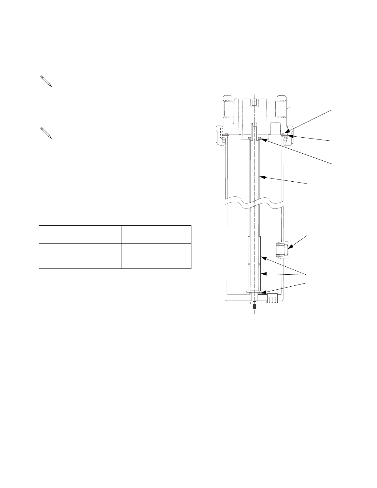
289189
288794
288793
288795
289186
289187 (2)
289188
Desiccant Housing 234404, Series B
NOTE: Always install a moisture filter, to remove
bulk fluids, and a coalescing filter, to remove oil,
upstream of the desiccant housing. Desiccant
coated with oil will not absorb moisture.
Desiccant Changeout
NOTE: Desiccant beads are non-toxic and
non-flammable.
The desiccant gradually changes color from blue to pink,
indicating it has absorbed moisture to the saturation
point and needs to be regenerated or replaced.
• To regenerate Silica Gel desiccant, heat desiccant
for 4 hours at 275°F (135°C).
• To replace desiccant, order desired part no. from the
following chart.
5. Refill bowl with new or regenerated desiccant. See
Desiccant Changeout. Desiccant Housing 234404
holds 5 lb. of desiccant.
6. Reassemble bowl to cover, making sure that o-ring
289186 is in place in cover.
Color
Desiccant Part No.
288810 Silica Gel (5 lb)
288823 Silica Gel (four 5 lb
cans)
Desiccant Housing Disassembly
1. Follow the Pressure Relief Procedure, page 8.
2. Unscrew the metal collar holding the desiccant bowl
to cover. Remove bowl and collar.
3. Dump old desiccant out of bowl.
4. If the pressure drop across the dryer has become
unacceptable, the bronze element in the bottom of
the bowl may be clogged. To remove clog:
a. Place a blow gun at the top of the tube and blow
air through the flow tube.
b. If element replacement is needed: disassemble
flow tube from the bowl by removing the end
cap and nut from the bottom of the bowl.
when fresh
Blue Pink
Blue Pink
Color when
saturated
Part No. Description
288793 Flow Tube Assy., includes flow tube, nut,
o-ring, filter elements and retainers
289186 O-Ring
288794 Gasket
289189 O-Ring
289187 Filter Element
289188 O-Ring
288795 Sight Glass
288810 Desiccant, silica gel (5 lb)
288823 Desiccant, silica gel (four 5 lb cans)
c. Turn the flow tube (hand tight) counter clock-
wise to remove it, then replace elements.
d. Reassemble in reverse order.
309921N 9
Page 10
Maintenance and Repair
2
0
4
0
60
80
100
120
1
40
160
2
4
6
8
10
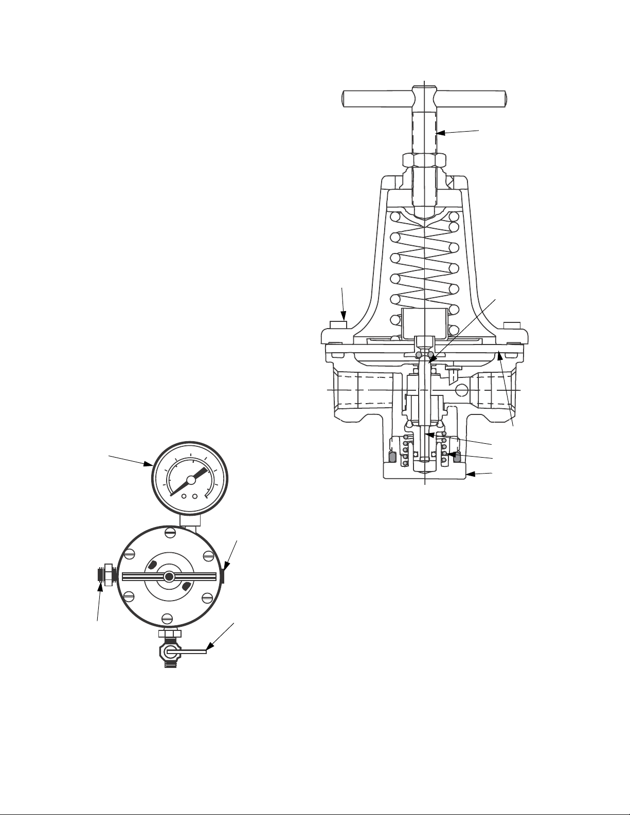
Air Regulator Assembly
for Desiccant Air Drying System
289340
288797
289149
289165
289190
288796
289191
(spring)
Screws (6)
Valve
Bottom Plug
Diaphragm
Self-Relieving Air Regulator 288787
Be sure air to the regulator is clean. Erratic operation or
loss of regulation is usually caused by dirt in the regulator.
Cleaning
1. Follow the Pressure Relief Procedure, page 8.
2. Remove bottom plug, spring, and valve.
3. Remove six screws, and separate regulator body.
4. Clean all parts with denatured alcohol. Wipe off seat
and blow out body.
5. Inspect parts for damage and replace as needed. To
replace the valve and diaphragm, order Repair Kit
288796.
6. Reassemble parts and screw them into the regulator before tightening the bottom plug. Make sure the
valve, diaphragm and spring are center aligned.
Part No. Description
289340 Air Pressure Gauge
289149 Plug
288796 Diaphragm/Valve Repair Kit
289190 T-handle Adjusting Screw
289191 Spring
288797 Nipple, 3/8 in. x 3/8 in.
289165 Shut-off Valve
10 309921N
Page 11

Maintenance and Repair
309921N 11
Page 12

Graco Standard Warranty
Graco warrants all equipment referenced in this document which is manufactured by Graco and bearing its name to be free from defects in
material and workmanship on the date of sale to the original purchaser for use. With the exception of any special, extended, or limited warranty
published by Graco, Graco will, for a period of twelve months from the date of sale, repair or replace any part of the equipment determined by
Graco to be defective. This warranty applies only when the equipment is installed, operated and maintained in accordance with Graco’s written
recommendations.
This warranty does not cover, and Graco shall not be liable for general wear and tear, or any malfunction, damage or wear caused by faulty
installation, misapplication, abrasion, corrosion, inadequate or improper maintenance, negligence, accident, tampering, or substitution of
non-Graco component parts. Nor shall Graco be liable for malfunction, damage or wear caused by the incompatibility of Graco equipment with
structures, accessories, equipment or materials not supplied by Graco, or the improper design, manufacture, installation, operation or
maintenance of structures, accessories, equipment or materials not supplied by Graco.
This warranty is conditioned upon the prepaid return of the equipment claimed to be defective to an authorized Graco distributor for verification of
the claimed defect. If the claimed defect is verified, Graco will repair or replace free of charge any defective parts. The equipment will be returned
to the original purchaser transportation prepaid. If inspection of the equipment does not disclose any defect in material or workmanship, repairs will
be made at a reasonable charge, which charges may include the costs of parts, labor, and transportation.
THIS WARRANTY IS EXCLUSIVE, AND IS IN LIEU OF ANY OTHER WARRANTIES, EXPRESS OR IMPLIED, INCLUDING BUT NOT LIMITED
TO WARRANTY OF MERCHANTABILITY OR WARRANTY OF FITNESS FOR A PARTICULAR PURPOSE.
Graco’s sole obligation and buyer’s sole remedy for any breach of warranty shall be as set forth above. The buyer agrees that no other remedy
(including, but not limited to, incidental or consequential damages for lost profits, lost sales, injury to person or property, or any other incidental or
consequential loss) shall be available. Any action for breach of warranty must be brought within two (2) years of the date of sale.
GRACO MAKES NO WARRANTY, AND DISCLAIMS ALL IMPLIED WARRANTIES OF MERCHANTABILITY AND FITNESS FOR A
PARTICULAR PURPOSE, IN CONNECTION WITH ACCESSORIES, EQUIPMENT, MATERIALS OR COMPONENTS SOLD BUT NOT
MANUFACTURED BY GRACO. These items sold, but not manufactured by Graco (such as electric motors, switches, hose, etc.), are subject to
the warranty, if any, of their manufacturer. Graco will provide purchaser with reasonable assistance in making any claim for breach of these
warranties.
In no event will Graco be liable for indirect, incidental, special or consequential damages resulting from Graco supplying equipment hereunder, or
the furnishing, performance, or use of any products or other goods sold hereto, whether due to a breach of contract, breach of warranty, the
negligence of Graco, or otherwise.
FOR GRACO CANADA CUSTOMERS
The Parties acknowledge that they have required that the present document, as well as all documents, notices and legal proceedings entered into,
given or instituted pursuant hereto or relating directly or indirectly hereto, be drawn up in English. Les parties reconnaissent avoir convenu que la
rédaction du présente document sera en Anglais, ainsi que tous documents, avis et procédures judiciaires exécutés, donnés ou intentés, à la suite
de ou en rapport, directement ou indirectement, avec les procédures concernées.
Graco Phone Numbers
For the latest information about Graco products, visit www.graco.com.
For patent information, see www.graco.com/patents.
TO PLACE AN ORDER, contact your Graco distributor or call to identify the nearest distributor.
Phone: 612-623-6921 or Toll Free: 1-800-328-0211, Fax: 612-378-3505
All written and visual data contained in this document reflects the latest product information available at the time of publication.
GRACO INC. AND SUBSIDIARIES • P.O. BOX 1441 • MINNEAPOLIS MN 55440-1441 • USA
Copyright 2003, Graco Inc. All Graco manufacturing locations are registered to ISO 9001.
Graco reserves the right to make changes at any time without notice.
Original instructions. This manual contains English. MM 309921
Graco Headquarters: Minneapolis
International Offices: Belgium, China, Japan, Korea
www.graco.com
Revision N, October 2013
 Loading...