

Page 1
Instructions - Parts
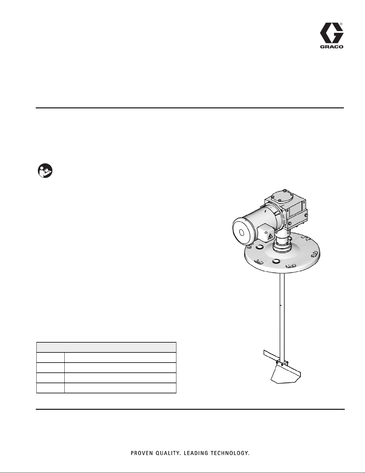
Agitator
Conversion Kit
For converting agitator 1.5.5B to 24K360. For professional use only.
Part 24K408
Important Safety Instructions
Read all warnings and instructions in this manual and
the Gusmer-Decker RC system manuals. Save all
instructions.
3A1931A
ENG
Contents
Related Manuals ............................1
Installation ................................2
Remove Agitator 1.5.5B ....................2
Install Kit 24K408 Components ..............3
Parts .....................................5
Technical Data .............................5
Graco Standard Warranty ....................6
Graco Information ..........................6
Related Manuals
Manuals are available at www.graco.com. Related manuals
listed are in English.
Gusmer-Decker RC Manuals
Part Description
312750 Gusmer-Decker RC Operation
312751 Gusmer-Decker RC Repair and Parts
313264 Gusmer-Decker RC Electrical Diagrams
ti17565a
Kit is shown assembled with agitator motor, gear
reducer, and tank lid for reference only
Page 2
Installation
Installation
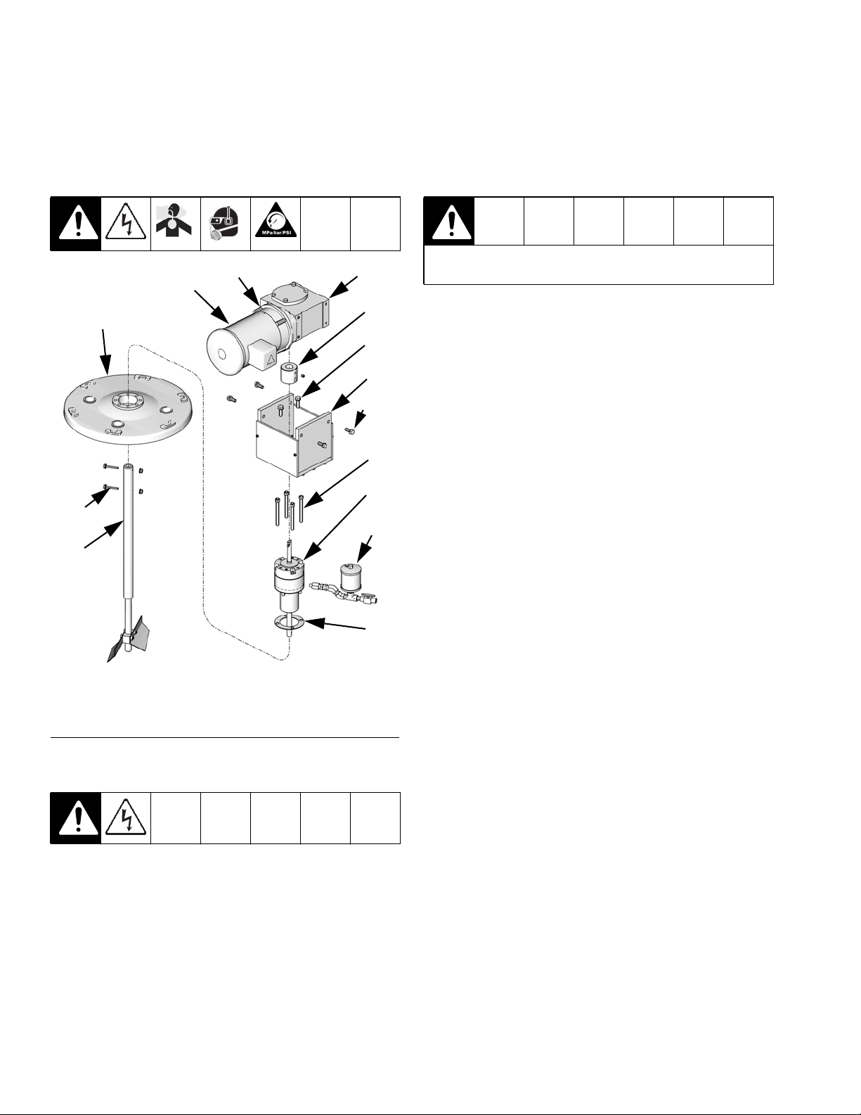
Remove Agitator 1.5.5B
A12◆
A13◆
From Tank
Assembly◆
A01◆
A02
A03
A04
To prevent injury, use proper lifting equipment to raise
the tank lid and agitator assembly.
NOTE: The tank lid and agitator assembly weighs
approximately 100 lb (45 kg).
4. Loosen tank lid clamps then remove tank lid and
agitator assembly from tank.
A05◆
A06
A07
A10
A11
ti17567a
◆ Items are needed during 24K408 installation.
All other items can be discarded.
FIG.1
1. Perform the Shutdown and Pressure Relief Procedures in the Gusmer-Decker RC system manual.
A08
A09
5. Remove two hex head cap screws (A10) then
remove agitator shaft (A11) from agitator
housing (A07).
6. Remove lube cup and fittings assembly (A08) from
the agitator housing (A07).
NOTE: Before performing the following step, use a small
piece of masking tape to note the location of the motor
relative to the tank lid. This will ensure the motor (A13)
is re-installed in the proper orientation.
7. Remove four screws (A12) then remove agitator
motor (A13) from gear reducer (A01).
8. Remove four screws and washers (A05) then
remove gear reducer (A01) from base (A04).
9. Loosen coupling set screw then remove
coupling (A02) from gear reducer.
10. Remove two hex head cap screws (A03) then
remove base (A04) from agitator housing (A07).
11. Remove four socket head cap screws (A06) then
remove agitator housing (A07) and seal (A09) from
tank lid.
NOTE: Prior to beginning the Install Kit 24K408 Com-
2. Disconnect incoming power from agitator motor.
3. Disconnect all air lines from lid.
2 3A1931A
ponents procedure, discard or set aside all items
except those noted in FIG. 1. This will prevent confusing
parts from 1.5.5B with parts from 24K408.
Page 3

Install Kit 24K408 Components
Installation
4. Insert agitator shaft (13) through housings (4, 12)
then use snap ring pliers to install snap ring (14)
onto groove in shaft (13).
From Tank
Assembly
13
A13◆
A12◆
24
10
A01◆
11
A05◆
14
17, 18
16
5. Rotate agitator shaft (13) so that flat spot for set
screw is viewable through the opening in the
housing (4).
6. Apply sealant (25) to set screw (24) then insert set
5
6
1
3
7
4
9
screw into coupling (7).
7. Install coupling (7) onto agitator shaft (13).
8. Verify the set screw in the coupling (7) is located
over the flat spot on the agitator shaft then temporarily tighten the set screw.
NOTE: In the following step, be sure to install base (1)
so that motor can be installed in the orientation noted
when it was removed. The opening in the base is
off-center so the gear reducer will only fit in the base
one way.
9. Place spacer (3) onto housing (4) then use four
screws (11) to install base (1) onto spacer and
housing assembly. Torque screws (11) to 8-12 ft-lb
(11-16 N•m).
NOTE: In the following step, the face of the coupling (5)
should be flush with the end of the gear reducer
shaft (A01).
10. Install coupling (5) and alignment disk (6) onto gear
12
reducer shaft (A01). Apply sealant (25) to set screw
15
ti17568a
◆ Items are from agitator
assembly 1.5.5B.
FIG.2
1. Perform the Remove Agitator 1.5.5B procedure on
page 2.
2. Use four screws (16) to install housing (12) and
gasket (15) onto tank lid. Torque screws (16) to
30-45 ft-lb (41-61 N•m).
3. With spacer (9) installed over seal (10), use four
screws (18) and washers (17) to install housing (4)
onto other housing (12). Torque screws (18) to
75-80 in-lb (8.5-9.0 N•m).
3A1931A 3
in coupling (5) then tighten set screw.
11. While rotating the agitator shaft (13) back and forth,
insert gear reducer (A01) into base (1) then install
screws and washers (A05). Torque screws (A05) to
30-45 ft-lb (41-61 N•m).
Page 4

Installation
NOTE: In the following step, the agitator shaft must be
rotated by turning the gear reducer input sleeve
shaft (A01a). Attempting to rotate the agitator shaft by
rotating the agitator shaft itself will not work. This is due
to the design of the gear reducer. See FIG.3.
A01a
A01
A13
A12
ti17566a
FIG. 3: Gear Reducer Input Sleeve Shaft
12. Rotate the gear reducer input sleeve shaft (A01a) to
turn the agitator shaft so that the set screw (24) in
the coupling (7) is visible through the opening in the
housing (4).
13. Loosen the set screw (24) in the coupling (7), then
slide the coupling (7) against the other coupling (5)
and tighten the set screw (24).
NOTE: The previous step ensures the two couplings are
fully engaged.
14. Use screws and washers (A12) to install agitator
motor (A13) onto gear reducer assembly (A01).
To prevent injury, use proper lifting equipment to raise
the tank lid and agitator assembly.
NOTE: The tank lid and agitator assembly weighs
approximately 100 lb (45 kg).
15. Install agitator and tank lid assembly onto tank and
tighten the lid clamps.
16. Connect incoming power to the agitator motor.
17. Connect air lines to tank lid.
4 3A1931A
Page 5

Parts
Parts
◆
13
24
10
◆ Items are not included with kit 24K408.
Shown for reference only.
ti17568a
◆
11
14
17, 18
16
12
15
Ref Part Description Qty
1 24K359 BASE, agitator plate assy 1
3 15V746 SPACER, agitator motor 1
4 15Y358 HOUSING, upper, agitator, ASME,
5
5 121963 COUPLER, agitator motor, 1 in. 1
6
6 122760 COUPLING, alignment, disk, TPE 1
7 122761 HOSE, alignment, hub 1
8 122774 BEARING, ball, 3/4 bore x
1
9 15Y360 SPACER, seal, shaft, ASME, agita-
◆
10 122772 SEAL, 0.875 x 1.125, PTFE 1
11 --- SCREW, cap, sch 4
12 16K284 HOUSING, agitator to lid 1
13 24K358 BLADE, agitator assy 1
3
14 122776 RING, ret, ext, 0.750, ms 1
15 16K285 GASKET, agitator to lid 1
7
16 --- SCREW, cap, sch 4
17 --- WASHER, lock, spring (hi-collar) 4
4
18 --- SCREW, cap, sch 4
24 --- SCREW, socket head set screw,
9
25 113500 ADHESIVE, anaerobic, 0.017 fl oz,
--- Not for sale.
1
electric
2
1-3/4 dia. x 1/2
1
tor
1
5/16-18 x 0.75
1
0.5 ml
Technical Data
See Gusmer-Decker RC system manual for technical
data.
3A1931A 5
Page 6

Graco Standard Warranty
Graco warrants all equipment referenced in this document which is manufactured by Graco and bearing its name to be free from defects in
material and workmanship on the date of sale to the original purchaser for use. With the exception of any special, extended, or limited warranty
published by Graco, Graco will, for a period of twelve months from the date of sale, repair or replace any part of the equipment determined by
Graco to be defective. This warranty applies only when the equipment is installed, operated and maintained in accordance with Graco’s written
recommendations.
This warranty does not cover, and Graco shall not be liable for general wear and tear, or any malfunction, damage or wear caused by faulty
installation, misapplication, abrasion, corrosion, inadequate or improper maintenance, negligence, accident, tampering, or substitution of
non-Graco component parts. Nor shall Graco be liable for malfunction, damage or wear caused by the incompatibility of Graco equipment with
structures, accessories, equipment or materials not supplied by Graco, or the improper design, manufacture, installation, operation or
maintenance of structures, accessories, equipment or materials not supplied by Graco.
This warranty is conditioned upon the prepaid return of the equipment claimed to be defective to an authorized Graco distributor for verification of
the claimed defect. If the claimed defect is verified, Graco will repair or replace free of charge any defective parts. The equipment will be returned
to the original purchaser transportation prepaid. If inspection of the equipment does not disclose any defect in material or workmanship, repairs will
be made at a reasonable charge, which charges may include the costs of parts, labor, and transportation.
THIS WARRANTY IS EXCLUSIVE, AND IS IN LIEU OF ANY OTHER WARRANTIES, EXPRESS OR IMPLIED, INCLUDING BUT NOT LIMITED
TO WARRANTY OF MERCHANTABILITY OR WARRANTY OF FITNESS FOR A PARTICULAR PURPOSE.
Graco’s sole obligation and buyer’s sole remedy for any breach of warranty shall be as set forth above. The buyer agrees that no other remedy
(including, but not limited to, incidental or consequential damages for lost profits, lost sales, injury to person or property, or any other incidental or
consequential loss) shall be available. Any action for breach of warranty must be brought within two (2) years of the date of sale.
GRACO MAKES NO WARRANTY, AND DISCLAIMS ALL IMPLIED WARRANTIES OF MERCHANTABILITY AND FITNESS FOR A
PARTICULAR PURPOSE, IN CONNECTION WITH ACCESSORIES, EQUIPMENT, MATERIALS OR COMPONENTS SOLD BUT NOT
MANUFACTURED BY GRACO. These items sold, but not manufactured by Graco (such as electric motors, switches, hose, etc.), are subject to
the warranty, if any, of their manufacturer. Graco will provide purchaser with reasonable assistance in making any claim for breach of these
warranties.
In no event will Graco be liable for indirect, incidental, special or consequential damages resulting from Graco supplying equipment hereunder, or
the furnishing, performance, or use of any products or other goods sold hereto, whether due to a breach of contract, breach of warranty, the
negligence of Graco, or otherwise.
FOR GRACO CANADA CUSTOMERS
The Parties acknowledge that they have required that the present document, as well as all documents, notices and legal proceedings entered into,
given or instituted pursuant hereto or relating directly or indirectly hereto, be drawn up in English. Les parties reconnaissent avoir convenu que la
rédaction du présente document sera en Anglais, ainsi que tous documents, avis et procédures judiciaires exécutés, donnés ou intentés, à la suite
de ou en rapport, directement ou indirectement, avec les procédures concernées.
Graco Information
For the latest information about Graco products, visit www.graco.com.
TO PLACE AN ORDER, contact your Graco distributor or call to identify the nearest distributor.
Toll Free: 1-800-746-1334 or Fax: 330-966-3006
All written and visual data contained in this document reflects the latest product information available at the time of publication.
Graco reserves the right to make changes at any time without notice.
Original instructions. This manual contains English. MM 3A1931
Graco Headquarters: Minneapolis
International Offices: Belgium, China, Japan, Korea
GRACO INC. P.O. BOX 1441 MINNEAPOLIS, MN 55440-1441
Copyright 2011, Graco Inc. is registered to ISO 9001
www.graco.com
 Loading...