

Page 1
INSTRUCTIONS–PARTS LIST
PARTS
308883
Rev. D
INSTRUCTIONS
This manual contains important
warnings and information.
READ AND KEEP FOR REFERENCE.
First choice when
quality counts.
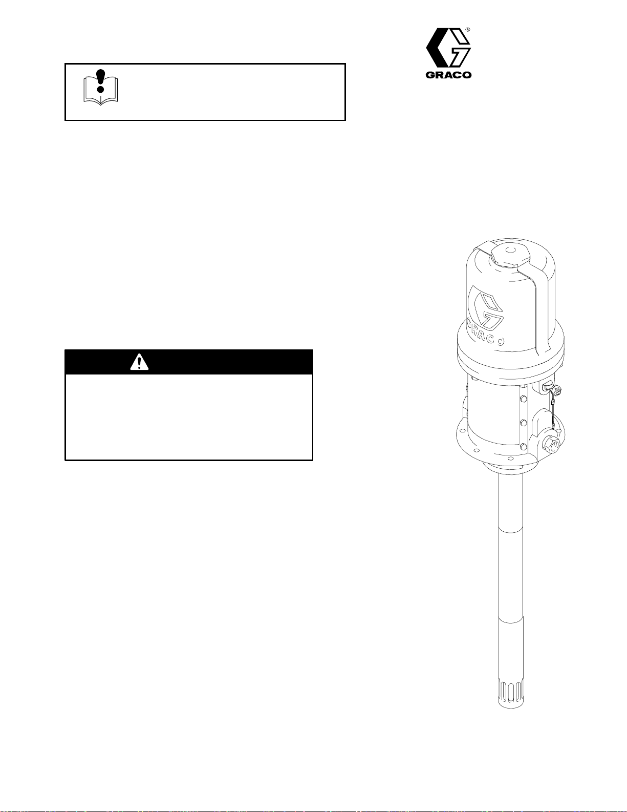
50:1 Ratio Fire-Ball Grease Pumps
FOR LUBRICATING PRODUCTS ONLY
8400 psi (58 MPa, 580 bar) Maximum Fluid Working Pressure
140 psi (0.97 MPa, 9.7 bar) Maximum Air Working Pressure
Model No. 239877, pail length
Model No. 239887, 120-pound drum length
Model No. 239888, 400-pound drum length
WARNING
This product is designed to be used only in
pumping non-corrosive and non-abrasive lubricants
and greases. Any other use can cause unsafe
operating conditions and result in component
rupture, fire, or explosion, which can cause serious
injury, including fluid injection.
Table of Contents
Warnings 2. . . . . . . . . . . . . . . . . . . . . . . . . . . . . . . . . . . . . .
Installation 5. . . . . . . . . . . . . . . . . . . . . . . . . . . . . . . . . . . . .
Operation 7. . . . . . . . . . . . . . . . . . . . . . . . . . . . . . . . . . . . .
Troubleshooting 8. . . . . . . . . . . . . . . . . . . . . . . . . . . . . . . .
Displacement Pump Service 9. . . . . . . . . . . . . . . . . . . . .
Air Motor and Throat Service 11. . . . . . . . . . . . . . . . . . . .
Parts Drawing 14. . . . . . . . . . . . . . . . . . . . . . . . . . . . . . . . .
Parts List 15. . . . . . . . . . . . . . . . . . . . . . . . . . . . . . . . . . . . .
Dimensional Drawings 17. . . . . . . . . . . . . . . . . . . . . . . . .
Mounting Hole Layout 17. . . . . . . . . . . . . . . . . . . . . . . . . .
Technical Data 17. . . . . . . . . . . . . . . . . . . . . . . . . . . . . . . .
Warranty 18. . . . . . . . . . . . . . . . . . . . . . . . . . . . . . . . . . . . .
Graco Phone Number 18. . . . . . . . . . . . . . . . . . . . . . . . . .
Model No. 239887 shown
9038A
GRACO INC. P.O. BOX 1441 MINNEAPOLIS, MN 55440–1441
COPYRIGHT 1999, GRACO INC.
Graco Inc. is registered to I.S. EN ISO 9001
Page 2

Symbols
Warning Symbol
WARNING
This symbol alerts you to the possibility of serious
injury or death if you do not follow the instructions.
WARNING
EQUIPMENT MISUSE HAZARD
Equipment misuse can cause the equipment to rupture or malfunction and result in serious injury.
This equipment is for professional use only.
Read all instruction manuals, tags, and labels before you operate this equipment.
Use the equipment only for its intended purpose. If you are not sure, call your Graco distributor.
Do not modify this equipment.
Caution Symbol
CAUTION
This symbol alerts you to the possibility of damage to
or destruction of equipment if you do not follow the
instructions.
Check equipment daily. Repair or replace worn or damaged parts immediately.
Do not exceed the maximum working pressure of the lowest rated component in your system.
This equipment has a 8400 psi (58 MPa, 580 bar) maximum working pressure at 140 psi
(0.97 MPa, 9.7 bar) maximum incoming air pressure.
Use fluids and solvents which are compatible with the equipment wetted parts. Refer to the
Technical Data section of all equipment manuals. Read the fluid and solvent manufacturer’s
warnings.
Handle hoses carefully. Do not pull on hoses to move equipment.
Route hoses away from traffic areas, sharp edges, moving parts, and hot surfaces. Do not
expose Graco hoses to temperatures above 66C (150F) or below –40C (–40F).
Do not move or lift pressurized equipment.
Comply with all applicable local, state, and national fire, electrical, and safety regulations.
2 308883
Page 3
WARNING
INJECTION HAZARD
Fluid from the dispensing valve, leaks, or ruptured components can inject fluid into your body and
cause extremely serious injury, including the need for amputation. Fluid splashed in the eyes or on
the skin can also cause serious injury.
Fluid injected into the skin might look like just a cut, but it is a serious injury. Get immediate
medical attention.
Do not point the dispensing valve at anyone or at any part of the body.
Do not put your hand or fingers over the end of the dispensing valve.
Do not stop or deflect leaks with your hand, body, glove or rag.
Use only extensions and no-drip tips which are designed for use with your dispensing valve.
Do not use a low pressure flexible nozzle with this equipment.
Follow the Pressure Relief Procedure on page 7 if the grease fitting coupler clogs and before
you clean or service this equipment.
Tighten all fluid connections before you operate this equipment.
Check the hoses, tubes, and couplings daily. Replace worn or damaged parts immediately. Do
not repair high pressure couplings; you must replace the entire hose.
TOXIC FLUID HAZARD
Hazardous fluids or toxic fumes can cause serious injury or death if splashed in the eyes or on the
skin, inhaled, or swallowed.
Know the specific hazards of the fluid you are using.
Store hazardous fluid in an approved container. Dispose of hazardous fluid according to all local,
state and national guidelines.
Always wear protective eyewear, gloves, clothing and respirator as recommended by the fluid
and solvent manufacturer.
308883
3
Page 4

WARNING
FIRE AND EXPLOSION HAZARD
Improper grounding, poor ventilation, open flames or sparks can cause a hazardous condition and
result in a fire or explosion and serious injury.
Ground the equipment and the object being dispensed to. Refer to Grounding below.
If there is any static sparking or you feel an electric shock while using this equipment, stop
dispensing immediately. Do not use the equipment until you identify and correct the problem.
Provide fresh air ventilation to avoid the buildup of flammable fumes from solvents or the fluid
being dispensed.
Keep the dispensing area free of debris, including solvent, rags, and gasoline.
Do not smoke in the dispensing area.
MOVING PARTS HAZARD
Moving parts, such as the air motor piston, can pinch or amputate your fingers.
Do not operate the pump with the air motor plates removed.
Keep clear of all moving parts when you start or operate the pump.
Before you service this equipment, follow the Pressure Relief Procedure on page 7 to prevent
the equipment from starting unexpectedly.
4 308883
Page 5
Grounding
Installation
Proper grounding is an essential part of maintaining a
safe system.
To reduce the risk of static sparking, ground the pump.
Check your local electrical code for detailed grounding
instructions for your area and type of equipment.
Ground all of this equipment:
Pump: Use a ground wire and clamp as shown
in Fig. 1.
Air and fluid hoses: Use only electrically conductive
hoses.
Air compressor: Follow the manufacturer’s
recommendations.
Fluid supply container: Follow the local code.
To maintain grounding continuity when flushing or
relieving pressure, always hold a metal part of the
valve firmly to the side of a grounded metal pail,
then trigger the valve.
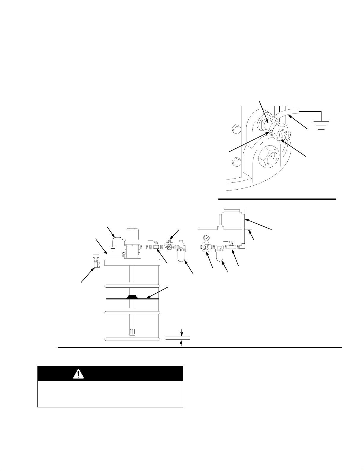
For Stationary Mountings
To ground the pump, loosen the grounding lug locknut
(W) and washer (X). Insert one end of a 12 ga (1.5
mm) minimum ground wire (Y) into the slot in lug (Z),
and tighten the locknut securely. Connect the other
end of the wire to a true earth ground. To order a
ground wire and clamp, order Part No. 222011.
Z
Y
X
Fig. 1
W
04111
B
A
J
K
Fig. 2
H
Mounting
WARNING
Mount the pump securely so that it cannot move
around during operation. Failure to do so could
result in personal injury or equipment damage.
1. Plan the mounting layout for easy operator access
to the pump air controls, sufficient room to change
drums and a secure mounting platform.
G
1/2 in.
Recommended air line
D
KEY
J
C
F
04191
2. If using a follow plate (H), remove the drum cover.
Scoop the material to the center of the drum to
make the surface concave. Place the plate on the
material. Guide the pump foot valve through the
plate.
3. Mount the pump to the drum cover or other
suitable mounting device.
4. For ease in changing drums, install a pump
elevator.
E
A Fluid dispense line
B Pump ground wire (required)
C Air regulator with gauge
D Main air supply line
E Air line filter
F Air line lubricator
G Pump runaway valve
H Follower plate
J Bleed-type Master Air Valves
K Fluid drain valve
configuration to reduce
moisture in pump
(required)
308883
5
Page 6
Installation
Air and Fluid Line and Accessories
See Fig. 2 above.
WARNING
Three accessories are required in your system: an
air shut-off valve/air bleed device, fluid drain valve,
and ground wire. These accessories help reduce
the risk of serious bodily injury, including fluid
injection, splashing in the eyes or on the skin,
injury from moving parts if you are adjusting or
repairing the pump, and explosion from static
sparking.
The air bleed device relieves air trapped
between it and the air motor after the air supply
is shut off. Trapped air can cause the air motor
to cycle unexpectedly, causing serious injury if
you are adjusting or repairing the pump. Use a
bleed-type master air valve (J). Install them
near the pump air inlet within easy reach from
the pump.
The fluid drain valve (K) assists in relieving fluid
pressure in the displacement pump, hoses, and
dispensing valve. Triggering the valve to relieve
pressure may not be sufficient.
4. Install the air regulator (C) to control pump speed
and pressure (see WARNING at left).
5. Install an air line filter (E) to remove harmful dirt
and contaminants from your compressed air
supply.
6. Install a second bleed-type master air valve (J)
upstream from all other accessories, to isolate the
accessories for servicing.
The ground wire (B) reduces the risk of static
sparking.
CAUTION
Do not hang the air accessories directly on the air
inlet. The fittings are not strong enough to support
the accessories and may cause one or more to
break. Provide a bracket on which to mount the
accessories.
NOTE: Install the air line accessories in the order
shown in Fig. 2.
1. Install a pump runaway valve (G) to shut off the air
to the pump if the pump accelerates beyond the
pre-adjusted setting. A pump that runs too fast
can be seriously damaged.
2. Install an air line lubricator (F) for automatic air
motor lubrication.
3. Install a bleed-type master air valve (J) to relieve
air trapped between the valve and the motor (see
WARNING at left). Order Part No. 107142.
6 308883
Page 7

Operation
Pressure Relief Procedure
WARNING
INJECTION HAZARD
The equipment stays pressurized until
pressure is manually relieved. To
reduce the risk of serious injury from
pressurized fluid, fluid from the valve or splashing
fluid, follow this procedure whenever you
Are instructed to relieve pressure
Stop dispensing
Check, clean or service any system equipment
Install or clean dispensing devices
1. Close the pump air regulator and the bleed-type
master air valve (required in your system).
2. Hold a metal part of the dispensing valve firmly to
a grounded metal waste container and trigger the
valve to relieve the fluid pressure.
Startup
1. If there are multiple pumps on the air line, close
the air regulators and bleed-type master air valves
to all but one pump. If there is only one pump,
close its air regulator and bleed-type master air
valve.
2. Open the master air valve from the compressor.
WARNING
COMPONENT RUPTURE HAZARD
The maximum working pressure of each
component in the system may not be the
same. To reduce the risk of
overpressurizing any component in the system, be
sure you know the maximum working pressure of
each component. Never exceed the maximum
working pressure of the lowest rated component in
the system. Overpressurizing any component can
result in rupture, fire, explosion, property damage,
and serious injury.
The pump has a rated ratio of 50:1. However, it is
capable of reaching stall pressures equal to 60
times the air input pressure. Calculate the fluid
output pressure using the air regulator reading.
Multiply the air pressure shown on the regulator
gauge by 60. For example:
140 psi air x 60 = 8400 psi fluid output
0.97 MPa air x 60 = 58.2 MPa fluid output
9.7 bar air x 60 = 582 bar fluid output
Regulate air to the pump so that no air line or fluid
line component or accessory is overpressurized.
6. Never allow the pump to run dry of the material
being pumped.
3. Open the dispensing valve into a grounded metal
waste container, making firm metal-to-metal
contact between the container and valve. Open
the bleed-type master air valve and open the pump
air regulator slowly, just until the pump is running.
When the pump is primed and all air has been
pushed out of the lines, close the dispense valve.
4. If you have more than one pump, repeat this
procedure for each pump.
NOTE: When the pump is primed, and with sufficient
air supplied, the pump starts when the dispensing
valve is opened and shuts off when it is closed.
5. Set the air pressure to each pump at the lowest
pressure needed to get the desired results.
CAUTION
A dry pump will quickly accelerate to a high speed,
possibly damaging itself. If your pump accelerates
quickly, or is running too fast, stop it immediately and
check the material supply. If the supply container is
empty and air has been pumped into the lines, prime
the pump and lines with material, or flush it and leave
it filled with a compatible solvent. Be sure to eliminate all air from the material lines.
NOTE: A pump runaway valve (G) can be installed on
the air line to automatically shut off the pump if it starts
to run too fast.
7. Read and follow the instructions supplied with
each component in your system.
8. To shut off the system, always follow the Pressure
Relief Procedure at the left.
308883
7
Page 8

Troubleshooting
WARNING
To reduce the risk of serious injury whenever you
are instructed to relieve pressure, always follow the
Pressure Relief Procedure on page 7.
fingers from pinching or amputation by moving
Relieve pressure before you check or service any
system equipment.
Problem Cause Solution
Pump fails to operate Inadequate air supply pressure or
restricted air lines
Closed or clogged pump valves Open and/or clean.
Clogged fluid line, hose, valve, or
other accessory
Damaged air motor Assess damage, and service
Exhausted fluid supply Refill and reprime or flush.
Continuous air exhaust Worn or damaged air motor
gasket or seal
Erratic pump operation Exhausted fluid supply Refill and reprime or flush
Worn pump seals Replace.
Damaged shovel tube Replace.
Damaged check seat Replace pump piston or
Pump operates, but output low on
up stroke
Pump operates, but output low on
down stroke
Pump operates, but output low on
both strokes
Grease leaking from muffler plates Worn throat seal Replace.
Worn piston seal Replace.
Damaged upper check seat Replace pump piston.
Worn fluid intake seal Replace.
Damaged lower check seat Replace shovel rod.
Inadequate air supply pressure or
restricted air lines
Closed or clogged pump valves Open and/or clean.
Exhausted fluid supply Refill fluid supply, and
Clogged fluid line, hose, valve, or
other accessory
Worn seals Replace.
parts in the air motor.
MOVING PARTS HAZARD
Never operate the pump with the
warning plate or the identification plate
removed. These plates protect your
WARNING
Increase air supply and/or
clear restriction.
Relieve pressure.
Clear obstruction.
air motor.
Assess wear or damage,
and service air motor.
shovel rod (or other damaged part).
Increase air supply and/or
clear restriction.
reprime pump.
Relieve pressure.
Clear obstruction.
8 308883
Page 9

Displacement Pump Service
Be sure you have all necessary parts on hand
before you start. If using a repair kit, use all the
parts in the kit for the best results.
Displacement Pump Repair Kit 241623 is available.
Parts included in the kit are marked with a
dagger (
) in the parts drawing and list.
WARNING
To reduce the risk of serious injury whenever you
are instructed to relieve pressure, always follow the
Pressure Relief Procedure on page 7.
1. Flush the pump.
2. Relieve the pressure before you proceed.
3. Disconnect the hoses, remove the pump from its
mounting, and clamp the air motor base (5) in a
vise.
CAUTION
To avoid damaging the shovel tube, do not use
slots in the tube to tighten or loosen tube.
7. Screw the shovel rod (58) out of the piston (52).
Remove the lower ball (56). Screw the piston out
of the extension rod (57). Remove the upper ball
(56), retaining washer (53), and seal (54).
8. Clean all the parts in a compatible solvent and
inspect them for wear or damage. Use all the
parts in the repair kit, and replace other parts as
necessary.
9. Generously lubricate all the parts with light
water-resistant grease and reassemble the pump.
NOTES:
Torque the shovel tube (67) to the pump cylinder
(59) at 45 to 55 ft-lb (61 to 75 N-m), and torque the
pump cylinder (59) to the extension tube (64) at
45 to 55 ft-lb (61 to 75 N-m).
Torque the shovel rod (58) to the piston (52) at 25
to 30 ft-lb (34 to 41 N-m), and torque piston (52) to
the extension rod (57) at 25 to 30 ft-lb (34 to 41
N-m).
10. If the ground wire was disconnected before
servicing, be sure to reconnect it before you
operate the pump.
4. Use strap wrench to screw shovel tube (67) off of
pump cylinder (59).
5. Use strap wrench to screw shovel (66) off of
shovel rod (58).
6. Use strap wrench on pump cylinder (59) to screw it
out of extension tube (64). Screw tube connector
(63) out of pump cylinder. Remove bearing (61)
and seal (62).
308883
9
Page 10

Displacement Pump Service
Using nut (63), torque the pump cylinder (59)
1
to the extension tube (64) at 45 to 55 ft-lb
(61-75 N-m).
Torque the shovel rod (58) to the piston (52)
3
at 25 to 30 ft-lb (34 to 41 N-m).
Torque the piston (52) to the extension rod
4
(57) at 25 to 30 ft-lb (34-41 N-m).
5
57
54
64
53
60
1
59
56
4
52
62
61
63
58
3
66
67
CAUTION:
Do not use slots in shovel
tube to tighten or loosen tube.
Fig. 3
10 308883
9041
B
Page 11

Air Motor and Throat Service
Before you start, be sure you have all necessary
parts on hand. Repair Kit 206728 is available for
the motor. Use all the parts in the kit for the best
results. Parts included in the kit are marked with an
asterisk (*) in the parts drawing and list.
Two accessory tools should be ordered. Use
Padded Pliers, 207579, to grip the trip rod without
damaging its surface. Use Gauge, 171818, to
ensure the proper clearance between the poppets
and seat of the transfer valve.
Disassembly
WARNING
To reduce the risk of serious injury whenever you
are instructed to relieve pressure, always follow the
Pressure Relief Procedure on page 7.
1. Flush the pump.
2. Relieve the pressure before you proceed.
3. Disconnect the hoses, remove the pump from its
mounting, and clamp the air motor base (5) in a
vise.
4. Use a strap wrench or pipe wrench on the
extension tube (64) to screw it out of the base (5).
See Fig. 4.
5. Pull the extension rod (57) down as far as it will go,
exposing the displacement rod (8).
6. Use a hammer and punch to remove the roll pin
(74) from the displacement rod (8), and unscrew
the extension rod (57) out of the displacement rod.
CAUTION
In step 7, do not damage the plated surface of the
trip rod (11). A damaged trip rod could cause
erratic air motor operation. Use the special
padded pliers, 207579, to grasp the rod.
8. Remove the six screws (21) that hold the cylinder
(17) to the base. Carefully pull the cylinder straight
up off the piston (2).
CAUTION
To avoid damaging the cylinder wall, lift the cylinder
straight up off of the piston. Never tilt the cylinder
while you are removing it.
WARNING
To reduce the risk of pinching or amputating your
fingers, always keep fingers clear of the toggle
assemblies (L). See Fig. 5.
9. Use a screwdriver to push down on the trip rod
yoke (22), and snap the toggles down. Remove
the lockwires (31) from the adjusting nuts (30) of
the transfer valves. Screw the top nuts off. Screw
the stems (1a) out of the grommets (12) and
bottom nuts. Take the valve poppets (1b) off the
stems and squeeze them firmly to check for
cracks. See Fig. 5.
10. Grip the toggle rockers (26) with a pliers.
Compress the springs (27), and swing the toggle
assembly (L) up and away from the piston lugs
(M), and remove the parts. Check to see that the
valve actuator (13) is supported by the spring clips
(14), but slides easily into them. See Fig. 5.
11. Remove the trip rod yoke (22), actuator (13), and
trip rod (11). Check the exhaust valve poppets
(16) for cracks.
NOTE: To remove cracked exhaust valve poppets
(16), stretch them out, and cut them with a sharp knife.
12. Remove one of the air motor plates (18 or 20).
Pull the piston (2) up out of the base (5). Remove
the throat packing nut (38) and throat seal (6).
7. Manually push on the displacement rod (8) to
move the air motor piston (2) up as far as it will go.
Unscrew the cylinder cap nut (29a or 29b). Pull
the nut up. Grip the trip rod (11) with padded
pliers, and screw the nut off the rod. See Fig. 4.
308883
11
Page 12

Air Motor and Throat Service
11
17
2
5
21
38
6
74
8
Torque the extension tube (64) to the base
(5) at 45 to 55 ft-lb (61 to 75 N-m).
Fig. 4
57
64
9040A
12 308883
Page 13

Reassembly
Air Motor and Throat Service
1. Clean all the parts carefully in a compatible
solvent, and inspect for wear or damage. Use all
the repair kit parts during reassembly, and replace
other parts as necessary.
2. Check the polished surfaces of the piston (2),
displacement rod (8), and cylinder (17) wall for
scratches or wear. A scored rod causes
premature throat seal wear and leaking.
3. Lubricate all parts with a light, water-resistant
grease.
4. Install the new throat seal (6), lips facing down .
Screw the packing nut (38) into the base (5).
5. Slide the displacement rod (8) down through the
throat, and lower the piston (2) into the base (5).
Be sure the o-rings (9, 10, and 24) are in place.
See Fig. 4.
6. Pull the exhaust valve poppets (16) into the valve
actuator (13), and clip off the top part shown with
dotted lines in Fig. 5.
7. Install the transfer valve grommets (12), and
reassemble the valve mechanism. Before you
install the lockwires (31) in the adjusting nuts (30),
use the special gauge, 171818, to adjust the
transfer valve so there is 0.145 in. (3.7 mm)
clearance between the poppets (1b) and the seat
when it is open. See Fig. 5. Snap the toggles (25)
to the up position.
8. Reassemble the air motor, and assemble to the
displacement pump. Torque the extension tube
(64) to to base (5) at 45 to 55 ft-lb (61 to 75 N-m).
Before you install the air motor plate, tighten the
throat packing nut (38) snugly; do not overtighten
it.
9. Before you remount the pump, connect an air
hose, and run the pump slowly, at about 40 psi
(276 kPa, 2.8 bar), to see that it operates
smoothly.
10. Reconnect the ground wire before regular
operation of the pump.
L
2
26 27 25
1
M
14
16
1
Turn wires up.
2
Push toggles (L) in and then up.
11 22
04118
2
1b
12
30
1b
31
30
13
11
14
Cutaway View
3
1a
16
30
12
30
24
0.145”
(3.7 mm)
1b
2
04119
3 Cut off tops of poppets as indicated by dotted lines.
Fig. 5
308883
13
Page 14

Air Motor Includes items 1 to 39
Parts Drawing
Model No. 239877, pail length
Model No. 239887, 120-pound drum length
Model No. 239888, 400-pound drum length
* The replacements for these parts are available
in Repair Kit 206728. Purchase the kit separately.
The replacements for these parts are available in
Repair Kit 241623. Purchase the kit separately.
27
26
23
25
13
14
15
11
16*
29a
28
22
29b
17
31*
30*
12*
30*
20
21
38
6
9*
10
5
32
60
19
18
68
3
4
7
60
59
56
52
56
62
61
63
58
24*
2
33
74
14 308883
64
1b*
1a*
57
8
53
54
66
67
8964B
Page 15

Parts List
Model No. 239877, pail length
Model No. 239887, 120-pound drum length
Model No. 239888, 400-pound drum length
Ref.
No. Part No. Description Qty.
A 238756 AIR MOTOR ASSEMBLY
239886 AIR MOTOR ASSEMBLY
1* 236079 .VALVE, poppet
1a 160896 .STEM, valve 1
1b 170708 .POPPET, valve; urethane 1
2 160614 .PISTON, air motor 1
3 104582 .W ASHER, tab 1
4 104029 .LUG, grounding 1
5 241826 .BASE 1
6 114179 .SEAL, throat 1
7 162718 .ADAPTER; 3/8 npt(m) x 1/4 npt(f) 1
8 192541 .ROD, displacement 1
9* 160625 .O-RING, buna-N 1
10 160624 .O-RING, buna-N 1
11 203965 .ROD, trip 1
12* 158367 .GROMMET, rubber, air intake 2
13 172867 .ACTUATOR, valve 1
14 172866 .CLIP, spring 2
15 102975 .SCREW, rd hd mach;
16* 170709 .POPPET, valve; urethane 2
17 160613 .CYLINDER, air motor 1
18 222499 .PLA TE, identification; with muffler 1
19 100078 .SCREW , hex head;
no. 8–32 x 0.38 in. (10 mm) long. 12
20 222501 .PLA TE, warning; with muffler 1
21 101578 .SCREW, hex head;
no. 8–32 x 0.38 in. (10 mm) long 6
22 158360 .YOKE, rod, trip 1
23 158362 .PIN, toggle 2
24* 160621 .O-RING, nitrile rubber 1
25 160623 .ARM, toggle 2
26 158364 .ROCKER, toggle 2
27 167585 .SPRING, helical compression 2
28 156698 .O-RING; buna-N 1
29a 164704 .HANDLE NUT, cylinder, cap
29b 161435 .NUT, cylinder, cap
30* 160261 .NUT, adjusting 4
31* 160618 .LOCKWIRE, transfer valve 2
32 180233 .LABEL, warning 2
33 160932 .GASKET; copper 1
38 192537 .NUT, packing 1
Model 239877
(includes items 1 to 39) 1
Models 239887 and 239888
(includes items 1 to 39) 1
(includes items 1a and 1b) 2
no. 6–32 x 0.25” (6.3 mm) 2
Model 239877 1
Models 239887 and 239888 1
Ref.
No. Part No. Description Qty.
52 196184 PISTON 1
53 196185 RETAINER, piston seal 1
54 114171 SEAL, piston 1
56 100065 BALL 2
57 192685 ROD, extension
Model 239877 1
192684 ROD, extension
Model 239887 1
192535 ROD, extension
Model 239888 1
58 192540 ROD, shovel 1
59 192538 CYLINDER, pump 1
60 192533 SEAL, gasket 2
61 192534 BEARING, shovel rod 1
62 114178 SEAL, shovel rod 1
63 192531 CONNECTOR, tube 1
64 192682 TUBE, extension
Model 239877 1
193760 TUBE, extension
Model 239887 1
193758 TUBE, extension
Model 239888 1
66 192660 SHOVEL 1
67 192539 TUBE, shovel 1
68 185220 PLATE, serial 1
74 112154 PIN, spring, straight 1
* The replacements for these parts are available in Repair
Kit 206728. Purchase the kit separately.
The replacements for these parts are available in Repair
Kit 241623. Purchase the kit separately.
Note: two accessory tools are required for air motor and
throat service: Padded Pliers, 207579 and Gauge, 171818.
308883
15
Page 16

Notes
16 308883
Page 17

Dimensional Drawings
3/8 npt(f)
air inlet
Model 239877
pail length
Overall length:
31” (788 mm)
grounding lug
1/4 npt(f)
fluid outlet
17.5”
(445 mm)
3/8 npt(f)
air inlet
Model 239887
120 lb drum size
Overall length:
38.4” (975 mm)
grounding lug
1/4 npt(f)
fluid outlet
26.7”
(678 mm)
3/8 npt(f)
air inlet
Model 239888
400 lb drum size
33.6”
(853 mm)
Overall length:
45.4” (1153 mm)
grounding lug
1/4 npt(f)
fluid outlet
9039A
Mounting Hole
Layout
2-Hole Mounting
Pattern
161023 gasket
two or four
0.265” (7 mm)
dia. holes on 5”
(127 mm) bolt circle
3” (76.2 mm) dia.
4-Hole Mounting
Pattern
04127
Technical Data
Maximum working pressure 8400 . . . . . . . . . . . . . . . . . .
(58 MPa, 580 bar)
Fluid pressure ratio 50:1. . . . . . . . . . . . . . . . . . . . . . . . . .
Air operating range 30 to 140 psi. . . . . . . . . . . . . . . . . . .
(0.3 to 0.97 MPa, 3 to 9.7 bar)
Air consumption 22.8 cfm (0.638 m/min). . . . . . . . . . . .
at 0.25 gpm (0.95 liter/min),
at 100 psi (0.7 MPa, 7 bar)
Gallons (liters) per pump cycle 0.003 (0.0109). . . . . .
Maximum recommended
pump speed 76 cycles/min. . . . . . . . . . . . . . . . . . . . . . . .
0.22 gpm (0.82 liter/min)
Wetted parts steel, brass, aluminum,. . . . . . . . . . . . . . .
Delrin, nitrile rubber, polyurethane
Sound pressure level
(measured at 1 meter from unit) 77.8 dB(A). . . . . . . . .
Sound power level
(tested in accordance with ISO 9614–2) 85.6 dB(A). .
Approximate weight 22 lb (10 Kg). . . . . . . . . . . . . . . . . . .
Delrin
Loctite is a registered trademark of the Loctite Corp.
308883
17
Page 18

Warranty
Graco warrants all equipment manufactured by Graco and bearing its name to be free from defects in material and workmanship on the
date of sale by an authorized Graco distributor to the original purchaser for use. With the exception of any special, extended, or limited
warranty published by Graco, Graco will, for a period of twelve months from the date of sale, repair or replace any part of the equipment
determined by Graco to be defective. This warranty applies only when the equipment is installed, operated and maintained in accordance with Graco’s written recommendations.
This warranty does not cover, and Graco shall not be liable for general wear and tear, or any malfunction, damage or wear caused by
faulty installation, misapplication, abrasion, corrosion, inadequate or improper maintenance, negligence, accident, tampering, or substitution of non-Graco component parts. Nor shall Graco be liable for malfunction, damage or wear caused by the incompatibility of
Graco equipment with structures, accessories, equipment or materials not supplied by Graco, or the improper design, manufacture,
installation, operation or maintenance of structures, accessories, equipment or materials not supplied by Graco.
This warranty is conditioned upon the prepaid return of the equipment claimed to be defective to an authorized Graco distributor for
verification of the claimed defect. If the claimed defect is verified, Graco will repair or replace free of charge any defective parts. The
equipment will be returned to the original purchaser transportation prepaid. If inspection of the equipment does not disclose any defect
in material or workmanship, repairs will be made at a reasonable charge, which charges may include the costs of parts, labor, and
transportation.
THIS WARRANTY IS EXCLUSIVE, AND IS IN LIEU OF ANY OTHER WARRANTIES, EXPRESS OR IMPLIED, INCLUDING BUT
NOT LIMITED TO WARRANTY OF MERCHANTABILITY OR WARRANTY OF FITNESS FOR A PARTICULAR PURPOSE.
Graco’s sole obligation and buyer’s sole remedy for any breach of warranty shall be as set forth above. The buyer agrees that no other
remedy (including, but not limited to, incidental or consequential damages for lost profits, lost sales, injury to person or property, or any
other incidental or consequential loss) shall be available. Any action for breach of warranty must be brought within two (2) years of the
date of sale.
Graco makes no warranty, and disclaims all implied warranties of merchantability and fitness for a particular purpose in connection
with accessories, equipment, materials or components sold but not manufactured by Graco. These items sold, but not manufactured
by Graco (such as electric motors, switches, hose, etc.), are subject to the warranty, if any, of their manufacturer. Graco will provide
purchaser with reasonable assistance in making any claim for breach of these warranties.
In no event will Graco be liable for indirect, incidental, special or consequential damages resulting from Graco supplying equipment
hereunder, or the furnishing, performance, or use of any products or other goods sold hereto, whether due to a breach of contract,
breach of warranty, the negligence of Graco, or otherwise.
FOR GRACO CANADA CUSTOMERS
The parties acknowledge that they have required that the present document, as well as all documents, notices and legal proceedings
entered into, given or instituted pursuant hereto or relating directly or indirectly hereto, be drawn up in English. Les parties reconnaissent avoir convenu que la rédaction du présente document sera en Anglais, ainsi que tous documents, avis et procédures judiciaires
exécutés, donnés ou intentés à la suite de ou en rapport, directement ou indirectement, avec les procedures concernées.
Extended Product Warranty
Graco warrants all Fire–Ball Grease Pumps to be free from defects in material and workmanship for a period of thirty years from date
installed in service by the original purchaser. Normal wear of items such as packings or valve seats are not considered to be defects in
material and workmanship.
One year Graco will provide parts and labor.
Two through thirty years Graco will replace defective parts only.
Graco Phone Number
TO PLACE AN ORDER, contact your Graco distributor, or call this number to identify the distributor closest to you:
1–800–533–9655 Toll Free
All written and visual data contained in this document reflect the latest product information available at the time of publication.
Graco reserves the right to make changes at any time without notice.
18 308883
Foreign Offices: Belgium, Korea, Hong Kong, Japan
Sales Offices: Minneapolis, Detroit
GRACO INC. P.O. BOX 1441 MINNEAPOLIS, MN 55440–1441
www.graco.com
PRINTED IN USA 308883 April 1999, Revised February 2000
 Loading...