

Page 1

Instructions - Parts List
™
IM5
Inline
308687L
Electronic Meter
For use with petroleum-based and synthetic oil, antifreeze, and windshield washer fluid
only.
Model: 239824
500 psi (3.4 MPa, 34 bar) Maximum Working Pressure
5 gpm (19 lpm) Maximum Flow Rate
Important Safety Instructions
Read all warnings and instructions in this manual.
Save these instructions.
EN
Page 2

Warnings
Warnings
The following warnings are for the setup, use, grounding, maintenance, and repair of this equipment. The exclamation point symbol alerts you to a general warning and the hazard symbols refer to procedure-specific risks. When
these symbols appear in the body of this manual or on warning labels, refer back to these Warnings. Product-specific hazard symbols and warnings not covered in this section may appear throughout the body of this manual
where applicable.
+
SKIN INJECTION HAZARD
High-pressure fluid from dispensing device, hose leaks, or ruptured components will pierce skin. This
may look like just a cut, but it is a serious injury that can result in amputation. Get immediate surgi-
cal treatment.
• Do not point dispensing device at anyone or at any part of the body.
• Do not put your hand over the fluid outlet.
• Do not stop or deflect leaks with your hand, body, glove, or rag.
• Follow the Pressure Relief Procedure when you stop dispensing and before cleaning, checking,
or servicing equipment.
• Tighten all fluid connections before operating the equipment.
• Check hoses and couplings daily. Replace worn or damaged parts immediately.
FIRE AND EXPLOSION HAZARD
When flammable fluids are present in the work area, such as gasoline and windshield wiper fluid, be
aware that flammable fumes can ignite or explode. To help prevent fire and explosion:
• Use equipment only in well ventilated area.
• Eliminate all ignition sources, such as cigarettes and portable electric lamps.
• Ground all equipment in the work area.
• Keep work area free of debris, including rags and spilled or open containers of solvent and gasoline.
• Do not plug or unplug power cords or turn lights on or off when flammable fumes are present.
• Use only grounded hoses.
• Stop operation immediately if static sparking occurs or you feel a shock. Do not use equipment
until you identify and correct the problem.
• Keep a working fire extinguisher in the work area.
PRESSURIZED EQUIPMENT HAZARD
Over-pressurization can result in equipment rupture and serious injury.
• Do not exceed the maximum air input pressure.
• Fill slowly to avoid over pressurizing reservoir.
• Use tubing, hoses and other components with pressure ratings equal to or higher than the pump
rating.
2 308687L
Page 3

Warnings
EQUIPMENT MISUSE HAZARD
Misuse can cause death or serious injury.
• Do not operate the unit when fatigued or under the influence of drugs or alcohol.
• Do not exceed the maximum working pressure or temperature rating of the lowest rated system
component. See Technical Data in all equipment manuals.
• Use fluids and solvents that are compatible with equipment wetted parts. See Technical Data in
all equipment manuals. Read fluid and solvent manufacturer’s warnings. For complete information
about your material, request SDS from distributor or retailer.
• Turn off all equipment and follow the Pressure Relief Procedure when equipment is not in use.
• Check equipment daily. Repair or replace worn or damaged parts immediately with genuine manufacturer’s replacement parts only.
• Do not alter or modify equipment. Alterations or modifications may void agency approvals and create safety hazards.
• Make sure all equipment is rated and approved for the environment in which you are using it.
• Use equipment only for its intended purpose. Call your distributor for information.
• Route hoses and cables away from traffic areas, sharp edges, moving parts, and hot surfaces.
• Do not kink or over bend hoses or use hoses to pull equipment.
• Keep children and animals away from work area.
• Comply with all applicable safety regulations.
PERSONAL PROTECTIVE EQUIPMENT
Wear appropriate protective equipment when in the work area to help prevent serious injury, including eye injury, hearing loss, inhalation of toxic fumes, and burns. This protective equipment includes
but is not limited to:
• Protective eyewear, and hearing protection.
• Respirators, protective clothing, and gloves as recommended by the fluid and solvent manufacturer.
308687L 3
Page 4

Installation
Installation
The meters must be installed in-line as part of a dispense system as shown in Fig. 1. The typical installation shown
is only a guide for selecting and installing an in-line meter; it is not an actual system design. Contact your Graco distributor for assistance in designing a system to suit your needs.
NOTICE
Do not use PTFE tape on threaded connections to
the meter. Such use could contribute to over-tight-
All electrical wiring must be done by a qualified electrician and comply with all local codes and regulations.
Do not use the IM5 In-line Electronic Meter in systems where the operating pressure exceeds the maximum pressure of the meter or any other component
in the system.
ening of the parts and cause the meter housing to
crack. Standard pipe thread compound is recommended.
FIG. 1
Key:
A Shut-off valve
B Thermal relief valve (required; Part No. 235998) Install
downstream from the pump
C In-line filter
D In-line electronic meter
4 308687L
Page 5

Grounding
The equipment must be grounded to reduce the risk
of static sparking. Static sparking can cause fumes
to ignite or explode. Grounding provides an escape
wire for the electric current.
Pump: follow the manufacturer’s recommendations.
Air and fluid hoses: use only grounded hoses.
Air compressor: follow manufacturer’s recommenda-
tions.
Fluid supply container: follow local code.
To maintain grounding continuity when flushing or
relieving pressure: hold metal part of the dispense
valve firmly to the side of a grounded metal pail, then
trigger the valve.
Installation
Factory Settings
The meter is factory calibrated for 10W-30 oil, and the
default unit of measurement is quarts. For other fluids
and different units of measurement, see Changing the
Measurement Units and Calibration Factor on page 8.
308687L 5
Page 6

Operation
Operation
Sleep Mode
The meter automatically shuts down the display after
one minute of non-use.
Activation Mode
There are two ways to activate the display:
• Press any button on the keypad to wake up the dig-
ital display. The amount displayed is the value
stored when the meter went into sleep mode.
FIG. 2: Example of Total for Last Dispense Cycle
• Dispense fluid through the meter to wake up the
digital display. Dispensing fluid through the meter
causes the meter to count up from the last dis-
played value. See Fig. 2.
Function of TOTAL
Press and hold the TOTAL key to see the accumulated
total of fluid dispensed through the meter.
The accumulated total is shown in gallons when the unit
of measurement is set in gallons, quarts, or pints. The
accumulated total is shown in liters when the measurement is set in liters. The meter accumulates a running
total of up to 99,999 gallons (or liters) dispensed before
returning to zero. See Fig. 3.
Function of RESET
Press and hold the RESET key to clear the digital display after each dispense cycle.
NOTE: Always press the RESET key to clear the digital
display before each new dispense cycle.
FIG. 3: Example of Accumulated Total
FIG. 4: Example of Measurement Units
For Maximum Dispensing Accuracy
Set the meter to dispense in pints or quarts when dispensing 1 gallon (3.8 liters) or less.
Measurement Units
Fig. 4 shows the various measurement units as they
appear on the display.
6 308687L
Page 7

Operation
Changing the Measurement Units and
Calibration Factor
NOTE: A one liter Weights and Measures approved
container is required for calibration.
This meter is factory calibrated to dispense 10W-30
motor oil at 70_ F (21_ C) at 2.0 gpm (7.6 lpm) and is
acceptably accurate for most common fluids over a
typical temperature range. If you will use the meter to
dispense antifreeze or other approved fluids, you may
have to recalibrate it for greater accuracy.
1. Press and hold both the TOTAL and RESET but-
tons for four seconds.
The numbers on the display turn off, and the L (for
liters) and CAL (for calibration) icons turn on.
2. Set the units of measurement by repeatedly pressing the RESET button until the correct unit of measurement is displayed. See the list below:
GAL = gallons
QTS = quarts
PTS = pints
L = liters
number may vary slightly due to temperature or
flow rate.
Calibration
Fluid
oil (10W-30) 389
gear lube 389
automatic transmission fluid 389
antifreeze 367
windshield washer solvent 341
Calibration factors at 70°F (21°C) at 2.0 gpm (7.6 lpm)
Number
3. Press the TOTAL button to go to the CALIBRA-
TION menu.
NOTE: If you do not want to change the calibration
factor, press the TOTAL button again to use the
existing calibration factor and to resume normal
operation. To change the calibration factor, do
steps 4 and 5.
4. Dispense exactly one liter of fluid into a calibrated
1-liter container. For proper calibration, you must
dispense exactly 1 liter according to the markings
on the container.
NOTE: If you dispense more than 1 liter, press the
TOTAL button to exit the CALIBRATION menu.
Pressing the TOTAL button at this point does not
save the new calibration factor. You must complete
steps 1 to 5 change the calibration factor.
5. Press the RESET button to store the new calibration factor and resume normal operation.
NOTE: The number on the display is the calibration
factor number. It must be in the range of 311 to
466. The following table lists approximate calibration factors for different fluids. Your calibration
308687L 7
Page 8
Service
Service
NOTICE
To avoid damaging the electronic components of the
control:
• Do not remove the black cover over the electronic
area when you replace the battery. There are no
user-replaceable components under this cover.
• Do not lay anything on the electronics.
• Do not twist or force parts. Align parts properly as
instructed.
To avoid malfunction or high-pressure fluid spray, do
not remove the metal cover of the metering unit.
There are no user-serviceable part inside.
Pressure Relief Procedure
Follow the Pressure Relief Procedure whenever
you see this symbol.
This equipment stays pressurized until pressure is
manually relieved. To help prevent serious injury from
pressurized fluid, such as skin injection, splashing
fluid and moving parts, follow the Pressure Relief
Procedure when you stop dispensing and before
cleaning, checking, or servicing the equipment.
1. Turn off power supply to the pump.
2. Trigger the dispense valve into a waste container to
relieve pressure.
3. Open any bleed-type master air valves and fluid
drain valves in the system.
4. Leave the drain valve open until you are ready to
pressurize the system.
NOTE: Before you check or repair the meter, be sure all
other valves, controls and the pump are operating correctly.
8 308687L
Page 9

Service
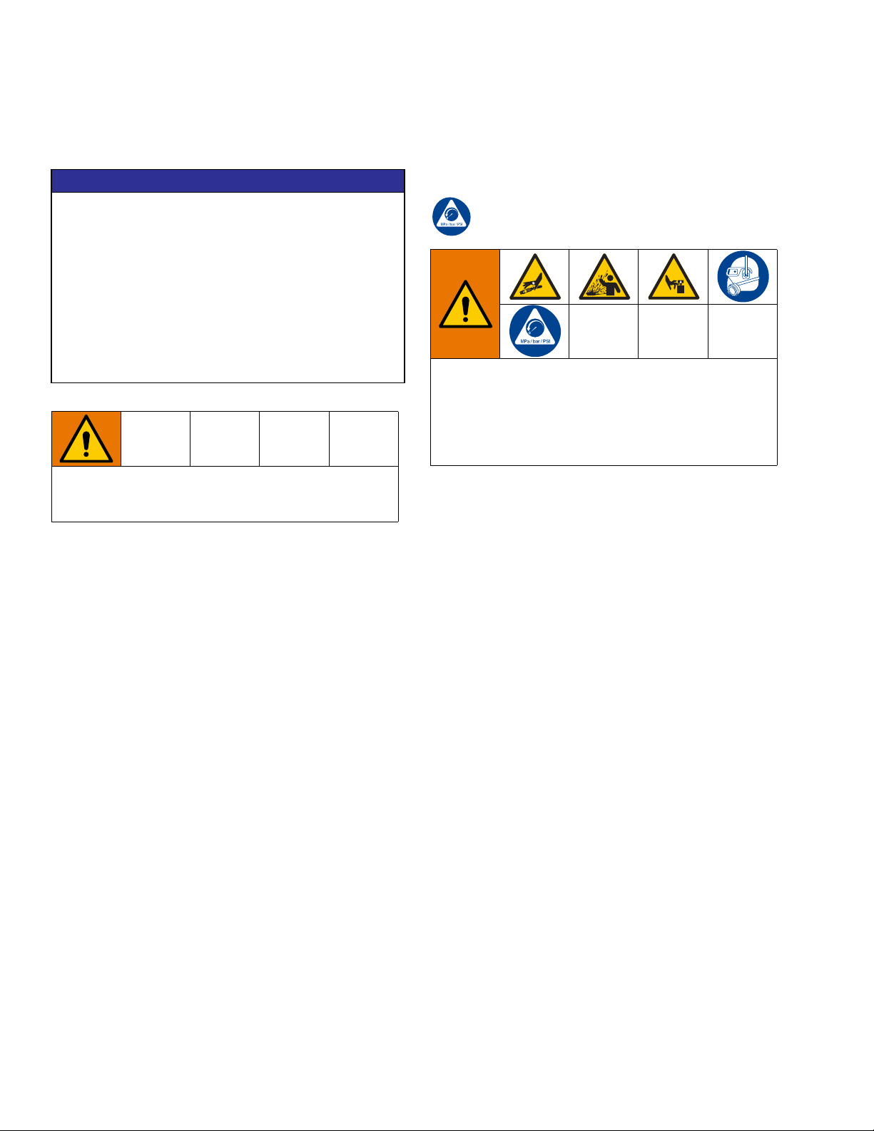
Battery Replacement Procedure
(FIG. 5)
1. Relieve Pressure, (see procedure in previous sec-
tion).
5. Install the electronic control to the metering unit (4),
aligning the longer screws boss on the meter housing with the counter bore in the plastic housing.
6. Install the four screws (3) holding the electronic
control (1) to the metering unit (4) together. Torque
the screws to 15-20 in-lb (1.7 to 2.3 N•m) or until
no gap exists between the electronic control and
the metering unit.
NOTICE
Closing the gap between the electronic control and
the metering unit is very important; it ensures that
no moisture can enter the electronics.
Electronic Control Replacement
Procedure (FIG. 6)
FIG. 5
2. Remove the four screws (3) holding the electronic
control (1) and metering unit (4) together.
3. Remove the battery.
4. Install the new battery.
NOTE: See Technical Data, page 13 for recommended
batteries.
NOTICE
To avoid pinching the battery wires, install the battery as shown in FIG. 5. The battery wire should
extend to the far side of the battery compartment.
1. Relieve Pressure, (see procedure in previous sec-
tion).
FIG. 6
2. Remove the four screws (3) holding the electronic
control (1) and metering unit (4) together.
3. Remove the battery. (See Battery Replacement
Procedure in the previous section).
308687L 9
Page 10

Service
4. Remove all gasket material from the metering unit
(4).
5. Assemble adhesive side of new gasket (2) to metering unit (4).
6. Replace battery (see Battery Replacement Procedure, page 9).
NOTICE
To avoid pinching the battery wires, install the battery as shown in FIG. 5. The battery wire should
extend to the far side of the battery compartment.
7. Install the electronic control to the metering unit (4),
aligning the longer screws boss on the meter housing with the counter bore in the plastic housing.
8. Install the four screws (3) holding the electronic
control (1) to the metering unit (4) together. Torque
the screws to 15-20 in-lb (1.7 to 2.3 N•m) or until
no gap exists between the electronic control and
the metering unit.
NOTICE
Closing the gap between the electronic control and
the metering unit is very important; it ensures that
no moisture can enter the electronics.
10 308687L
Page 11

Troubleshooting
Troubleshooting
Problem Cause Solution
Battery icon is shown on the display Battery is low Replace the battery. See Battery
Replacement Procedure, page 9
and Technical Data, page 13 for
recommended battery.
Digital display does not activate Battery is low Replace the battery. See Battery
Replacement Procedure, page 9
and Technical Data, page 13 for
recommended battery.
Electronic control is malfunctioning Replace electronic control. See
Electronic Control Replacement
Procedure, page 9.
There is no fluid flow Metering unit is malfunctioning Replace the meter.
Strainer (if used) is clogged Remove and clean or replace
strainer using Strainer Kit 239876.
See Accessories, page 12.
Pump is not turned on. Turn on pump.
308687L 11
Page 12
Parts
Parts
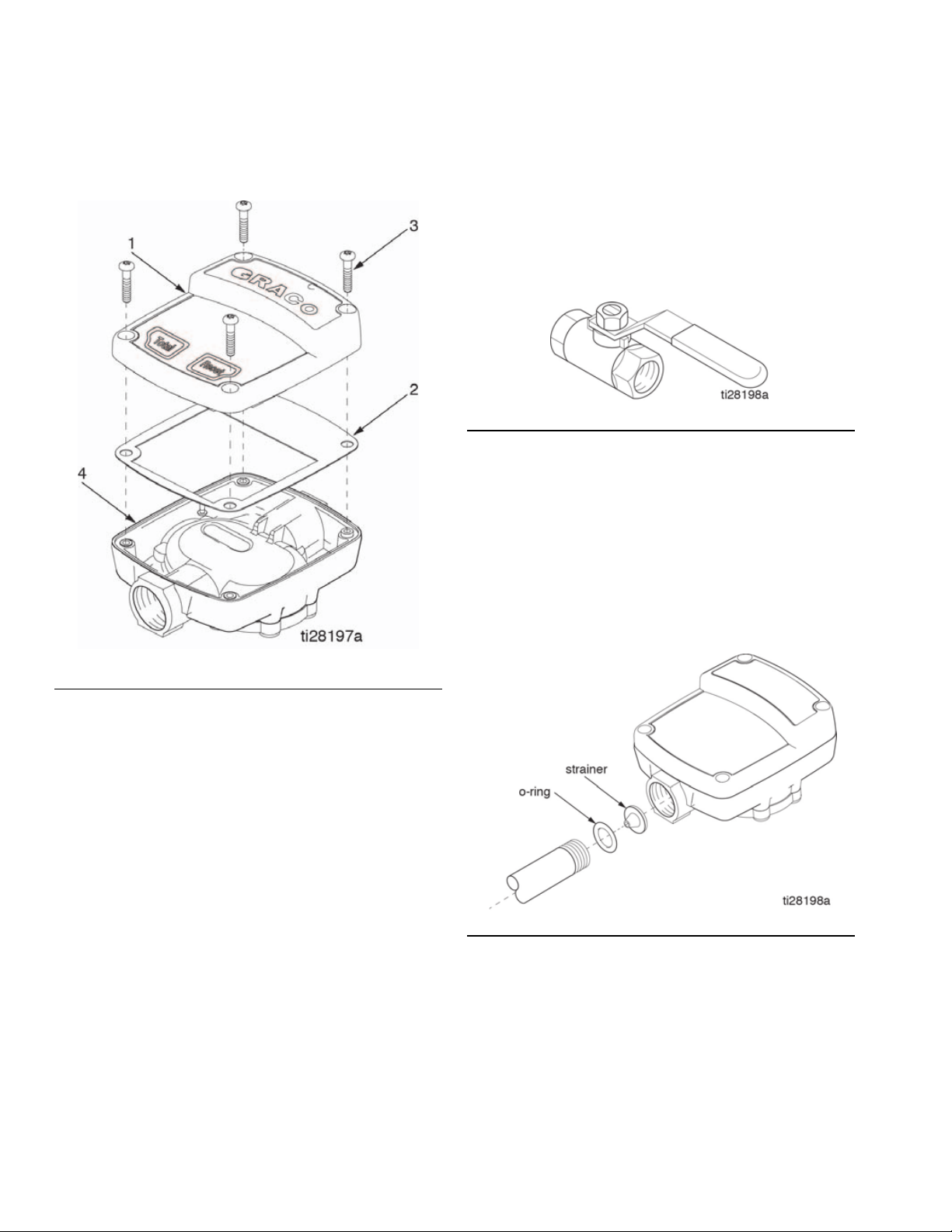
Accessories
Shutoff Valve: 108458
Install upstream from the meter. Shuts off fluid supply
from the pump.1/2-14 npt(f) both ends.
FIG. 8
Strainer Kit: 239876
Includes strainer and o-ring.
Install the strainer before the meter or before the valve
on the meter/valve combination.
Install the o-ring after the strainer to hold the strainer in
place. See FIG. 9.
FIG. 7
Part No./Description
Qty
Ref. Part Description
1 245598* CONTROL, electronic 1
2 113930 GASKET 1
3 113941 SCREW 4
4 UNIT, metering (cannot be sold
separately)
*Screws (3) and Gasket (2) are included with Control (1)
.
1
FIG. 9
Thermal Relief Kit: 235998
1/2 - 14 npt(m) x 1/2-14 npt(f).
Install downstream from the pump.
12 308687L
Page 13

Technical Data
IM5 Inline Electronic Meter
US Metric
Flow range 0.5 to 5 gpm 1.9 to 19 lpm
Maximum working pressure 500 psi 3.4 MPa, 34 bar
Minimum working pressure 5 psi 34 kPa, 0.3 bar
Weight
Weight
Units of Measurement
Factory-setting quarts
Accuracy +/- 0.5 percent
Measured at 2.5 gpm (9.5 lpm), at 70°F (21°C), with 10-weight oil and 1 gallon dispensed. May require
calibration; out-of-box accuracy is +/- 1.25 percent.
Repeatability +/- 0.15 percent
Measured at 2.5 gpm (9.5 lpm), at 70°F (21°C), with 10-weight oil and 1 gallon dispensed.
Inlet / Outlet: Meter can be installed with flow
in either direction
Temperature
Operating temperature range -4°F to 122°F -20°C to 50°C
Storage temperature range -13°F to 122°F -25°C to 50°C
Materials of Construction
Wetted parts nickel, zinc, LCP, nitrile rubber
Battery Information
Battery
Duracell® is a registered trademark of Duracell Inc.
1.8 lbs
1/2 npt
standard 9V alkaline: Duracell® MN1604, Duracell PC1604,
Eveready® EN22, Eveready 522
0.82 kg
Technical Data
Eveready® is a registered trademark of the Eveready Battery Co., Inc.
308687L 13
Page 14

Graco Standard Warranty
Graco warrants all equipment referenced in this document which is manufactured by Graco and bearing its name to be free from defects in
material and workmanship on the date of sale to the original purchaser for use. With the exception of any special, extended, or limited warranty
published by Graco, Graco will, for a period of twelve months from the date of sale, repair or replace any part of the equipment determined by
Graco to be defective. This warranty applies only when the equipment is installed, operated and maintained in accordance with Graco’s written
recommendations.
This warranty does not cover, and Graco shall not be liable for general wear and tear, or any malfunction, damage or wear caused by faulty
installation, misapplication, abrasion, corrosion, inadequate or improper maintenance, negligence, accident, tampering, or substitution of
non-Graco component parts. Nor shall Graco be liable for malfunction, damage or wear caused by the incompatibility of Graco equipment with
structures, accessories, equipment or materials not supplied by Graco, or the improper design, manufacture, installation, operation or
maintenance of structures, accessories, equipment or materials not supplied by Graco.
This warranty is conditioned upon the prepaid return of the equipment claimed to be defective to an authorized Graco distributor for verification
of the claimed defect. If the claimed defect is verified, Graco will repair or replace free of charge any defective parts. The equipment will be
returned to the original purchaser transportation prepaid. If inspection of the equipment does not disclose any defect in material or
workmanship, repairs will be made at a reasonable charge, which charges may include the costs of parts, labor, and transportation.
THIS WARRANTY IS EXCLUSIVE, AND IS IN LIEU OF ANY OTHER WARRANTIES, EXPRESS OR IMPLIED, INCLUDING BUT NOT
LIMITED TO WARRANTY OF MERCHANTABILITY OR WARRANTY OF FITNESS FOR A PARTICULAR PURPOSE.
Graco’s sole obligation and buyer’s sole remedy for any breach of warranty shall be as set forth above. The buyer agrees that no other remedy
(including, but not limited to, incidental or consequential damages for lost profits, lost sales, injury to person or property, or any other incidental
or consequential loss) shall be available. Any action for breach of warranty must be brought within two (2) years of the date of sale.
GRACO MAKES NO WARRANTY, AND DISCLAIMS ALL IMPLIED WARRANTIES OF MERCHANTABILITY AND FITNESS FOR A
PARTICULAR PURPOSE, IN CONNECTION WITH ACCESSORIES, EQUIPMENT, MATERIALS OR COMPONENTS SOLD BUT NOT
MANUFACTURED BY GRACO. These items sold, but not manufactured by Graco (such as electric motors, switches, hose, etc.), are subject to
the warranty, if any, of their manufacturer. Graco will provide purchaser with reasonable assistance in making any claim for breach of these
warranties.
In no event will Graco be liable for indirect, incidental, special or consequential damages resulting from Graco supplying equipment hereunder,
or the furnishing, performance, or use of any products or other goods sold hereto, whether due to a breach of contract, breach of warranty, the
negligence of Graco, or otherwise.
FOR GRACO CANADA CUSTOMERS
The Parties acknowledge that they have required that the present document, as well as all documents, notices and legal proceedings entered
into, given or instituted pursuant hereto or relating directly or indirectly hereto, be drawn up in English. Les parties reconnaissent avoir convenu
que la rédaction du présente document sera en Anglais, ainsi que tous documents, avis et procédures judiciaires exécutés, donnés ou intentés,
à la suite de ou en rapport, directement ou indirectement, avec les procédures concernées.
Graco Information
For the latest information about Graco products, visit www.graco.com.
For patent information, see www.graco.com/patents.
TO PLACE AN ORDER, contact your Graco distributor or call to identify the nearest distributor.
Phone: 612-623-6928 or Toll Free: 1-800-533-9655, Fax: 612-378-3590
All written and visual data contained in this document reflects the latest product information available at the time of publication.
GRACO INC. AND SUBSIDIARIES • P.O. BOX 1441 • MINNEAPOLIS MN 55440-1441 • USA
Copyright 2001, Graco Inc. All Graco manufacturing locations are registered to ISO 9001.
Graco reserves the right to make changes at any time without notice.
Original instructions. This manual contains English. MM308687
Graco Headquarters: Minneapolis
International Offices: Belgium, China, Japan, Korea
www.graco.com
February, 2021
 Loading...