

Page 1

INSTRUCTIONS-PARTS
LIST
308–781
This
manual contains important
warnings and information.
READ AND KEEP FOR REFERENCE.
INSTRUCTIONS
Husky
715 T
exture Pump
First
choice when
quality counts.
100 psi (0.7 MPa, 7 bar) Maximum Air and Fluid Working Pressure
Model
U.S.
Other U.S. and Foreign Patents Pending
Warnings 2.
Operation 4
Maintenance 5
Troubleshooting 6
Service
Service
Service
Parts
Parts
Technical
Graco Warranty 20.
Graco
239–421, Series A
Patent Nos. 4,789,131 and 4,867,653
Table
. . . . . . . . . . . . . . . . . . . . . . . . . . . . . . . . . . . . .
. . . . . . . . . . . . . . . . . . . . . . . . . . . . . . . . . . . . .
– Air V
– Duckbill V
– Diaphragm
List
. . . . . . . . . . . . . . . . . . . . . . . . . . . . . . . . . . . .
Drawing
Data
Phone Number
of Contents
. . . . . . . . . . . . . . . . . . . . . . . . . . . . . . . . . . .
. . . . . . . . . . . . . . . . . . . . . . . . . . . . . . . .
alve 7.
. . . . . . . . . . . . . . . . . . . . . . . . . . . .
alves 12.
. . . . . . . . . . . . . . . . . . . . . .
. . . . . . . . . . . . . . . . . . . . . . . . .
. . . . . . . . . . . . . . . . . . . . . . . . . . . . . . .
. . . . . . . . . . . . . . . . . . . . . . . . . . . . . . .
. . . . . . . . . . . . . . . . . . . . . . . . . . . . . .
. . . . . . . . . . . . . . . . . . . . . . . . .
13.
16.
17.
19.
20.
Rev. A
GRACO INC. P.O. BOX 1441
MINNEAPOLIS, MN
COPYRIGHT
Graco
Inc. is registered to I.S. EN ISO 9001
1997, GRACO INC.
7323A
55440–1441
Page 2
Symbols
Warning Symbol
WARNING
This
symbol alerts you to the possibility of serious
injury or death if you do not follow the instructions.
WARNING
EQUIPMENT MISUSE HAZARD
INSTRUCTIONS
Equipment
D
This equipment is for professional use only
D
Read all instruction manuals, tags, and labels before operating the equipment.
D
Use the equipment only for its intended purpose. If you are not sure, call your Graco distributor
D
Do not expose the system to rain. Always store the system indoors.
D
Do not alter or modify this equipment.
misuse can cause the equipment to rupture or malfunction and result in serious injury
Caution Symbol
CAUTION
This
symbol alerts you to the possibility of damage to
or destruction of equipment if you do not follow the
instructions.
.
.
.
D
Check equipment daily
D
Do not exceed the maximum working pressure of the lowest rated component in your system. This
equipment has a
7 bar) maximum air pressure.
D
The system is for use only with water-based simulated acoustic and wall texture materials.
Use fluids and solvents which are compatible with the equipment wetted parts. Refer to the
nical Data
D
Do not use hoses to pull equipment.
D
Route hoses away from traffic areas, sharp edges, moving parts, and hot surfaces. Do not expose
Graco hoses to temperatures above 82_C (180_F) or below –40_C (–40
D
Do not lift pressurized equipment.
D
Comply with all applicable local, state, and national fire, electrical, and safety regulations.
section of all equipment manuals. Read the fluid and solvent manufacturer’s warnings.
. Repair or replace worn or damaged parts immediately
100 psi (0.7 MPa, 7 bar) maximum working pressure at 100 psi (0.7 MPa,
.
_F).
Tech-
Page 3
TOXIC FLUID HAZARD
WARNING
Hazardous
inhaled, or swallowed.
Know the specific hazards of the fluid you are using.
Store hazardous fluid in an approved container
state and national guidelines.
Always wear protective eyewear
solvent manufacturer
Pipe and dispose of the exhaust air safely
the diaphragm fails, the fluid is exhausted along with the air
fluid or toxic fumes can cause serious injury or death if splashed in the eyes or on the skin,
. Dispose of hazardous fluid according to all local,
, gloves, clothing and respirator as recommended by the fluid and
.
, away from people, animals, and food handling areas. If
.
FIRE AND EXPLOSION HAZARD
Improper
result in a fire or explosion and serious injury
grounding, poor ventilation, open flames or sparks can cause a hazardous condition and
.
Ground the equipment. See the
If there is any static sparking or you feel an electric shock while using this equipment,
ing immediately. Do not use the equipment until you identify and correct the problem.
Grounding
section in instruction manual 308–718.237683
stop pump-
Provide fresh air ventilation to avoid the buildup of flammable fumes from solvents or the fluid
being pumped.
Keep the work area free of debris, including solvent, rags, and gasoline.
Electrically disconnect all equipment in the work area.
Extinguish all open flames or pilot lights in the work area.
Do not smoke in the work area.
Do not turn on or of
Do not operate a gasoline engine in the work area.
f any light switch in the work area while operating or if fumes are present.
Page 4

Operation
See your system manual for operating instructions.
4 308-781
Page 5
Maintenance
WARNING
PRESSURIZED EQUIPMENT HAZARD
The equipment stays pressurized until pressure is
manually relieved. To reduce the risk of serious
injury from pressurized fluid, accidental spray from
the gun or splashing fluid, follow this procedure
whenever you
Are instructed to relieve the pressure
Stop pumping
Check or service any system equipment
Install or clean the spray nozzle
Pressure Relief Procedure
1. Shut
2. T
3.
4.
Daily checks
of
f the system.
rigger the gun.
Open the gun air valve, if so equipped.
Disconnect the power source.
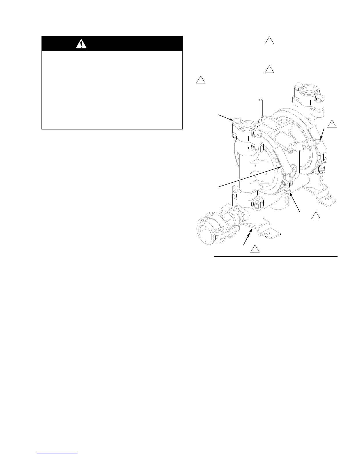
Key
A
Air inlet
110
Clamp nuts
109 Clamps
Add
two drops of machine
oil into air inlet every 50
hours.
59
109
Apply thread lubricant to
bolts, and torque the nuts
(1
10) to 75 to 85 in-lb
(8.5 to 9.6 N.m).
Torque
to 3 to 6 ft-lb
(4 to 8 N-m).
A
Before
each use, check all hoses for wear or damage
and replace as necessary
are tight and leak-free.
. Be sure hose connections
Pump lubrication
After
every 50 hours of fluid pumped, or every month,
remove the quick-disconnect hose from the pump air
inlet (A). Add two drops of machine oil into the air inlet.
Refer to Fig. 1.
Tighten pump’s threaded
connections every six months
Remove
and tighten all threaded connections.
When tightening the clamps (109), apply thread
lubricant to the bolts, and
(1
T
orque the manifold bolts (105) and the adaptor bolts
(59) to 3 to 6 ft-lb (4 to 8 N-m).
the pump from the cart and thoroughly check
be sure
10) to 75 to 85 in-lb (8.5 to 9.6 N.m). See Fig. 1.
to torque the nuts
Fig.
1
105
110
7324A
5308-781
Page 6
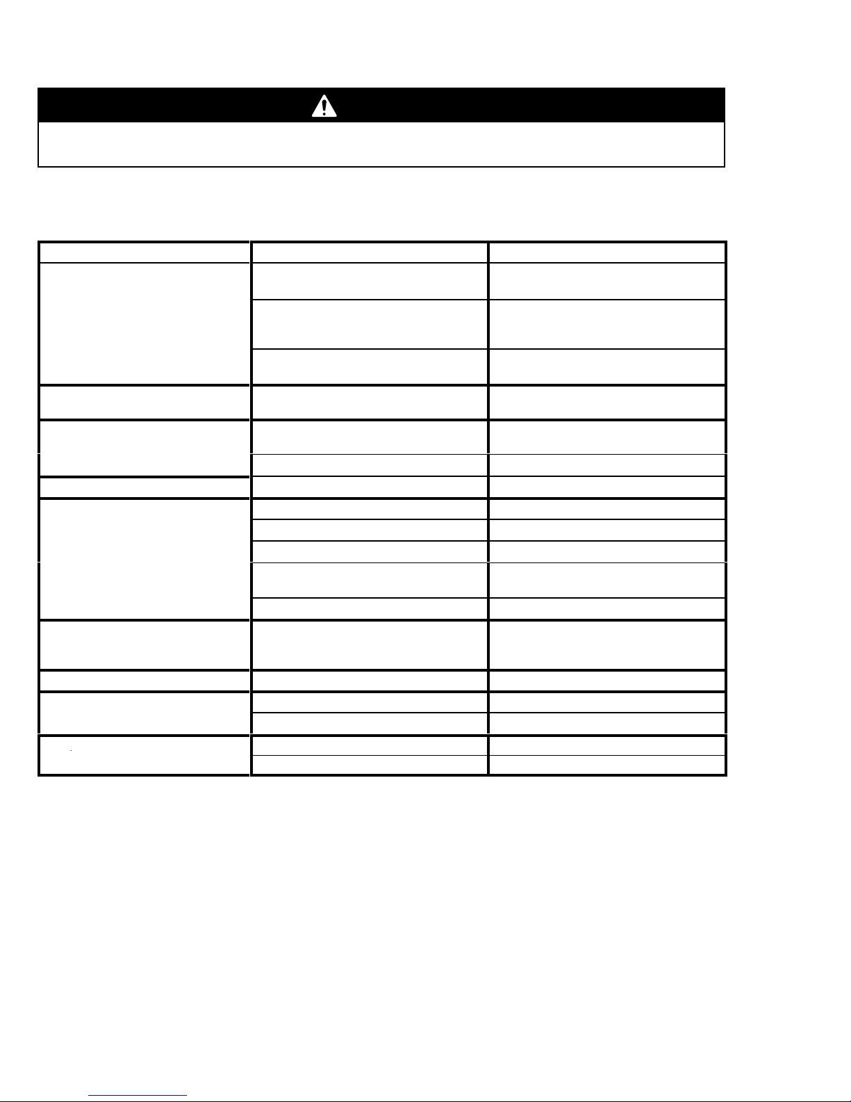
Troubleshooting
p
WARNING
To
reduce the risk of serious injury whenever you are instructed to relieve pressure, always follow the
Pressure Relief Procedure
on page 5.
See the
Troubleshooting
section of instruction manual 308–718 before you proceed with the table below
all possible problems and causes before you disassemble the pump.
PROBLEM CAUSE SOLUTION
Pump will not cycle, or cycles once
and stops.
Pump cycles at stall, or fails to hold
pressure at stall.
Excessive air leakage from exhaust
port, or air exhausts at stall.
Pump operates erratically
Air bubbles in fluid.
Fluid in exhaust air
Pump exhausts air from clamps.
Pump exhausts air near air valve.
Pump leaks fluid from check valves.
. Sticky or leaking duckbill valves (52).
.
Air valve (200) is stuck or dirty.
Broken or damaged springs (209, 212)
and/or valve cup (210) and plate (13).
W
orn or broken detent link (213).
Leaky duckbill valves (52).
W
orn air valve cup (210) or plate (13). Repair or replace.
W
orn shaft seals (30).
Suction line is loose.
Diaphragm (60) is ruptured.
Loose manifold (102) or adapters (57)
Manifold o-rings (50) or adapter o-rings
(53) are leaking.
Loose outer diaphragm plates (1
Diaphragm (60) is ruptured, or dia
phragm plates (1
cracked.
Clamps (109) are loose.
Air valve screws (10) are loose. Tighten screws.
Air valve o-ring (201) is damaged.
Adaptors (57) are loose.
W
orn or damaged o-rings (50).
18, 1
16) are loose or
18). T
-
Disassemble, clean, and lube air valve.
See page 9.
Repair or replace components, or re
place complete air valve (kit 237–683).
See page 7.
Replace detent link and ball (207), or
complete air valve (kit 237–683).
Repair or replace.
Repair or replace.
Repair or replace.
Tighten.
Replace.
T
ighten bolts (59, 105).
Replace.
ighten.
Replace diaphragm and/or tighten
plates.
T
ighten clamps.
Inspect; replace.
T
ighten bolts (59).
Inspect; replace.
. Check
-
See page 12.
See page 9.
See page 14.
See page 12.
See page 13.
See page 5.
See page 12.
See page 14.
See page 14.
See page 5.
See page 7.
See page 8.
See page 12.
See page 12.
6 308-781
Page 7

Pump
Repair – Air V
Replacing the Air Valve
WARNING
To
reduce the risk of serious injury whenever you
are instructed to relieve pressure, always follow the
Pressure Relief Procedure
NOTE:
included in the kit are shown with a dagger (
Ref. No. A tube of general purpose grease is supplied
in the kit. Replace the air valve as follows:
1.
2.
3.
Air V
alve Kit 237–683 is available. Parts
Relieve the pressure.
Unscrew the six mounting screws (10), and
remove the air valve (200). See Fig. 2.
Use an o-ring pick to remove the bearing (125).
Remove the lower link bearing (24). See Fig. 3.
on page 5.
) after the
alve
4.
Remove the two screws (23) holding the valve
plate (13) to the pump. Use an o-ring pick to
remove the valve plate and seal (12). Clean and
inspect the parts. Replace any worn ones. See
Fig. 3.
5.
If the pilot pins (26) are accessible from the inside
of the pump housing (2), pull them out. See Fig. 3.
If not accessible, disassemble the fluid section as
explained on pages 13 to 15.
NOTE:
(27) in place. Removal will destroy the bearings and is
not required unless they are damaged. T
bearings, first perform steps 4 and 5 on page 13.
6.
Inspect the pilot pin o-rings (28) and bearings
o service the
Use a 1/8 in. EZY
(27) from the housing (2). See Fig. 10 on page 14
for an illustration of how to use an EZY
Remove the o-rings (28). Clean and inspect the
parts. Replace any worn parts.
-OUT to remove the bearings
-OUT.
200
201
orque oppositely and evenly to 20 to 25 in-lb (2.3 to 2.8 N.m).
T
Apply grease.
GREASE APPLICA
TION
214
217
218
10
Fig. 2
7325A
05524
Page 8

Pump
Repair – Air V
alve
NOTE:
were not removed, go to step 8.
7.
8.
9.
10.
If the pilot pin o-rings (28) and bearings (27)
Grease the o-rings (28) and install them in the
bearings (27). Press the bearings and o-rings in
place so the bearings are flush with the surface of
the housing (2). See Fig. 3.
Grease the pilot pins (26), and install them from
the inside of the housing (2). See Fig. 3.
Install the seal (12) in the pump housing (2). Install
the valve plate (13), and secure it with the two
screws (23). T
to 0.8 N.m). See Fig. 3.
Apply grease to the bearings (125 and 24). Install
the bearing (125) in the pump housing (2).
Reinstall the lower bearing (24). See Fig. 3.
orque the screws to 5 to 7 in-lb (0.6
11.
Make certain the o-ring (201) is in good condition
and in place on the air valve cover (206).
12.
Apply grease where shown in Fig. 2.
13.
Align the new air valve assembly so the reset
screw (214) is at the bottom. Check that the pilot
pins (26) inside the pump housing (2) give
clearance for the actuator link (217). Install the six
screws (10), and torque them oppositely and
evenly to 20 to 25 in-lb (2.3 to 2.8 N.m).
CAUTION
If you are replacing the diaphragms (60), you
reinstall the air valve before installing the dia
phragms, as the diaphragms will force the pilot pins
into the air valve area.
27
4
must
-
2
1
orque to 5 to 7 in-lb (0.6 to 0.8 N.m).
T
2
Apply grease.
4
Press-fit flush with surface of housing (203).
Fig. 3
2
28
2
24
2
26
12
13
23
1
125
2
04233
Page 9

Pump
Repair – Air V
Disassembly
WARNING
To
reduce the risk of serious injury whenever you
are instructed to relieve pressure, always follow the
Pressure Relief Procedure
on page 5.
alve
4.
Remove the screw (219) and shift saddle (218).
See Fig. 4.
5.
Disassemble the link assembly
actuator link (217), spacer (220), detent link (213),
spring (212), stop (21
1), and valve cup (210).
, consisting of the
NOTE:
included in the kit are shown with a dagger (
Ref. No. A tube of general purpose grease is supplied
in the kit.
1.
2.
3.
Air V
alve Kit 237–683 is available. Parts
) after the
Relieve the pressure.
Remove the air valve (200) as explained on
page 7.
Remove the screw (221) and the reset shaft
handle (222).
206
208
221
6.
Remove the detent ball (207) and spring (209).
The detent collar (208) is a press-fit and should not
need removal; if it does require replacement, you
should also replace the cover (206).
7.
Remove the reset shaft (214), o-ring (215) and
washer (216).
8.
Clean all parts, and inspect them for wear or
damage. Replace as needed. See
on page 10.
201
209
207
210
213
Reassembly
212
215
216
222
Fig. 4
214
220
217
211
218
219
05525
9308-781
Page 10

Pump
Repair – Air V
Reassembly
1.
If
the detent collar (208) was removed,
new collar in a new cover (206). Using a rubber
mallet, carefully press fit the detent collar (208)
into the cover (206). See Fig. 5.
2.
Grease the detent spring (209) and place it in the
collar (208). Grease the ball (207) and set it on the
spring. See Fig. 5.
3.
Apply grease to the o-ring (215), and install it in
the hole in the air valve cover (206), as shown in
Fig. 5. Slide the washer (216) onto the blunt end of
the reset shaft (214). Insert the shaft through the
air valve cover (206) until it seats.
4.
Grease the spring (212). Place the link stop (21
inside the spring. See Fig. 6.
5.
Grease the detent link (213) and link spacer (220).
Assemble the detent link, link spacer
link (217) as shown in Fig. 6. The raised bumps on
the links (213 and 217) must face up.
6.
Squeeze the spring (212), and install it and the
stop (21
spring tension will hold all these parts together
Grease the valve cup (210) and install it in the link
assembly as shown.
1) in the link assembly
. See Fig. 6. The
install a
, and actuator
alve
206
207
216
209
214
05526
208
215
1)
Apply grease.
Press fit.
Fig. 5
.
Page 11

Pump
Repair – Air V
alve
7. Install
the link assembly onto the air valve cover
(206) so the pointed end of the reset shaft (214)
fits through the holes in the links, and the square
part of the reset shaft engages the square hole in
the detent link (213). Make certain the bumps on
the detent link engage the detent ball (207). See
Fig. 6.
1
Apply grease.
2
Bumps face up.
Reset shaft square must
3
engage with square hole.
206
207
211
213
210
212
1
2
1
1
217
2
1
Apply grease.
T
orque to 8 to 14 in-lb
2
(0.9 to 1.6 N.m).
206
222
221
Fig. 7
213
1
210
1
201
218
1
1
214
2
219
05528
Fig. 6
8.
Grease the inside surfaces of the shift saddle
(218), and install it as shown in Fig. 7. Hold the link
assembly firmly in place, and install the screw
(219). T
orque to 8 to 14 in-lb (0.9 to 1.6 N.m).
Install the o-ring (201) on the cover (206).
3
9.
Install the screw (221) and the reset shaft handle
(222) on the reset shaft (214).
1
220
05527
10.
Reinstall the air valve as explained on page 8.
Page 12

Pump
Repair – Duckbill V
alves
NOTE: Duckbill V
Use all the parts in the kit.
Install Duckbill V
1.
Relieve the pressure.
alve Repair Kit 239–754 is available. Kit parts are shown with two asterisks (**) after
alve Repair Kit 239–754 as follows.
See Fig. 8:
WARNING
T
o reduce the risk of serious injury whenever you are instructed to relieve
pressure, always follow the
2.
Remove the pump from the spray unit.
3.
Stand the pump upright on the floor or workbench.
Disassembly
4.
Remove the bolts (59), washers (107), and nuts (106) with a
9/16” wrench, and remove the two adapters (57) and the
adapter o-rings (53).
5.
Remove the exposed duckbill valves (52), spacers (51), and
o-rings (50).
Pressure Relief Procedure
on page 5.
57
106
the Ref. No.
59
107
**53
**52
**51
**50
6. T
urn the pump so it is standing upside down on the floor or
workbench.
7.
Remove the manifold bolts (105) and nuts (106) with a 9/16”
wrench, and remove the feet (108) and the manifold (102).
8.
Remove the exposed o-rings (50), spacers (51), and duckbill
valves (52).
Reassembly
1.
With the pump standing upside down on the floor or
workbench, install the lower duckbill valve assembly by
inserting the new duckbill valves (52), spacers (51), and
o-rings (50).
2.
Reassemble the manifold (102), feet (108), bolts (105), and
nuts (106), and torque the bolts to 3 to 6 ft-lb (4 to 8 N-m).
3. T
urn the pump so it is standing upright on the floor or
workbench.
4.
Install the upper duckbill valve assembly by inserting the new
o-rings (50), spacers (51), and duckbill valves (52).
5.
Reinstall the two adapters (57), the new adapter o-rings (53),
bolts (59), washers (107), and nuts (106), and torque the bolts
to 3 to 6 ft-lb (4 to 8 N-m).
101
106
**52
**51
**50
102
108
6.
Reinstall the pump on the spray unit.
T
orque to 3 to 6 ft-lb
(4 to 8 N-m).
Fig. 8
105
7326A
Page 13

Pump
Repair – Diaphragm
Disassembly
WARNING
To
reduce the risk of serious injury whenever you
are instructed to relieve pressure, always follow the
Pressure Relief Procedure
NOTE:
parts are shown with a double dagger () after the Ref.
No. Use all parts in the kit.
NOTE:
extractor to remove the bearings (31). Other removal
methods may damage the pump housing (2).
NOTE:
(27) in place. Removal will destroy the bearings and is
not required unless they are damaged. T
bearings, see step 6 on page 7.
1.
2.
Diaphragm Shaft Kit 239–016 is available. Kit
In Step 6, use a 13/32 in. EZY
Inspect the pilot pin o-rings (28) and bearings
Relieve the pressure.
Remove the pump from the spray unit.
on page 5.
-OUT (B) screw
o service the
5.
Unscrew one outer plate (1
shaft (29). Remove one diaphragm (60) and inner
plate (1
and the shaft out of the pump housing (2). See
Fig. 9. Clamp the shaft in a vise with soft jaws (or
grip the flats with a wrench) and unscrew the outer
plate (1
diaphragm assembly
6.
Inspect the shaft (29) for wear or scratches. If it is
damaged, check the bearings (31) also. Replace
parts as needed. T
13/32 EZY
Fig. 10. Position the pump housing (2) over the
EZY-OUT. T
by the arrows to remove the bearing.
7.
Hook the shaft seals (30) with an o-ring pick, and
pull them out of the housing (2).
8.
Clean all parts, and inspect for wear or damage.
Replace parts as needed.
16). Pull the opposite diaphragm assembly
18), then disassemble the remaining
o remove the bearings, place a
-OUT (B) in a vise (C), as shown in
urn the housing in the direction shown
18) from the diaphragm
.
3.
Remove the clamp nuts (1
(109).
4.
Remove the bottom manifold (102), and pull the
covers (101) of
Do not lose the manifold o-rings. See Fig. 8.
f the pump. See Fig. 9.
10) and the clamps
Page 14

Pump
Repair – Diaphragm
1
Grease
.
medium-strength (blue) LoctiteR or equivalent. T
Apply
3
75 to 85 in lb (8.5 to 9.6 N.m). Do not over-torque.
T
orque to 3 to 6 ft-lb (4 to 8 N-m).
5
56*
3
57
101
55*
orque to
102
1
118*
‡29
60
‡31
116*
109
101
110
2
30‡
5
105
Fig.
9
Reassembly
CAUTION
If
you have removed the air valve (200), you
reinstall it before you reinstall the diaphragms (60).
See pages 7 and 8.
1.
Grease the shaft seals (30) and install them in the
housing (2). Using a rubber mallet, carefully drive
the bearings (31) flush into the housing so the
holes face out. See Fig. 10.
2.
Grease the diaphragm shaft (29), and slide it into
the housing (2). See Fig. 1
1.
must
108
Fig.
C
10
7328A
Holes
1
face out of housing (2).
}30
1
}31
B
2
03423A
14 308-781
Page 15

Pump
Repair – Diaphragm
3. Assemble
diaphragms (60), and outer diaphragm plates
(118)
medium-strength (blue) LoctiteR or equivalent to
the outer diaphragm plate threads, and torque to
75 to 85 in-lb (8.5 to 9.6 N.m).
over-torque.
correctly.
the inner diaphragm plates (1
exactly
as shown in Fig. 1
These parts
must
16),
1. Apply
Do not
be assembled
CAUTION
Do not over-torque the outer diaphragm plates (1
Overtorqueing could damage the hex-head screws.
4.
Install the lower manifold (102) on
covers (101), making sure you have the o-ring (50)
in place (See Fig. 8).
5.
Install the the pump housing (2) on this cover
clamp bolts should be on the air valve side of the
housing, and the housing should be oriented as
shown in Fig. 9. Apply thread lubricant to the
clamp bolt, and tighten the clamp nut (1
tight.
one
of the
10) hand
18).
. The
The
3
4
5
6
words “AIR SIDE” on diaphragm (60)
must face into the pump housing (2).
Flat side of plates (1
Apply medium-strength (blue) LoctiteR or equivalent.
T
orque to 75 to 85 in-lb (8.5 to 9.6 N.m).
over-torque.
Grease.
16) must face center of pump.
Do not
3
2
3
60
29}
6
6.
Install the remaining cover (101) onto the lower
manifold (102), and tighten the manifold bolts
lightly; do not torque yet.
7.
Install the remaining clamp (109), apply thread
lubricant to the clamp bolt. T
nuts (110) to 75 to 85 in-lb (8.5 to 9.6 N.m).
8. T
orque the top adapter bolts (59) and the lower
manifold bolts (105) to 3 to 6 ft-lb (4 to 8 N-m).
See Fig. 9.
9.
Reinstall the pump on the spray unit.
orque both clamp
*118
5
Fig. 11
*116
04945
4
15308-781
Page 16

Parts
PTFE
List
Model 239–421, Series A
Ref.
No.
2 189–531 HOUSING, center 1
10 112–545 SCREW
12 187–719
13 187–720 PLATE, valve; sst; 1
23 112–546 SCREW
24 190–244 BEARING, link, lower 1
26 188–849
27 188–850 BEARING, pin 2
28 157–628 O-RING; buna-N 2
29‡ 191–780 SHAFT
30‡ 113–704 PACKING, o-ring; Viton 2
31‡ 191–779 BEARING, acetal 2
50** 110–782 O-RING; buna-N 4
51** 192–138 SPACER; DelrinR 4
52** 192–137 VAL
53** 154–662 O-RING; buna-N 2
54 290–039 PLA
55* 110–004 O-RING; R 2
56* 113–747 SCREW
57 192–140 ADAPT
58 189–801
59 113–976 SCREW, HHCS;
60 190–148 DIAPHRAGM; buna–N 2
101 185–622
102 185–624
103Y 189–220
105 112–912 SCREW
106 112–913 NUT
107 112–914 WASHER, flat; 3/8”; sst 4
108 186–207 FEET 2
109 189–540 CLAMP 2
110 112–499 NUT
112 102–726 PLUG; steel 1
116* 191–741 PLA
117Y 186–205
Part No. Description Qty
, thread-forming;
M5 x 0.8; 16 mm long
SEAL, plate, valve; buna-N
, machine; 4–40;
3/8” (10 mm) long
PIN, pilot
, diaphragm; sst
VE, duckbill; buna-N
TE, identification
, flange, hex;
1/4–20 x 1” (25.4 mm)
OR; aluminum
LABEL, identification
3/8–16 x 1.5” (38.1 mm)
COVER, fluid; aluminum
MANIFOLD; aluminum
LABEL, warning
; 3/8–16;
2.25” (57.2 mm) long
, hex; 3/8–16; sst
, clamp; 1/4–28
TE, diaphragm, inner; sst
LABEL, warning
Ref.
No.
118* 191–837 PLA
6
1
2
2
1
4
1
2
2
1
4
2
1
1
4
8
2
2
1
124 111–881 MUFFLER 1
125 187–726 BEARING, link; acetal 1
200 237–683 AIR VALVE
201{ 111–624 O-RING; buna-N 1
206{ 187–706 COVER, air valve;
207{ 111–629
208{ 187–730 COLLAR, detent; sst 1
209{ 187–728
210{ 187–725 CUP
211{ 187–853 STOP
212{ 187–722 SPRING; sst 1
213{ 190–692
214{ 190–332 SHAFT
215{ 111–625 O-RING; buna-N 1
216{ 111–750 WASHER, plain; sst 1
217{ 187–724 LINK, actuator; sst 1
218{ 187–718
219{ 111–630 SCREW
220 188–175 SP
221{ 112–788 SCREW
222{ 190–333 HANDLE, reset shaft 1
223{ 187–731
301 113–444 ELBOW
302 113–668
303 169–970
304 192–139 NIPPLE,
{
‡
*
*
*
Y
Part No. Description Qty
TE, diaphragm, outer; sst
Contains Ref. No. 201 to 223.
polypropylene
BALL, detent; carbide
SPRING, detent; SST
, valve; acetal
, link; acetal
LINK, detent; sst
, reset; stainless steel
SADDLE, shift; acetal
10–14 x 0.75” (19 mm)
8–32 x 0.375” (9.5 mm)
LABEL, identification
(not shown)
COUPLER, female; alum; 1”
FITTING, air line
x
These parts are included in Air V
may be purchased separately
These parts are included in Diaphragm Shaft Kit
239–016, which may be purchased separately
These parts are included in Diaphragm Plate Kit
239–141, which may be purchased separately
These parts are included in Duckbill V
239–754, which may be purchased separately
Replacement Danger and W
are available at no cost.
, thread-forming;
ACER, link; acetal
, cap, socket head;
, street, 45
pipe, hex; 3/4
3/4 npt(m); aluminum
. See
arning labels, tags and cards
_; brass 1
alve Kit 237–683, which
Detail
alve Repair Kit
npt(m)
on page 17.
.
.
.
2
1
1
1
1
1
1
1
1
1
1
1
1
1
1
1
1
16 308-781
Page 17

Model 239–421, Series A
59
107
**53
57
**52
**51
See
10
58
200
Detail
Parts
23
27
Drawing
12
125
26
24
28
13
2
109
101
54
110
302
106
Y103
Y117
106
304
**50
101
**52
**51
**50
112
56*
55*
102
118*
221{
60
116*
31‡
30
‡
Detail
206{
29
‡
of Air V
208{
124
alve, Ref. No. 200
201
{
209
207{
210{
213{
220
301
7327A
217{
303
212{
211{
105
{
Part of Air V
‡ Part if Diaphragm Shaft Kit 239–016.
* Part of Diaphragm Plate Kit 239–141.
** Part of Duckbill V
alve Kit 237–683.
alve Repair Kit 239–754.
108
222{
{215
{216
{214
218{
219{
05525
Page 18

Notes
Page 19

Technical
PTFE
Data
Technical
operating conditions.
Maximum air and fluid working pressure 100 psi (0.7 MPa, 7 bar)
Air
pressure operating range
Maximum
Maximum
Maximum
Gallons
Maximum
Maximum
Wetted
Non-wetted
Weight 11
Maximum
Air
inlet size
Fluid
Loctite
air consumption
free flow delivery
pump speed 200 cpm
(liters) per cycle
suction lift
size pumpable solids
parts
outlet size
R
. . . . . . . . . . . . . . . . . . . . . . . . . . . . . . . . . . . . . . . . . . . . . . . . . . . . . . . . . . . .
external parts
.
. . . . . . . . . . . . . . . . . . . . . . . . . . . . . . . . . . . . . . . . . . . . . . . . . . . . . . . . . . . . . . . . . . . . . . . . . . . . . . . . . . .
operating temperature
. . . . . . . . . . . . . . . . . . . . . . . . . . . . . . . . . . . . . . . . . . . . . . . . . . . . . . . . . . . . . . . . . . . . . . . . . . . . . . . . .
. . . . . . . . . . . . . . . . . . . . . . . . . . . . . . . . . . . . . . . . . . . . . . . . . . . . . . . . . . . . . . . . . . . . . . . . . . . . . .
is a registered trademark of the Loctite Corporation.
, V
iton
R
, and Delrin
Data based on tests with water
.
. . . . . . . . . . . . . . . . . . . . . . . . . . . . . . . . . . . . . . . . . . . .
.
. . . . . . . . . . . . . . . . . . . . . . . . . . . . . . . . . . . . .
. . . . . . . . . . . . . . . . . . . . . . . . . . . . . . . . . . . . . . . . . . . . . . . . . . . . . . .
.
. . . . . . . . . . . . . . . . . . . . . . . . . . . . . . . . . . . . . . . . . . . . . . . . . . . . . . . . . . . . . .
.
. . . . . . . . . . . . . . . . . . . . . . . . . . . . . . . . . . . . . . . . . . . . . . . . . . . . . . . . . . . . . . . . . . . . . . . . .
. . . . . . . . . . . . . . . . . . . . . . . . . . . . . . . . . . . . . . . . . . . . . . . . . . . . . . . . . . . . . . . . . . . . . .
.
. . . . . . . . . . . . . . . . . . . . . . . . . . . . . . . . . . . . . . . . . . . . . . . . . . . . .
.
. . . . . . . . . . . . . . . . . . . . . . . . . . . . . . . . . . . . . . . . . . . . . . . . . . . . . . . . . .
.
. . . . . . . . . . .
.
R
aluminum, 303 stainless steel, polyester (labels), polyethylene, zinc-plating
. . . . . . . . . . . . . . . . . . . . . . . . . . . . . . . . . . . . . . . . . . . . . . . . . . . . . . . . .
. Data varies with different materials and
25 to 100 psi (0.17 to 0.7 MPa, 1.7 to 7 bar)
19 SCFM (0.523 m3/min).
16 ft (4.8 m) dry; 25 ft (7.6 m) wet
aluminum, SST
14 gpm (53 lpm)
0.08 (0.3).
1/4 in. (6.4 mm)
, buna–N, Delrin
lb (5.0 kg)
100_ F ( 37_
1/4 npt(f).
3/4 npt(f).
R.
C)
19308-781
Page 20

Graco
Graco
warrants all equipment listed in this manual which is manufactured by Graco and bearing its name to be free from defects in
material
any
replace
operated
This
faulty installation, misapplication, abrasion, corrosion, inadequate or improper maintenance, negligence, accident, tampering, or
substitution
Graco
installation,
This
verification
equipment
in
transportation.
Graco’s
remedy (including, but not limited to, incidental or consequential damages for lost
other incidental or consequential loss) shall be available. Any action for breach of warranty must be brought within two
date
GRACO
A PARTICULAR PURPOSE IN CONNECTION WITH ACCESSORIES, EQUIPMENT
NOT MANUFACTURED BY GRACO. These items sold, but not manufactured by Graco (such as electric motors, gas engines,
switches,
in
In
hereunder,
breach
and workmanship on the date of sale by an authorized Graco distributor to the original purchaser for use. With the exception
special extended or limited warranty published by Graco, Graco will,
any part of the equipment determined by Graco to be defective. This warranty applies only when the
and maintained in accordance with Graco’
warranty does not cover
of non-Graco component parts. Nor shall Graco be liable for malfunction, damage or wear caused by the incompatibility of
equipment with structures, accessories, equipment or materials not supplied by Graco, or the
operation or maintenance or structures, accessories, equipment or materials not supplied by Graco.
warranty is conditioned upon the prepaid return of the equipment claimed to be defective to an authorized Graco distributor for
of the claimed defect. If the claimed defect is verified, Graco will repair or replace free of charge any defective parts. The
will be returned to the original purchaser transportation prepaid. If inspection of the equipment does not disclose any defect
material or
of sale.
making any claim for breach of these warranties.
no event will Graco be liable for indirect, incidental, special or consequential damages resulting from Graco supplying equipment
workmanship, repairs will be made at a reasonable charge, which charges may include the costs of parts, labor
sole obligation and buyer’s sole remedy for any breach of warranty shall be as set forth above.
MAKES NO W
hose, etc.), are subject to the warranty
or the furnishing, performance, or use of any products or other goods sold hereto, whether due to a breach of contract,
of warranty
, the negligence of Graco, or otherwise.
, and Graco shall not be liable
ARRANTY
, AND DISCLAIMS ALL
s written recommendations.
, if any
W
arranty
for a period of twelve months from the date of sale, repair or
for general wear and tear
IMPLIED W
, of their manufacturer
ARRANTIES OF MERCHANT
equipment is installed,
, or any malfunction, damage or wear caused by
improper design, manufacture,
, and
The buyer agrees that no other
profits,
lost sales, injury to person or property
(2)
ABILITY AND FITNESS FOR
, MA
TERIALS OR COMPONENTS SOLD BUT
. Graco will provide purchaser with reasonable assistance
, or any
years of the
of
FOR
GRACO CANADA CUST
The
parties acknowledge that they have required that the present document, as well as all documents, notices and legal proceedings
entered into, given or instituted pursuant hereto or relating directly or indirectly hereto, be drawn up in English. Les parties
reconnaissent
judiciaires
TO
PLACE AN ORDER
avoir convenu que la rédaction du présente document sera en Anglais,
exécutés, donnés ou intentés à la suite de ou en rapport, directement ou indirectement, avec les procédures concernées.
OMERS
Graco
Phone Number
, contact your Graco distributor
1–800–367–4023 T
ainsi que tous documents, avis et procédures
, or call this number to identify the distributor closest to you:
oll Free
All
written and visual data contained in this document reflects the latest product information available at the time of publication.
Graco reserves the right to make changes at any time without notice.
Foreign Offices:
Sales Offices:
Belgium, Canada, England, Korea, France, Germany
GRACO INC. P.O. BOX 1441
PRINTED
Minneapolis, Detroit, Los Angeles
MINNEAPOLIS, MN
IN U.S.A. 308–781 June 1997
, Hong Kong, Japan
55440–1441
 Loading...