

Page 1
Instructions - Parts List
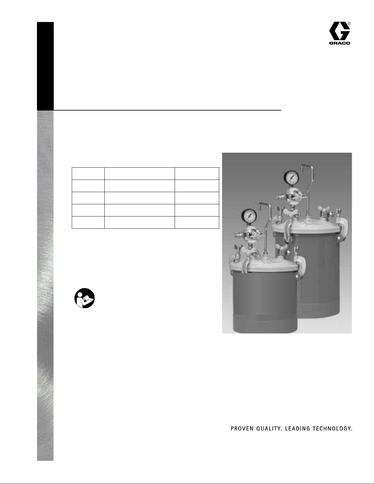
2.5 and 5.0 Gallon
Pressure Tank
- Not for use with highly abrasive, corrosive, or rust inducing materials -
Model Capacity Regulation
309926G
234414
234415
234416
234417
50 psi (345 kPa, 3.5 bar) Maximum Fluid Pressure*
*Air pressure loads that are higher than design loads
or alterations to the pressure feed tank, can result in
tank rupture or explosion.
Important Safety Instructions
Read all warnings and instructions in this manual.
Save these instructions.
2.5 gal. (9.5 liter) single
2.5 gal. (9.5 liter) dual
5 gal. (19 liter) single
5 gal. (19 liter) dual
Graco Inc. P.O. Box 1441 Minneapolis, MN 55440-1441
Copyright 2003, Graco Inc. is registered to I.S. EN ISO 9001
Page 2
Manual Conventions
Manual Conventions
WARNING
WARNING indicates a potentially hazardous situation
which, if not avoided, could result in death or serious
injury.
FIRE AND EXPLOSION HAZARD
Flammable fumes, such as solvent and paint fumes, in work area can ignite or explode. To help prevent
fire and explosion:
• Use equipment only in well ventilated area.
• Eliminate all ignition sources, such as pilot lights, cigarettes, portable electric lamps, and plastic drop
cloths (potential static arc).
• Keep work area free of debris, including solvent, rags, and gasoline.
• Do not plug or unplug power cords or turn lights on or off when flammable fumes are present.
• Ground equipment and conductive objectives. See Grounding in your sprayer manual.
• Use only grounded hoses.
• Hold gun firmly to side of grounded pail when triggering into pail.
• If there is static sparking or you feel a shock, stop operation immediately. Do not use equipment
until you identify and correct the problem.
CAUTION
CAUTION indicates a potentially hazardous situation
which, if not avoided, may result in property damage or
destruction of equipment.
Note
A note indicates additional helpful information.
WARNING
EQUIPMENT MISUSE HAZARD
Misuse can cause death or serious injury.
• Do not exceed maximum working pressure or temperature rating of the lowest rated system component. See Technical Data in all equipment manuals.
• Use fluids and solvents that are compatible with equipment wetted parts. See Technical Data in all
equipment manuals. Read fluid and solvent manufacturer’s warnings.
• Check equipment daily. Repair or replace worn or damaged parts immediately.
• Do not alter or modify equipment.
• Use equipment only for its intended purpose. Call your Graco distributor for information.
• For professional use only.
• Route hoses and cables away from traffic areas, sharp edges, moving parts, and hot surfaces.
• Comply with all applicable safety regulations.
TOXIC FLUID OR FUMES HAZARD
Toxic fluids or fumes can cause serious injury or death if splashed in the eyes or on skin, inhaled, or swallowed.
• Read MSDS’s to know the specific hazards of the fluids you are using.
• Store hazardous fluid in approved containers, and dispose of it according to applicable guidelines.
PERSONAL PROTECTIVE EQUIPMENT
You must wear appropriate protective equipment when operating, servicing, or when in the operating
area of the equipment to help protect you from serious injury, including eye injury, inhalation of toxic
fumes, burns, and hearing loss. This equipment includes but is not limited to:
• Protective eye wear
• Gloves, clothing and respirator as recommended by the fluid and solvent manufacturer
• Hearing protection
2 309926G
Page 3

Set-Up
Set-Up
Pressure Relief Procedure
WARNING
Pressure tanks remain pressurized until pressure is
manually relieved. To reduce the risk of serious injury
from pressurized fluid or accidental spray from gun,
always follow this procedure to relieve pressure in the
tank:
• Before you check or service any part of the spray
system.
• Before you loosen or remove the pressure tank
cover or fill port.
• Whenever you stop spraying.
1. Shut off air supply to the tank by closing air valve.
2. Pull ring on safety valve until pressure bleeds down.
Material Preparation
Follow manufacturer’s directions for mixing and
preparing material.
Strain material using a fine mesh screen to prevent
foreign matter from entering and clogging passageways.
Tank Assembly
1. Install tank handle and lock nut by turning handle
clockwise 4-5 turns. Position handle so it is parallel
to safety valve branch tee.
2. Secure in place by tightening lock nut using a 9/16
in. open end wrench.
Tank handle must be attached before installing
regulator.
3. Install regulator 234393 by tightening swivel adapter
nut 288804 onto nipple 288778. Position unit so
gauge is facing the same direction as safety valve
ring. Use 11/16 in. open end wrench to tighten
swivel adapter nut.
309926G 3
Page 4

Installation
Installation
WARNING
• A safety valve protects tank from over pressurization. During each use, pull ring on safety valve to
check if it operates freely and relieves air pressure.
If the valve is stuck, does not operate freely, or does
not relieve air pressure, it must be replaced.
• Do not discard or make any alterations or substitutions to safety valve.
• Do not make any changes to the pressure tank.
Tampering in the form of drilling, welding, etc., will
weaken the tank.
The following information is for a typical
installation.
3. Pour material into tank.
Use part no. 289136 2.5 Gallon Disposable Tank
Liners for easy clean-up. Not available for 5 Gallon
Ta nk .
4. Replace lid assembly and tighten clamps and thumb
screws securely.
5. Pass air supply line through Air Control Unit to filter
dirt from air and extract water and oil. Connect air
supply hose to air inlet fitting on tank regulator.
6. Attach atomization air hose to the air outlet fitting
which is directly opposite air inlet fitting on tank
pressure regulator.
1. Follow Pressure Relief Procedure, page 3.
2. Slowly loosen thumb screws, tip lid clamps back and
remove lid assembly.
MADEIN USA
971
7. Connect material hose to fluid outlet fitting on top of
tank lid.
4 309926G
Page 5

Operation
Operation
1. Turn on air supply.
2. Turn T-handle adjusting screw clockwise on the tank
pressure regulator, while pulling the gun trigger fully
back to start material flow.
3. Continue turning T-handle clockwise until desired
material flow is achieved. To decrease pressure turn
T-handle counter-clockwise to a lower setting. Then
relieve pressure in tank by pulling the ring on the
safety valve.
4. Atomization air for the spray gun can be adjusted
using the air adjusting valve on the spray gun or at
the air regulator assembly (Model 234415 only) on
the pressure tank.
5. Operate spray gun according to instructions
accompanying gun.
Maintenance
9. Pour solvent into tank.
10. Replace lid and tighten thumb screws and clamps.
11. Turn T-handle on tank regulator clockwise while
pulling gun trigger fully back and spray until clean
solvent appears.
12. Repeat steps 1-3.
Decorative powder coating may be affected by
solvent contact. Avoid prolonged exposure of
solvents to powder coated areas. Tank has been
zinc plated underneath the decorative coating for
rust protection.
Cleaning the Tank
1. Turn off main air supply to tank.
2. Follow Pressure Relief Procedure, page 3.
3. Turn T-handle adjusting screw on regulator,
counter-clockwise until no spring tension is felt.
4. Slowly loosen thumb screws, tip clamps back and
tip tank lid to one side.
5. Loosen spray gun air cap ring about three turns.
6. Turn on air supply.
7. Hold a cloth over air cap on gun and pull trigger.
This forces material back through the hose, into the
tank.
8. Empty and clean tank and parts using a suitable
solvent.
309926G 5
Page 6

Troubleshooting
Troubleshooting
Problem Cause(s) Solution(s)
Air escaping from the hose on regulator bonnet.
Pressure creepage registered on
gauge
Fluid or air leak at lid gasket Defective lid gasket or thumb screws
Broken or damaged diaphragm Replace diaphragm
Dirty or worn valve seat in regulator Clean or replace valve seat
Replace or tighten
not tight
Technical Data
Maximum Fluid Pressure . . . . . . . . . . . . . . . . . . . . . . . . . 50 psi (345 kPa, 3.5 bar)
Air Inlet . . . . . . . . . . . . . . . . . . . . . . . . . . . . . . . . . . . . . . . 1/4” nps
Fluid Outlet . . . . . . . . . . . . . . . . . . . . . . . . . . . . . . . . . . . . 3/8” nps
Wetted Parts. . . . . . . . . . . . . . . . . . . . . . . . . . . . . . . . . . . PTFE-coated steel bowl, zinc-plated pick-up tube,
nickel-plated fluid fitting
6 309926G
Page 7

Parts
Parts
2.5 and 5 Gallon Pressure Tanks, Models: 234414,
234415, 234416, 234417
Part No. Description
157350 ADAPTER, 3/8 npt x 1/4 npt
234393 REGULATOR, air pressure
289134 TUBE fluid (234414 & 234415 only)
289141 TUBE, fluid (234416 & 234417 only)
289144 LID, assembly
288803 LID, gasket, thiokol
116306 VALVE, safety
288804 ADAPTER, swivel
289161 TEE, branch
288805 HANDLE, tank
288806 NUT, hex, handle
289145 NIPPLE, fluid, 3/8 in.
289146 ELBOW, street
289147 YOKE, assembly, with thumbscrew
289148 PIN, hinge with “E” clip
234392 REGULATOR, air pressure (234415 &
234417 only)
160430 GAUGE, air pressure
289149 PLUG
157350 ADAPTER, 3/8npt x 1/4 npt
234393 Regulator
Part No. Description
160430 GAUGE, fluid pressure
288778 NIPPLE, 1/4 in.
289150 REGULATOR, body
289151 REGULATOR, bonnet
289152 SEAT, valve
289153 SPRING, valve
289154 BODY, valve
288779 STEM, valve
289155 SCREEN, wire
288780 DIAPHRAGM, assembly
289156 SPRING, pressure
289157 WASHER, spring
289158 DAMPER, vibration
289159 SCREW, adjusting
289160 SCREW
Accessories
289136 TANK LINER, not shown (234414 and
234415 only), 2.5 gal. only
234393
288804
289161
116306
289144
288803
288805
234415 & 234417
additional components
157350
288806
Model 234414 shown
289149
289145
289134
or
289141
160430
234392
157350
289146
289147
289148
289159
289160
289151
289157
289156
289158
288780
289154
289152
288779
289153
289150
289155
309926G 7
Page 8

Graco Standard Warranty
Graco warrants all equipment referenced in this document which is manufactured by Graco and bearing its name to be free from defects in material
and workmanship on the date of sale to the original purchaser for use. With the exception of any special, extended, or limited warranty published by
Graco, Graco will, for a period of twelve months from the date of sale, repair or replace any part of the equipment determined by Graco to be
defective. This warranty applies only when the equipment is installed, operated and maintained in accordance with Graco’s written
recommendations.
This warranty does not cover, and Graco shall not be liable for general wear and tear, or any malfunction, damage or wear caused by faulty
installation, misapplication, abrasion, corrosion, inadequate or improper maintenance, negligence, accident, tampering, or substitution of
non-Graco component parts. Nor shall Graco be liable for malfunction, damage or wear caused by the incompatibility of Graco equipment with
structures, accessories, equipment or materials not supplied by Graco, or the improper design, manufacture, installation, operation or maintenance
of structures, accessories, equipment or materials not supplied by Graco.
This warranty is conditioned upon the prepaid return of the equipment claimed to be defective to an authorized Graco distributor for verification of
the claimed defect. If the claimed defect is verified, Graco will repair or replace free of charge any defective parts. The equipment will be returned
to the original purchaser transportation prepaid. If inspection of the equipment does not disclose any defect in material or workmanship, repairs will
be made at a reasonable charge, which charges may include the costs of parts, labor, and transportation.
THIS WARRANTY IS EXCLUSIVE, AND IS IN LIEU OF ANY OTHER WARRANTIES, EXPRESS OR IMPLIED, INCLUDING BUT NOT LIMITED
TO WARRANTY OF MERCHANTABILITY OR WARRANTY OF FITNESS FOR A PARTICULAR PURPOSE.
Graco’s sole obligation and buyer’s sole remedy for any breach of warranty shall be as set forth above. The buyer agrees that no other remedy
(including, but not limited to, incidental or consequential damages for lost profits, lost sales, injury to person or property, or any other incidental or
consequential loss) shall be available. Any action for breach of warranty must be brought within two (2) years of the date of sale.
GRACO MAKES NO WARRANTY, AND DISCLAIMS ALL IMPLIED WARRANTIES OF MERCHANTABILITY AND FITNESS FOR A
PARTICULAR PURPOSE, IN CONNECTION WITH ACCESSORIES, EQUIPMENT, MATERIALS OR COMPONENTS SOLD BUT NOT
MANUFACTURED BY GRACO. These items sold, but not manufactured by Graco (such as electric motors, switches, hose, etc.), are subject to
the warranty, if any, of their manufacturer. Graco will provide purchaser with reasonable assistance in making any claim for breach of these
warranties.
In no event will Graco be liable for indirect, incidental, special or consequential damages resulting from Graco supplying equipment hereunder, or
the furnishing, performance, or use of any products or other goods sold hereto, whether due to a breach of contract, breach of warranty, the
negligence of Graco, or otherwise.
FOR GRACO CANADA CUSTOMERS
The Parties acknowledge that they have required that the present document, as well as all documents, notices and legal proceedings entered into,
given or instituted pursuant hereto or relating directly or indirectly hereto, be drawn up in English. Les parties reconnaissent avoir convenu que la
rédaction du présente document sera en Anglais, ainsi que tous documents, avis et procédures judiciaires exécutés, donnés ou intentés, à la suite
de ou en rapport, directement ou indirectement, avec les procédures concernées.
Graco Phone Numbers
TO PLACE AN ORDER, contact your Graco distributor or call to identify the nearest distributor.
Phone: 612-623-6921 or Toll Free: 1-800-328-0211, Fax: 612-378-3505
All written and visual data contained in this document reflects the latest product information available at the time of publication.
Graco reserves the right to make changes at any time without notice.
This manual contains English. MM 309926
Graco Headquarters: Minneapolis
International Offices: Belgium, China, Japan, Korea
GRACO INC. P.O. BOX 1441 MINNEAPOLIS, MN 55440-1441
www.graco.com
309926G 6/2003, Rev. 9/2007
 Loading...