

Page 1
Instructions – Parts List
Parts
120 VAC, 15A
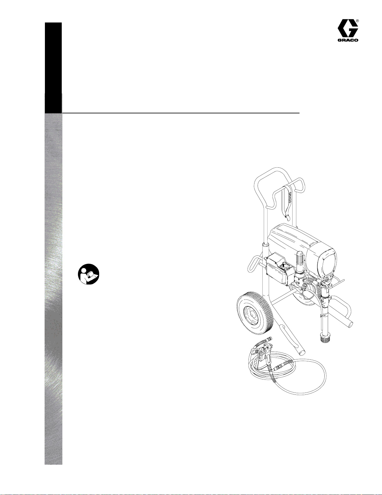
ULTRARMAX 795
Airless Paint Sprayer
3000 psi (21 MPa, 210 bar) Maximum Working Pressure
Model 232140, Series A
Basic sprayer on upright cart without
hose or gun
Model 232141, Series A
Complete sprayer on upright cart with hose,
gun, RAC IV DripLess Tip Guard
and SwitchTip
308800F
U.S. PATENT No. 4,323,741; 4,397,610
PATENTED 1983, CANADA
AND OTHER PATENTS PENDING
Important Safety Instructions
Read all warnings and instructions in this manual.
Save these instructions.
Related Manuals
Displacement Pump 308798. . . . . . . . . . . . . . . . .
Spray Gun 307614. . . . . . . . . . . . . . . . . . . . . . . . .
Spray Tip 308644. . . . . . . . . . . . . . . . . . . . . . . . . . .
7706A
GRACO INC. P.O. BOX 1441 MINNEAPOLIS, MN 55440–1441
Copyright 2002, Graco Inc. is registered to I.S. EN ISO 9001
Page 2

Table of Contents
Warnings 2. . . . . . . . . . . . . . . . . . . . . . . . . . . . . . . . . . . . . .
Component Function and Identification 5. . . . . . . . . . . .
Setup 6. . . . . . . . . . . . . . . . . . . . . . . . . . . . . . . . . . . . . . . . .
Startup 7. . . . . . . . . . . . . . . . . . . . . . . . . . . . . . . . . . . . . . . .
Shutdown and Care 9. . . . . . . . . . . . . . . . . . . . . . . . . . . .
Flushing 10. . . . . . . . . . . . . . . . . . . . . . . . . . . . . . . . . . . . . .
Troubleshooting 11. . . . . . . . . . . . . . . . . . . . . . . . . . . . . . .
Spin Test 17. . . . . . . . . . . . . . . . . . . . . . . . . . . . . . . . . . . . .
General Repair Information 16. . . . . . . . . . . . . . . . . . . . .
Motor Brush Replacement 18. . . . . . . . . . . . . . . . . . . . .
Power Supply Cord Replacement 19. . . . . . . . . . . . . . .
On/Off Switch Replacement 19. . . . . . . . . . . . . . . . . . . .
Pressure Control Repair 21. . . . . . . . . . . . . . . . . . . . . . .
Symbols
Warning Symbol
WARNING
This symbol alerts you to the possibility of serious
injury or death if you do not follow the instructions.
Bearing Housing & Connecting Rod Replacement 24.
Drive Housing Replacement 25. . . . . . . . . . . . . . . . . . . .
Motor Replacement 27. . . . . . . . . . . . . . . . . . . . . . . . . . . .
Displacement Pump Repair 29. . . . . . . . . . . . . . . . . . . . .
Accessories 31. . . . . . . . . . . . . . . . . . . . . . . . . . . . . . . . . .
Technical Data 31. . . . . . . . . . . . . . . . . . . . . . . . . . . . . . . .
Dimensions 31. . . . . . . . . . . . . . . . . . . . . . . . . . . . . . . . . . .
Parts Drawing – Sprayer 32. . . . . . . . . . . . . . . . . . . . . . .
Parts List – Sprayer 33. . . . . . . . . . . . . . . . . . . . . . . . . . .
Wiring Diagram 35. . . . . . . . . . . . . . . . . . . . . . . . . . . . . . .
Graco Phone Number 36. . . . . . . . . . . . . . . . . . . . . . . . . .
Graco Warranty 36. . . . . . . . . . . . . . . . . . . . . . . . . . . . . . .
Caution Symbol
CAUTION
This symbol alerts you to the possibility of damage to
or destruction of equipment if you do not follow the
instructions.
INSTRUCTIONS
WARNING
EQUIPMENT MISUSE HAZARD
Equipment misuse can cause the equipment to rupture or malfunction and result in serious injury.
This equipment is for professional use only.
Read all instruction manuals, tags, and labels before operating the equipment.
Use the equipment only for its intended purpose. If you are not sure, call your Graco distributor.
Do not alter or modify this equipment. Use only genuine Graco parts.
Check equipment daily. Repair or replace worn or damaged parts immediately.
Do not exceed the maximum working pressure of the lowest rated system component. Refer to the
Technical Data on page 31 for the maximum working pressure of this equipment.
Use fluids and solvents which are compatible with the equipment wetted parts. Refer to the Tech-
nical Data section of all equipment manuals. Read the fluid and solvent manufacturer’s warnings.
Do not use 1,1,1–trichloroethane, methylene chloride, other halogenated hydrocarbon solvents or
fluids containing such solvents in pressurized aluminum equipment. Such use could result in a
chemical reaction, with the possibility of explosion.
Do not use hoses to pull equipment.
Route hoses away from traffic areas, sharp edges, moving parts, and hot surfaces. Do not expose
Do not lift pressurized equipment.
Comply with all applicable local, state, and national fire, electrical, and safety regulations.
2 308800
Graco hoses to temperatures above 82C (180F) or below –40C (–40F).
Page 3

WARNING
INJECTION HAZARD
Spray from the gun, leaks or ruptured components can inject fluid into your body and cause extremely
serious injury, including the need for amputation. Fluid splashed in the eyes or on the skin can also
cause serious injury.
Fluid injected into the skin is a serious injury. The injury may look like just a cut, but it is a serious
injury. Get immediate surgical treatment.
Do not point the gun at anyone or at any part of the body.
Do not put your hand or fingers over the spray tip.
Do not stop or deflect leaks with your hand, body, glove or rag.
Do not “blow back” fluid; this is not an air spray system.
Always have the tip guard and the trigger guard on the gun when spraying.
Check the gun diffuser operation weekly. Refer to the gun manual.
Be sure the gun trigger safety operates before spraying.
Lock the gun trigger safety when you stop spraying.
Follow the Pressure Relief Procedure on page 7 if the spray tip clogs and before cleaning,
checking or servicing the equipment.
Tighten all fluid connections before operating the equipment.
Check the hoses, tubes, and couplings daily. Replace worn or damaged parts immediately. Do not
repair high pressure couplings; you must replace the entire hose.
Fluid hoses must have spring guards on both ends, to help protect them from rupture caused by
kinks or bends near the couplings.
TOXIC FLUID HAZARD
Hazardous fluid or toxic fumes can cause serious injury or death if splashed in the eyes or on the skin,
inhaled, or swallowed.
Know the specific hazards of the fluid you are using.
Store hazardous fluid in an approved container. Dispose of hazardous fluid according to all local,
state and national guidelines.
Always wear protective eyewear, gloves, clothing and respirator as recommended by the fluid and
solvent manufacturer.
3308800
Page 4
WARNING
FIRE AND EXPLOSION HAZARD
Improper grounding, poor ventilation, open flames or sparks can cause a hazardous condition and
result in a fire or explosion and serious injury.
If there is any static sparking or you feel an electric shock while using this equipment, stop spray-
ing immediately. Do not use the equipment until you identify and correct the problem.
Provide fresh air ventilation to avoid the buildup of flammable fumes from solvents or the fluid
being sprayed.
Keep the spray area free of debris, including solvent, rags, and gasoline.
Electrically disconnect all equipment in the spray area.
Extinguish all open flames or pilot lights in the spray area.
Do not smoke in the spray area.
Do not turn on or off any light switch in the spray area while operating or if fumes are present.
Do not operate a gasoline engine in the spray area.
Use only with a grounded outlet that matches the grounded plug of this equipment.
MOVING PARTS HAZARD
Moving parts can pinch or amputate your fingers.
Keep clear of all moving parts when starting or operating the pump.
Before servicing the equipment, follow the Pressure Relief Procedure on page 7 to prevent the
equipment from starting unexpectedly.
NOTE: This is an example of the DANGER label on
your sprayer. This label is available in other
languages, free of charge. See page 31 to order.
FIRE AND
EXPLOSION HAZARD
Spray painting, flushing or cleaning equipment with flammable
liquids in confined areas can result in fire or explosion.
Use outdoors or in extremely well ventilated areas. Ground
equipment, hoses, containers and objects being sprayed.
Avoid all ignition sources such as static electricity from plastic
drop cloths, open flames such as pilot lights, hot objects such as
cigarettes, arcs from connecting or disconnecting power cords
or turning light switches on and off.
Failure to follow this warning can result in death or serious injury.
READ AND UNDERSTAND ALL LABELS AND INSTRUCTION MANUALS BEFORE USE
SKIN INJECTION
HAZARD
Liquids can be injected into the body by high pressure airless
spray or leaks – especially hose leaks.
Keep body clear of the nozzle. Never stop leaks with any part of the
body. Drain all pressure before removing parts.Avoid accidental
triggering of gun by always setting safety latch when not spraying.
Never spray without a tip guard.
In case of accidental skin injection, seek immediate
“Surgical Treatment”.
Failure to follow this warning can result in amputation or serious
injury.
4 308800
Page 5
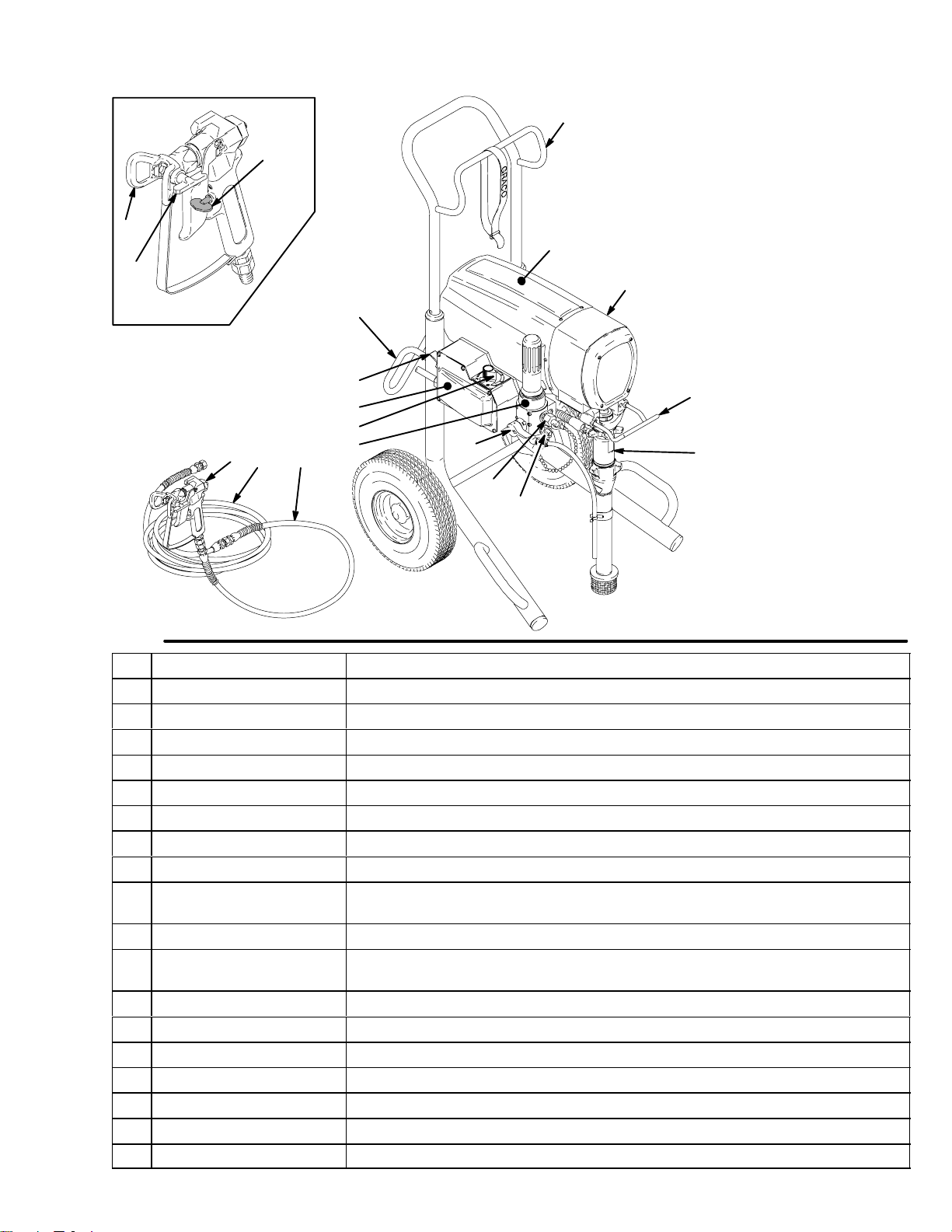
Component Identification and Function
V
T
S
R
03008
N
P
Fig. 1
A Motor DC motor, permanent magnet, totally enclosed, fan cooled
B Drive Assembly Transfers power from DC motor to the displacement pump
C Pail Hanger Container for fluid to be sprayed may be hung here
D Displacement Pump Transfers fluid to be sprayed from source through spray gun
E Primary Fluid Outlet Single spray gun operation is connected here
F Secondary Fluid Outlet Second spray gun operation is connected here
G Pressure Drain Valve Relieves fluid outlet pressure when open
H Fluid Filter Final filter of fluid between source and spray gun
J Pressure Adjusting Knob Controls fluid outlet pressure
K Pressure Control Controls motor speed to maintain fluid outlet pressure at displacement pump
L ON/OFF Switch Power switch that controls 120 VAC main power to sprayer
M 3 ft (0.9 m) Hose 3/16 in. ID, grounded, nylon hose used between 50 ft hose and spray gun to
N 50 ft (15 m) Main Hose 1/4 in. ID, grounded, nylon hose with spring guards on both ends
P Contractor Gun High pressure spray gun with gun safety latch
R RAC IV Switch Tip Uses high pressure fluid to clear tip clogs without removing tip from spray gun
S RAC IV Tip Guard Reverse-A-Clean (RAC) tip guard reduces the risk of injection injury
T Spray Gun Safety Latch Gun safety latch inhibits accidental triggering of spray gun
U Power Cord Rack Holds wrapped power cord for storage
V Spray Hose Rack Holds wrapped spray hose for storage
M
U
L
K
J
H
outlet. Works with pressure adjusting knob.
allow more flexibility when spraying
G
F
A
B
C
D
E
7706A
5308800
Page 6
Setup
WARNING
If you supply your own hoses and spray gun, be
sure the hoses are electrically conductive, that the
gun has a tip guard, and that each part is rated for
at least 3000 psi (210 bar, 21 MPa) Working Pres-
sure. This is to reduce the risk of serious injury
caused by static sparking, fluid injection or overpressurization and rupture of the hose or gun.
CAUTION
To avoid damaging the pressure control, which may
result in poor equipment performance and component damage, follow these precautions:
Do not allow material to freeze in sprayer.
Use nylon spray hose at least 50 ft (15 m) long.
Do not use wire braid hose.
2. Single gun hookup.
Use 1/4 in. ID, 50 ft (minimum) main hose. For
more flexible gun movement, install 3/16 in. ID, 3
ft hose between main hose and gun.
a. Connect gun, 3 ft hose and 50 ft hose.
b. Connect gun and hose assembly to primary
fluid outlet (F). Do not use thread sealant.
c. Do not install spray tip.
3. Two gun hookup.
Use 1/4 in. ID, 50 ft (minimum) main hose. For
more flexible gun movement, install 3/16 in. ID, 3
ft hose between main hose and gun.
a. Connect gun, 3 ft hose and 50 ft hose.
b. Unscrew cap from 1/4 npsm(m) secondary
fluid outlet (E).
Do not install shutoff device between sprayer and
gun. See Fig. 1.
NOTE: See Fig. 1, except where noted.
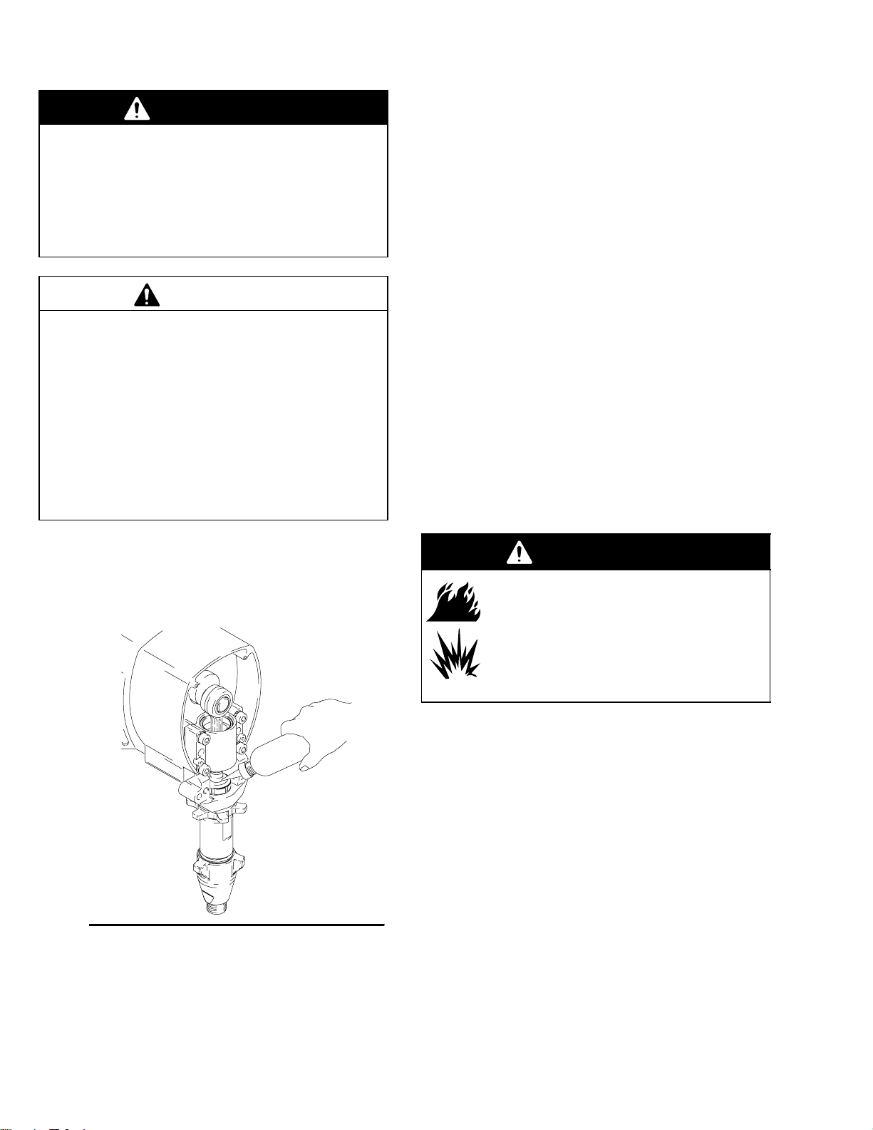
1. Fill packing nut full with Graco Throat Seal Liquid
(TSL), supplied. Fig. 2.
Fig. 2
7677A
c. Connect gun and hose assembly to secondary
fluid outlet.
WARNING
FIRE AND EXPLOSION HAZARD
Proper electrical grounding is essential
to reduce the risk of fire or explosion
which can result in serious injury and
property damage. Also read FIRE OR
EXPLOSION HAZARD on page 4 and
Grounding, page 7.
4. Turn ON/OFF (L) switch OFF. Plug sprayer power
cord into grounded electrical outlet at least 20 ft
(6 m) from spray area.
5. Flush pump to remove oil. See Flushing,
page 10.
6. Prepare paint according to manufacturer’s recommendations. Remove any paint skin. Stir paint
thoroughly. Strain paint through fine nylon mesh
bag (available at most paint dealers) to remove
particles that could clog filter or spray tip. This is
an important step for trouble-free paint spraying.
6 308800
Page 7

Grounding
Setup
Grounded
Outlets
WARNING
Improper installation or alteration of the grounding
plug will result in a risk of electric shock, fire or
explosion that could cause serious injury or death.
1. This equipment requires a 120 VAC, 60 Hz, 15A
circuit with a grounding receptacle. See Fig. 3.
Startup
WARNING
INJECTION HAZARD
The system pressure must be manually
relieved to prevent the system from
starting or spraying accidentally. Fluid
under high pressure can be injected through the
skin and cause serious injury. To reduce the risk of
an injury from injection, splashing fluid, or moving
parts, follow the Pressure Relief Procedure
whenever you:
are instructed to relieve the pressure,
stop spraying,
check or service any of the system equipment,
or install or clean the spray tip.
Pressure Relief Procedure
1. Engage gun safety latch.
2. Turn ON/OFF switch to OFF.
3. Unplug power supply cord.
4. Disengage gun safety latch. Hold metal part of gun
firmly to grounded metal pail. Trigger gun to relieve
pressure.
5. Engage gun safety latch.
6. Open pressure drain valve. Leave pressure drain
valve open until ready to spray again.
If you suspect that the spray tip or hose is completely
clogged, or that pressure has not been fully relieved
after following the steps above, VERY SLOWLY loos-
en tip guard retaining nut or hose end coupling to
relieve pressure gradually, then loosen completely.
Now clear tip or hose obstruction.
Fig. 3
Grounding Prong
2. Do not alter ground prong or use adapter.
3. A 12 AWG, 3 wires with grounding prong, 300 ft
(90 m) extension cord may be used. Long lengths
reduce sprayer performance.
NOTE: See Fig. 4 except where noted.
4. Put suction tube (39) into paint container.
5. Turn pressure adjusting knob (J) fully counterclockwise to zero pressure.
6. Plug in sprayer power cord.
CAUTION
Do not run pump without fluid in it for more than 30
seconds to avoid damaging pump packings.
WARNING
FIRE AND EXPLOSION HAZARD
To reduce risk of static sparking and
splashing when priming or flushing
system, hold metal part of gun firmly to
side of grounded metal pail before triggering gun.
7. Prime pump.
a. Open (handle down) pressure drain valve (G).
If no secondary hose is installed, be sure secondary outlet cap is installed. Turn ON/OFF
(L) switch ON. Slowly turn pressure adjusting
knob clockwise until sprayer starts. When fluid
comes from drain hose, close pressure drain
valve (handle forward).
b. Fig. 5. Disengage gun safety latch. Following
warning, above, trigger gun until all air is
forced out of system and paint flows freely
from gun.
Use this procedure each time you start sprayer to ensure sprayer is ready to operate safely.
Startup Procedure
NOTE: Flush sprayer if first-time startup.
See page 10.
c. Release trigger. Engage gun safety latch.
8. Check all fluid connections for leaks. Relieve fluid
pressure before tightening connections.
9. Fig. 5. Engage gun safety latch. Install spray tip.
Install tip guard. See manual 308644, supplied.
7308800
Page 8

Startup
10. Adjust spray pattern.
a. Increase pressure just until spray from gun is
completely atomized. Use lowest pressure
necessary to get desired results. This reduces
overspray and fogging, decreases tip wear and
extends the life of the sprayer.
b. For more coverage, use larger tip rather than
increasing pressure.
c. Test spray pattern. To adjust pattern, engage
gun safety latch, loosen retaining nut. Position
tip guard horizontally for horizontal pattern or
vertically for vertical pattern. Then tighten
retaining nut. Fig. 5.
RAC IV
HANDLE
Fig. 5
RETAINING
NUT
GUN SAFETY
LATCH ENGAGED
GUN SAFETY
LATCH DISENGAGED
Cleaning a Clogged Tip
WARNING
INJECTION HAZARD
To reduce the risk of serious injury,
whenever you are instructed to relieve
pressure, follow the Pressure Relief
Procedure on page 7.
03008
L
Fig. 4
1. Relieve pressure.
2. Clean front of tip frequently during operation.
3. If spray tip clogs, release gun trigger, engage gun
safety latch, and rotate RAC IV handle 180.
See Fig. 5.
J
G
F
E
39
7691A
4. Disengage gun safety latch and trigger gun into
waste container. Engage gun safety latch again.
5. Rotate RAC IV handle 180 to original position,
disengage gun safety latch, and resume spraying.
6. If tip is still clogged, engage gun safety latch, shut
off and unplug the sprayer, and open pressure
drain valve to relieve pressure. Clean spray tip as
shown in manual 308644.
8 308800
Page 9
Shutdown and Care
WARNING
INJECTION HAZARD
To reduce the risk of serious injury,
whenever you are instructed to relieve
pressure, follow the Pressure Relief
Procedure on page 7.
1. Check packing nut (A) daily. First relieve pressure.
Keep packing nut full of TSL at all times to help
prevent fluid buildup on piston rod and premature
wear of packings.
If pump begins to leak, loosen packing nut and
remove throat nut spacer (228). Tighten packing
nut just snug. Over tightening causes binding and
excessive packing wear. Use a round punch or
brass rod and light hammer to adjust nut. Refer to
Fig. 6. When leakage occurs again, repack the
pump.
6. Coil hose and hang it on hose rack when storing it,
even for overnight, to help protect hose from kinking, abrasion, coupling damage, etc.
A
228
TIGHTEN
2. Clean fluid filter often and whenever sprayer is
stored. Follow Flushing Guidelines on page 10 for
cleaning procedure.
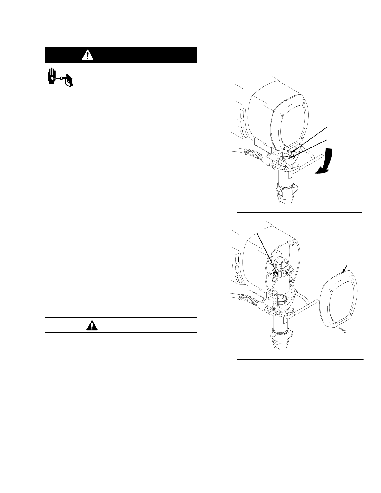
3. Lubricate bearing housing after every 100 hours of
operation. First relieve pressure. Remove front
cover (49). Fill bearing housing cavity (B) with SAE
10 non-detergent oil. See Fig. 7.
4. For very short shutoff periods, leave suction tube
in paint, relieve pressure, and clean spray tip.
5. Flush sprayer at end of each work day and fill it
with mineral spirits to help prevent pump corrosion
and freezing. See page 10.
CAUTION
To prevent pump corrosion, never leave water or any
type of paint in the sprayer when it is not in use.
Pump water or paint out with mineral spirits.
Fig. 6
Fig. 7
7692A
B
49
7693A
9308800
Page 10
Flushing
When to flush
Determine material to spray from column 1. Flush with
material in column 2. Then follow recommendations in
one of next three columns.
If you are going to: Flush with: Prime with: Clean with: Store unit with:
Do not leave water or water-based fluids in sprayer if
it could freeze. Push water out with mineral spirits.
Frozen fluid in sprayer prevents starting and may
cause serious damage.
CAUTION
Spray with new sprayer or
sprayer that has been
stored
Spray latex paint Warm, soapy water,
Spray oil paint Mineral spirits Oil-base paint Mineral spirits Mineral spirits
Change latex to oil paint Warm, soapy water,
Change oil to latex paint Mineral spirits, then
Change colors, same base Compatible solvent
Mineral spirits, then
compatible solvent
such as water or
mineral spirits
then clean water
then clean water
soapy water, and finally, clean water
such as water or
mineral spirits
Compatible paint,
such as latex or
oil-base
Latex paint Warm soapy water,
Mineral spirits Mineral spirits Mineral spirits
Latex Warm, soapy water,
Compatible solvent
such as water or
mineral spirits
then clean water
then clean water
Mineral spirits
Mineral spirits
Mineral spirits
How to flush
6. Do not run pump dry for more than 30 seconds to
WARNING
FIRE AND EXPLOSION HAZARD
To reduce static sparking and splashing,
always remove the spray tip from the
gun, and hold a metal part of the gun
firmly to the side of a grounded metal pail when
flushing.
1. Follow Pressure Relief Procedure on page 7.
Engage gun safety latch.
2. Turn pressure adjusting knob (J) fully counterclockwise to zero pressure.
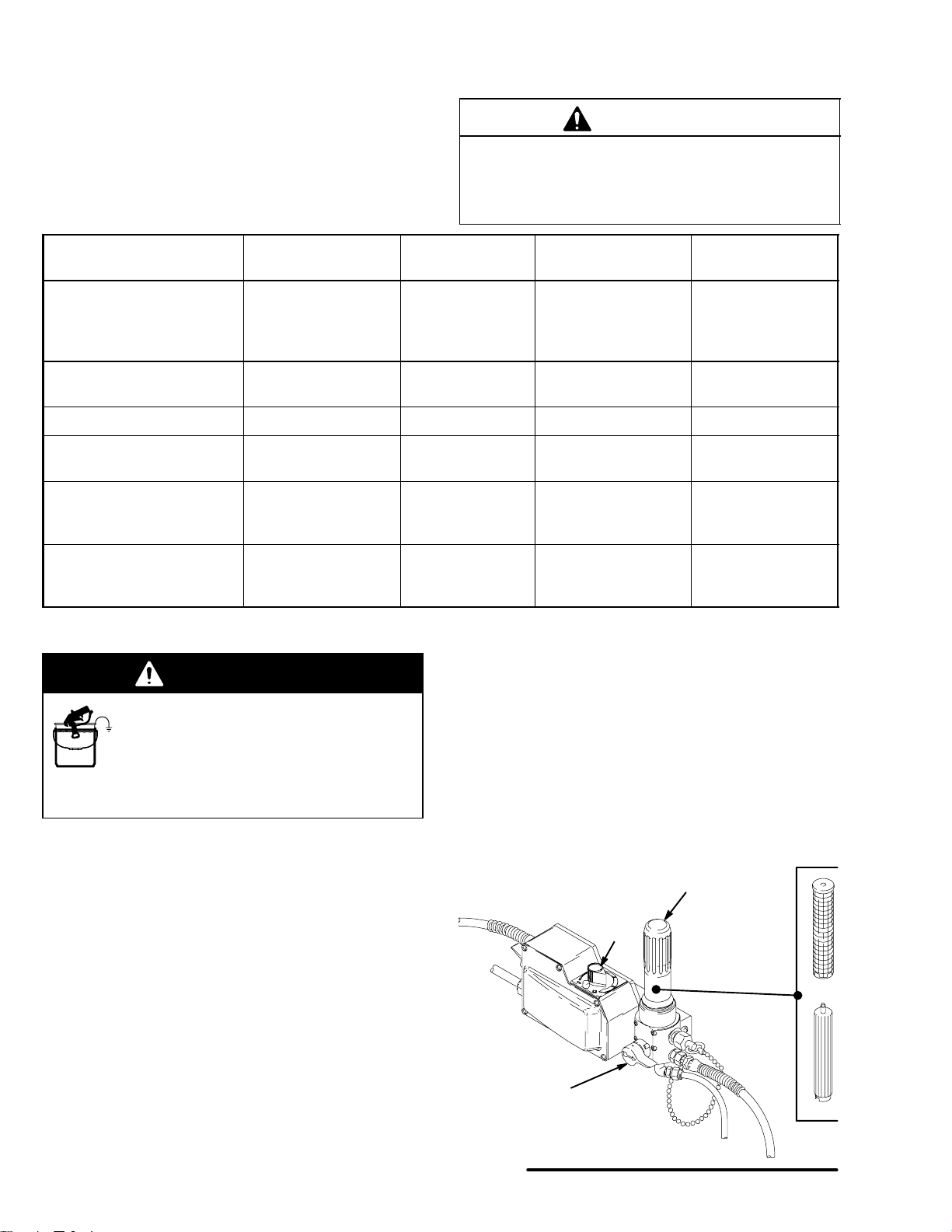
3. Remove spray tip from gun. See Fig. 8. Remove
filter bowl, filter support and screen. Clean screen
separately and install bowl without screen or
support to flush it.
avoid damaging pump packings!
7. Follow Pressure Relief Procedure on page 7.
Engage gun safety latch.
8. Unscrew filter bowl and reinstall clean screen.
Install bowl and hand tighten.
9. Remove suction tube and screen and clean them
separately.
FILTER
BOWL
J
SCREEN
4. Put suction tube into a grounded metal pail with
1/2 gallon of compatible solvent. Close pressure
drain valve (G).
5. Start sprayer. See page 7. To save fluid still in
sprayer, trigger gun into another container until
next fluid appears, then trigger gun back into fluid
compatible solvent container. Circulate flushing
fluid a few minutes to thoroughly clean system.
10 308800
Fig. 8
FILTER
SUPPORT
G
7694A
Page 11

INJECTION HAZARD
To reduce the risk of serious injury, whenever you are instructed to relieve pressure, follow the Pressure Relief Procedure on page 7.
MOTOR WON’T OPERATE
Troubleshooting
WARNING
TYPE OF PROBLEM
Basic Fluid Pressure Problems
Basic Mechanical Problems 1. Check for frozen or hardened paint in pump
Basic Electrical Problems
WHAT TO CHECK
If check is OK, go to next check
1. Check pressure control knob setting. The motor will not run if it is at the minimum setting
(fully counterclockwise).
2. Check for a clogged spray tip or fluid filter. Refer to separate gun, tip, or fluid filter instruction
manual.
(64). Using a screwdriver, carefully try to rotate
fan at back of motor by hand. See page 17.
2. Check displacement pump connecting rod pin
(66). It must be completely pushed into connecting rod (63) and retaining spring (68) must
be firmly in groove of connecting rod. See Fig.
25.
3. Check for motor damage. Remove drive
housing assembly (67). See page 25. Try to
rotate fan by hand.
1. Check pressure control safety circuit. 2. Turn pressure control ON/OFF switch to
2. Check electrical supply with volt meter. Meter
must read 105–125 VAC.
WHAT TO DO
When check is not OK refer to this column
1. Slowly increase pressure setting to see if
motor starts.
2. Relieve pressure, refer to separate gun, tip,
or fluid filter instruction manual for cleaning.
1. Thaw. Plug in sprayer and turn on. Slowly
increase pressure setting to see if motor
starts. If it doesn’t, see NOTE 1, below.
2. Push pin into place and secure with spring
retainer.
3. Replace motor (73) if fan won’t turn. See
page 27.
OFF to RESET. If pressure control safety
continues to trip, see ELECTRICAL
SHORT on page 15.
2. Reset building circuit breaker; replace
building fuse. Try another outlet.
3. Check extension cord for damage. Check extension cord continuity with a volt meter.
4. Check sprayer power supply cord (79) for
damage such as broken insulation or wires.
NOTE 1: Thaw sprayer if water or water-based paint has frozen in it, due to exposure to low temperatures, by placing it in a warm
area. Do not try to start sprayer until it has thawed completely. If paint hardened (dried) in sprayer, pump packings must be replaced.
See page 29 (Displacement Pump Repair).
3. Replace extension cord.
4. Replace power supply cord. See page 19.
11308800
Page 12

Troubleshooting
MOTOR WON’T OPERATE (Continued)
TYPE OF PROBLEM
Basic Electrical Problems
(continued)
Follow Pressure Relief Pro-
cedure on page 7. Remove
gun from hose. Remove pressure control cover.
WHAT TO CHECK
If check is OK, go to next check
1. Check leads from motor to be sure they are
securely fastened and properly mated.
2. Check for loose motor brush lead connections
and terminals. See page 18.
3. Check brush length which must be 1/2 in. minimum. See page 18.
NOTE: The brushes do not wear at the same
rate on both sides of the motor. Check both
brushes.
4. Check for broken or misaligned motor brush
springs. Rolled portion of spring must rest
squarely on top of brush. See page 18.
5. Check motor brushes for binding in brush
holders. See page 18.
6. Check motor armature commutator for burn
spots, gouges and extreme roughness.
See page 18.
WHAT TO DO
When check is not OK refer to this column
1. Replace loose terminals; crimp to leads. Be
sure terminals are firmly connected.
Clean circuit board terminals. Securely reconnect leads.
2. Tighten terminal screws. Replace brushes
if leads are damaged. See page 18.
3. Replace brushes. See page 18.
4. Replace spring if broken. Realign spring
with brush. See page 18.
5. Clean brush holders. Remove carbon with
small cleaning brush. Align brush leads
with slot in brush holder to assure free vertical brush movement.
6. Remove motor and have motor shop resurface commutator if possible. See page 27.
Refer to wiring diagram on
page 35 to identify test points
(TP).
7. Check motor armature for shorts using armature tester (growler) or perform spin test. See
page 17.
8. Check motor control board (104) by performing motor control board diagnostics on page
21. If diagnostics indicate, substitute with a
good board.
CAUTION: Do not perform this check until
motor armature is determined to be good. A
bad motor armature can burn out a good
board.
1. Check power supply cord (79). Connect volt
meter between TP1 (neutral) and TP2. Plug in
sprayer. Meter must read 105 to 125 VAC. Unplug sprayer.
2. Check ON/OFF switch (80). Connect volt meter between TP1 and TP3 terminal on ON/
OFF switch. Plug in sprayer and turn ON. Meter must read 105 to 125 VAC. Turn off and unplug sprayer. Reconnect TP3.
3. Check motor thermal cutoff switch. Turn
sprayer OFF. Check for continuity between
TP4 and TP5 with ohmmeter.
4. Check all terminals for damage or loose fit. 4. Replace damaged terminals and recon-
7. Replace motor. See page 27.
8. Replace with new pressure control board
(104). See page 21.
1. Replace power supply cord. See page 19.
2. Replace ON/OFF switch. See page 19.
3. If thermal switch is open (no continuity), allow motor to cool. If switch remains open after motor cools, replace motor. If thermal
switch closes after motor cools, correct
cause of overheating.
nect securely.
12 308800
Page 13

LOW OUTPUT
Troubleshooting
TYPE OF PROBLEM
Low Output
WHAT TO CHECK
If check is OK, go to next check
1. Check for worn spray tip. 1. Follow Pressure Relief Procedure Warn-
2. Check to see that pump does not continue to
stroke when gun trigger is released. Plug in
and turn on sprayer. Prime with paint. Trigger
gun momentarily, then release and engage
safety latch. Relieve pressure, turn off and unplug sprayer.
3. Check electrical supply with volt meter. Meter
must read 105–125 VAC.
4. Check extension cord size and length; must
be at least 12 gauge wire and no longer than
300 ft.
5. Check leads from motor to pressure control
circuit board (104) for damaged or loose wires
or connectors. Inspect wiring insulation and
terminals for signs of overheating.
6. Check for loose motor brush leads and terminals. See page 18.
7. Check for worn motor brushes which must be
1/2 in. minimum. See page 18.
WHAT TO DO
When check is not OK refer to this column
ing, then replace tip. See your separate
gun or tip manual.
2. Service pump. See page 29.
3. Reset building circuit breaker; replace
building fuse. Repair electrical outlet or try
another outlet.
4. Replace with a correct, grounded extension cord.
5. Be sure male terminal blades are centered
and firmly connected to female terminals.
Replace any loose terminal or damaged
wiring. Securely reconnect terminals.
6. Tighten terminal screws. Replace brushes
if leads are damaged. See page 18.
7. Replace brushes. See page 18.
8. Check for broken and misaligned motor brush
springs. Rolled portion of spring must rest
squarely on top of brush.
9. Check motor brushes for binding in brush
holders. See page 18.
10.Check stall pressure. 10.Replace with new pressure control board
11.Check motor armature for shorts by using an
armature tester (growler) or perform spin test.
See page 17.
12.Check motor control board (104) by performing motor control board diagnostics on page
21. If diagnostics indicate, substitute with a
good board.
CAUTION: Do not perform this check until
motor armature is determined to be good. A
bad motor armature can burn out a good
board.
8. Replace spring if broken. Realign spring
with brush. See page 18.
9. Clean brush holders, remove carbon dust
with small cleaning brush. Align brush lead
with slot in brush holder to assure free vertical brush movement.
(104). See page 21.
12.Replace motor. See page 27.
11. Replace with new pressure control board
(104). See page 21.
13308800
Page 14

NO OUTPUT
Troubleshooting
TYPE OF PROBLEM
Motor runs and pump strokes 1. Check paint supply. 1. Refill and reprime pump.
Motor runs but pump does not
stroke
WHAT TO CHECK
If check is OK, go to next check
2. Check for clogged intake strainer. 2. Remove and clean, then reinstall.
3. Check for loose suction tube or fittings. 3. Tighten; use thread sealant or sealing tape
4. Check to see if intake valve ball and piston ball
are seating properly. See page 29.
5. Check for leaking around throat packing nut
which may indicate worn or damaged packings. See page 29.
1. Check displacement pump connecting rod pin
(66). See page 30.
2. Check connecting rod assembly (63) for damage. See page 24.
3. Be sure crank in drive housing rotates; plug in
sprayer and turn on briefly to check. Turn off
and unplug sprayer. See page 25.
WHAT TO DO
When check is not OK refer to this column
on threads if necessary.
4. Remove intake valve and clean. Check
balls and seats for nicks; replace if necessary. See page 29. Strain paint before using to remove particles that could clog
pump.
5. Replace packings. See pages 29–30. Also
check piston valve seat for hardened paint
or nicks and replace if necessary. Tighten
packing nut/wet-cup.
1. Replace pin if missing. Be sure retainer
spring (68) is fully in groove all around connecting rod. See page 30.
2. Replace connecting rod assembly. See
page 24.
3. Check drive housing assembly for damage
and replace if necessary. See page 25.
EXCESSIVE PRESSURE FLUCTUATIONS
TYPE OF PROBLEM
Spray pattern variations. 1. Be sure leads to motor control board are firmly
WHAT TO CHECK
If check is OK, go to next check
connected. Be sure all male terminals blades
are centered and firmly connected to female
terminals. See Fig. 29.
2. Check maximum working pressure. 2. Replace pressure control board (104).
3. Check motor control board (104) by performing motor control board diagnostics on page
21. If diagnostics indicate, substitute with a
good board.
CAUTION: Do not perform this check until
motor armature is determined to be good. A
bad motor armature can burn out a good
board.
4. Check LOW OUTPUT section, page 13.
WHAT TO DO
When check is not OK refer to this column
1. Reconnect securely. See Fig. 29.
See page 21.
3. Replace with a new pressure control board
(104). See page 21.
14 308800
Page 15

Troubleshooting
MOTOR IS HOT AND RUNS INTERMITTENTLY
TYPE OF PROBLEM
Motor is hot and runs intermittently.
ELECTRICAL SHORT
TYPE OF PROBLEM
Building circuit breaker opens
as soon as sprayer switch is
turned on.
CAUTION
Any short in any part of the
motor power circuit will cause
the control circuit to inhibit
sprayer operation. Correctly
diagnose and repair all shorts
before checking and replacing control board.
WHAT TO CHECK
If check is OK, go to next check
1. Determine if sprayer was operated at high
pressure with small tips, which causes low
motor RPM and excessive heat build up.
2. Be sure ambient temperature where sprayer
is located is no more than 90
is not located in direct sun.
3. Determine if sprayer was turned on, pressurized, but not operating for long periods of time.
WHAT TO CHECK
If check is OK, go to next check
1. Check all electrical wiring for damaged insulation, and all terminals for loose fit or damage.
Also check wires between pressure control
and motor. See page 27.
2. Check for missing inspection plate gasket
(see page 27), bent terminal forks or other
metal to metal contact points which could
cause a short.
3. Check motor armature for shorts. Use an armature tester (growler) or perform spin test.
See page 17. Inspect windings for burns.
F and sprayer
WHAT TO DO
When check is not OK refer to this column
1. Decrease pressure setting or increase tip
size.
2. Move sprayer to shaded, cooler area if possible.
3 Turn off sprayer whenever you stop spray-
ing for a while and relieve fluid pressure.
WHAT TO DO
When check is not OK refer to this column
1. Repair or replace any damaged wiring or
terminals. Securely reconnect all wires.
2. Correct faulty conditions.
3. Replace motor. See page 27.
Building circuit breaker opens
as soon as sprayer is plugged
into outlet and sprayer is NOT
turned on.
Sprayer quits after sprayer operates for 5 to 10 minutes.
.
4. Check motor control board (104) by performing motor control board diagnostics on page
21. If diagnostics indicate, substitute with a
good board.
CAUTION: Do not perform this check until
motor armature is determined to be good. A
bad motor armature can burn out a good
board.
1. Check Basic Electrical Problems on page 11. 1. Perform necessary procedures.
2. Check ON/OFF switch (80) See page 19. Be
sure sprayer is unplugged! Disconnect wires
from switch. Check switch with ohmmeter.
The reading must be infinity with the ON/OFF
switch OFF, and zero with the switch ON.
3. Check for damaged or pinched wires in the
pressure control. See page 21.
1. Check Basic Electrical Problems on page 11. 1. Perform necessary procedures.
2. Check electrical supply with volt meter. Meter
must read 105 to 125 VAC.
3. Check tightness of pump packing nut. Over
tightening tightens packings on rod, restricts
pump action, and damages packings.
4. Replace with a new pressure control board
(104). See page 21.
2. Replace ON/OFF switch. See page 19.
3. Replace damaged parts. See page 21.
2. If voltage is too high, do not operate
sprayer until corrected.
3. Loosen packing nut. Check for leaking
around throat. Replace pump packings, if
necessary. See page 29.
15308800
Page 16

General Repair Information
CAUTION
To reduce the risk of a pressure control malfunction:
Always use needle nose pliers to disconnect a
wire. Never pull on the wire, pull on the connector.
Mate wire connectors properly. Be sure flat blade
of insulated male connector is centered in wraparound blade of female connector.
Route wires carefully to avoid interference with
other connections of pressure control. Be sure
wires are not pinched between cover and control
box.
Tool List
Phillips screwdriver
Small flat blade
screwdriver
Needle nose pliers
Plastic mallet or 20 oz
(max) hammer
12 in. adjustable wrench
Adjustable, open-end
wrench
Torque wrench
1/4 in. hex key wrench
3/16 in. hex key wrench
5/8 in. socket wrench
3/8 in. open end wrench
1/2 in. open end wrench
3/4 in. open end wrench
7/8 in. open end wrench
High quality motor oil
Bearing grease
WARNING
ELECTRIC SHOCK HAZARD
To reduce the risk of serious injury,
including electric shock, DO NOT touch
any moving parts or electrical parts with
your fingers or a tool while inspecting the repair.
Shut off the sprayer and unplug it as soon as you
complete the inspection. Reinstall all covers,
gaskets, screws and washers before operating the
sprayer.
3. If sprayer does not operate properly, review
repair procedure again to verify that everything
was done correctly. If necessary, see Troubleshooting Guide, pages 11 – 15, to help identify
other possible problems and solutions.
WARNING
EXPLOSION HAZARD
During operation, the motor and drive
housing become very hot and could burn
your skin if touched. Flammable materials spilled on the hot, bare motor could cause a fire
or explosion. Always have the motor shield in place
during regular operation to reduce the risk of burns,
fire or explosion.
1. Keep all screws, nuts, washers, gaskets, and
electrical fittings removed during repair procedures. These parts are not normally provided with
replacement assemblies.
2. Test repair before regular operation of sprayer
to be sure problem is corrected.
CAUTION
Do not run the sprayer dry for more than 30 seconds
to avoid damaging the pump packings.
4. Reinstall motor shield before regular operation
of sprayer and replace if damaged. The cover
directs cooling air around the motor to help prevent
overheating. It can also help reduce the risk of
burns, fire or explosion; see preceding WARNING.
16 308800
Page 17

WARNING
Spin Test
Armature, Brushes, and Motor Wiring Open
Circuit Test (Continuity)
ELECTRIC SHOCK HAZARD
Do not touch brushes, leads, springs or
brush holders while the sprayer is
plugged in to reduce risk of electric
shock and serious bodily injury.
WARNING
INJECTION HAZARD
To reduce the risk of serious injury,
whenever you are instructed to relieve
pressure, follow the Pressure Relief
Procedure on page 7.
For checking armature, motor winding and brush electrical continuity.
Setup
1. Relieve pressure. Remove drive housing. See
page 25.
2. Remove motor shield (54), fan cover (A) and
inspection covers (82). See Fig. 9.
3. Remove pressure control cover (B). Disconnect
motor leads (F) and (G). See Fig. 10.
Armature Short Circuit Test
Relieve pressure. Quickly turn motor fan by hand. If
there are no shorts, the motor will coast two or three
revolutions before coming to a complete stop. If the
motor does not spin freely, the armature is shorted and
the motor must be replaced. See page 27.
1. Relieve pressure. Connect red and black motor
leads together with a test lead. Turn motor fan by
hand at about two revolutions per second.
2. If there is uneven or no turning resistance, check
following: broken brush springs, brush leads,
motor leads; loose brush terminal screws, motor
lead terminals; worn brushes. Repair parts as
needed. See page 18.
3. If there is still uneven or no turning resistance,
replace motor. See page 27.
F
G82
Fig. 10
7695A
54
Fig. 9
A
B
7703B
17308800
Page 18

Motor Brush Replacement
NOTE: Replace brushes worn to less than 1/2 in. Note
that brushes wear differently on each side of motor, so check both. Brush Repair Kit 220853 is
available. A new spring clip, 110816, may be
purchased separately.
WARNING
INJECTION HAZARD
To reduce the risk of serious injury,
whenever you are instructed to relieve
pressure, follow the Pressure Relief
Procedure on page 7.
NOTE: Read General Repair Information on page 16
before doing this procedure.
1. Relieve pressure.
2. Remove motor shield (54). Remove inspection
covers (B) and gaskets on each side of motor.
See Fig. 11.
5. Inspect commutator for excessive pitting, burning
or gouging. A black color on commutator is normal.
Have commutator resurfaced by a qualified motor
repair shop if brushes seem to wear too fast.
CAUTION
When installing the brushes, follow all steps carefully
to avoid damaging the parts.
6. Install new brush so lead is in long slot of holder.
See Fig. 13.
BRUSH HOLDER
SHORT SLOT
LONG SLOT
BRUSH
SPRING
CLIP
54
Fig. 11
B
3. Push in spring clip to release hooks from brush
holder. Pull out spring clip. See Fig. 12.
SPRING
HOOK
BRUSH
SPRING CLIP
110–816
Fig. 12
7703B
01227
Fig. 13
NOTE: SPRING MUST COIL
IN THIS DIRECTION
01227
7. Slide terminal under terminal screw washer and
tighten screw. Be sure motor lead is still connected
at screw. See Fig. 14.
SPRING
BRUSH
Fig. 14
TERMINAL SCREW
MOTOR LEAD
TERMINAL
SPRING CLIP
BRUSH LEAD
8. Place spring on brush as shown in Fig. 13.
01227
4. Loosen brush lead terminal screw. Pull brush lead
away, leaving motor lead terminal in place. Remove brush and spring. See Fig. 14.
18 308800
9. Install spring clip and push it down to hook short
slots in housing. See Fig. 13.
10. Repeat for other side.
Page 19

Motor Brush Replacement
11. Test brushes.
a. Remove pump connecting rod pin.
b. With sprayer OFF, turn pressure control knob
fully counterclockwise to minimum pressure.
Plug in sprayer.
c. Turn sprayer ON. Slowly increase pressure
until motor is at full speed.
d. Inspect brush and commutator contact area for
excessive arcing. Arcs must not trail or circle
around commutator surface.
CAUTION
Do not run the sprayer dry for more than 30 seconds
while checking the brushes to avoid damaging the
displacement pump packings.
12. Install brush inspection covers and gaskets.
13. Break in brushes.
WARNING
ELECTRIC SHOCK HAZARD
Do not touch brushes, leads, springs or
brush holders when sprayer is plugged
in to reduce risk of electric shock and
serious bodily injury.
Power Supply Cord
Replacement
WARNING
INJECTION HAZARD
To reduce the risk of serious injury,
whenever you are instructed to relieve
pressure, follow the Pressure Relief
Procedure on page 7.
NOTE: Read General Repair Information on page 16
before doing this procedure. See Fig. 15.
1. Relieve pressure.
2. Remove pressure control cover (82).
3. Disconnect power supply cord black (J) lead from
ON/OFF switch (80),the white wire (D) going to
circuit board, and green wire (E) to grounding
screw (107).
a. Operate sprayer for one hour with no load.
b. Install connecting rod pin.
On/Off Switch
Replacement
WARNING
INJECTION HAZARD
To reduce the risk of serious injury,
whenever you are instructed to relieve
pressure, follow the Pressure Relief
Procedure on page 7.
NOTE: Read General Repair Information on page 16
before doing this procedure. See Fig. 15.
1. Relieve pressure.
2. Remove pressure control cover (82).
3. Disconnect two wires (B) and (J) from ON/OFF
switch (80).
4. Loosen strain relief bushing (G) and remove power
supply cord (79).
5. Install power supply cord (79) and tighten strain
relief bushing (G).
6. Connect power supply cord black (J) lead to
ON/OFF switch (80), white wire to circuit board
(D), and green wire (E) to grounding screw (107).
7. Install pressure control cover (82).
4. Press in on two retaining tabs on each side of
ON/OFF switch (80) and remove.
5. Install new ON/OFF switch (80) so tabs of switch
snap into place on inside of pressure control
housing.
6. Connect two wires (B) and (J) to ON/OFF switch.
7. Install pressure control cover (82).
19308800
Page 20

Power Supply Cord and On/Off Switch
Replacement
B
80
J
Fig. 15
82
79 G
107 E
D
7696B
20 308800
Page 21

Pressure Control Repair
WARNING
Motor Control Board Installation
INJECTION HAZARD
To reduce the risk of serious injury,
whenever you are instructed to relieve
pressure, follow the Pressure Relief
Procedure on page 7.
Motor Control Board Removal
1. Relieve pressure.
2. Fig. 16. Remove five screws (28) and cover (82).
3. Disconnect from motor control board:
Six motor leads (B).
Lead (C) from power cord.
Lead (111) from ON/OFF switch.
Lead (D) from potentiometer.
Lead (E) from transducer.
4. Remove four screws (102), washers (103) and
circuit board (104).
1. Relieve pressure.
2. Fig. 16. Install motor control board (104) with four
screws (102) and washers (103).
3. Connect to motor control board:
Lead (E) to transducer.
Lead (D) to potentiometer.
Lead (111) to ON/OFF switch.
Lead (C) to power cord.
Six motor leads (B).
4. Install cover (82) with five screws (28).
Motor control board diagnostics
1. Relieve pressure.
2. Remove five screws (28) and cover (82).
See Fig. 16.
LED
BLINKS
Once Sprayer runs Normal operation Do nothing
Twice Sprayer runs Normal operation Do nothing
Twice
repeatedly
Three times
repeatedly
Four times
repeatedly
Five times
repeatedly
SPRAYER OPERATION INDICATES WHAT TO DO
Sprayer shuts down and LED continues
to blink twice repeatedly
Sprayer shuts down and LED continues
to blink three times repeatedly
Sprayer shuts down and LED continues
to blink four times repeatedly
Sprayer shuts down and LED continues
to blink five times repeatedly
3. Turn ON/OFF switch ON.
4. Observe LED operation and reference following
table:
Line voltage is too
high
Pressure transducer
is faulty or missing
Run away pressure.
Pressure greater than
4500 psi.
Locked rotor. Motor
can not turn because
of some mechanical
condition.
Lower line voltage to 120 VAC
Replace pressure transducer
Replace motor control board.
See preceding Motor control
board removal procedure.
Clear obstruction and replace
broken parts preventing motor
from turning
21308800
Page 22

Pressure Control Repair
Pressure Control Transducer Removal
1. Relieve pressure.
2. Fig. 16. Remove five screws (28) and cover (82).
3. Disconnect lead (E) from motor control
board (104).
4. Remove strain relief bushing (116).
5. Remove pressure control transducer (31) and
packing o-ring (59) from control housing plate (89).
Pressure Control Transducer Installation
1. Relieve pressure.
2. Fig. 16. Install packing o-ring (59) and pressure
control transducer (31) in control housing
plate (89). Torque to 30–35 ft-lb.
3. Install strain relief bushing (116).
4. Connect lead (E) to motor control board (104).
Pressure Adjust Potentiometer Removal
1. Relieve pressure.
2. Fig. 16. Remove five screws (28) and cover (82).
3. Disconnect lead (D) from motor control
board (104).
4. Remove potentiometer knob (81), sealing shaft nut
(106) and pressure adjust potentiometer (105).
Pressure Adjust Potentiometer Installation
1. Relieve pressure.
2. Fig. 16. Install pressure adjust potentiometer
(105), sealing shaft nut (106) and potentiometer
knob (81).
3. Connect lead (D) to motor control board (104).
5. Install cover (82) with five screws (28).
4. Install cover (82) with five screws (28).
22 308800
Page 23

98
112
Pressure Control Repair
59 31
97
116
81
89
99
28
82
107 A
104
102
87
91
86
120
50
B
111
E
Fig. 16
D
C
7697C
23308800
Page 24

Bearing Housing and Connecting Rod
Replacement
WARNING
INJECTION HAZARD
To reduce the risk of serious injury,
whenever you are instructed to relieve
pressure, follow the Pressure Relief
Procedure on page 7.
NOTE: Read General Repair Information on page 16
before doing this procedure. See Fig. 17.
NOTE: Stop sprayer at bottom of its stroke to get crank
(E) in its lowest position.To lower crank manually, carefully rotate blades of fan with a screwdriver.
1. Relieve pressure.
2. Remove front cover (49). Unclip drain hose (36)
from pump. Hold a wrench on pump intake valve
(213) and unscrew pump suction tube (39). Disconnect pump hose (70).
3. Push up retaining spring (68). Push pin (66) out
rear.
11. Align connecting rod (63) with crank (E) and drive
housing locating pins (G) with bearing housing (22)
holes. Push bearing housing onto drive housing or
tap it into place with a plastic mallet.
CAUTION
DO NOT use the bearing housing screws (25) to try
to align or seat the bearing housing; the bearing and
drive housing will not align properly and will result in
premature bearing wear.
12. Install screws and lockwashers (25,23). Tighten
screws evenly to 175 in-lb (19 N.m).
13. Install pump. See page 30.
14. Install remaining parts. See Fig. 17.
B
67
E
OIL
PACK WITH
C
BEARING GREASE
63
25,23
TORQUE TO
175 in-lb (19 N.m)
49
4. Loosen locknut (47). Unscrew displacement
pump (64).
5. Remove four screws and lockwashers (25,23).
6. Lightly tap lower rear of bearing housing (22) with
a plastic mallet to loosen it from drive housing (67).
Pull bearing housing and connecting rod assembly
(63) straight off drive housing.
7. Remove pail bracket assembly (F) and install it on
new bearing housing.
8. Inspect crank (E) for excessive wear and replace
parts as needed. Evenly lubricate inside of bronze
bearing (B) with high quality motor oil. Liberally
pack roller bearing (C) with bearing grease.
9. Assemble connecting rod (63) and bearing housing
(22).
10. Clean mating surfaces of bearing and drive housings (22,67).
70
Fig. 17
22
G
68
47
66
40
64
213
39
36
85
F
7698A
24 308800
Page 25

Drive Housing Replacement
WARNING
INJECTION HAZARD
To reduce the risk of serious injury,
whenever you are instructed to relieve
pressure, follow the Pressure Relief
Procedure on page 7.
CAUTION
DO NOT drop gear cluster (51) when removing drive
housing (67). Gear cluster may stay engaged in the
motor front end bell or the drive housing.
DO NOT lose thrust balls (90) located at each end of
gear cluster (51) or drop them between gears. The
balls, which are heavily covered with grease, usually
stay in the shaft recesses, but could be dislodged. If
caught between gears and not removed, the balls will
seriously damage drive housing. If the balls are not
in place, the bearings will wear prematurely.
NOTE: Read General Repair Information on page 16
before doing this procedure. See Fig. 18.
4. Lightly tap lower rear of bearing housing (22) with
a plastic mallet to loosen it from drive housing (67).
Pull assembled bearing housing and connecting
rod straight off drive housing.
5. Remove two drive housing screws (26) and
lockwashers (20).
6. Remove two lower screws (16) and lockwashers
(20) and then two upper screws (16) and lockwashers (20) from front of motor (73).
7. Tap drive housing (67) with a plastic mallet to
loosen it from front of motor (73), and then pull
drive housing straight off.
8. Liberally apply approximately 4 ounces of bearing
grease to gear cluster (51). Grease is supplied
with drive housing replacement kit. Be sure thrust
balls (90) are in place.
9. Place bronze-colored washer (67b) then silver-colored washer (67a) on shaft protruding from big
gear in drive housing (67).
1. Relieve pressure.
2. Remove front cover (49) and motor shield (54).
Unclip drain hose (85) from pump.
3. Remove four bearing housing screws (25) and
lockwashers (23).
10. Align gears and push new drive housing straight
onto front of motor and locating pins.
11. Continue reassembling sprayer.
25308800
Page 26

Drive Housing Replacement
34
16
2
20
54
16
2
20
Torque to 175 in-lb (19 N.m)
1
2
Torque to 90–100 in-lb (10.2–11.3 N.m)
3
Liberally apply grease
90
90
67a
51
3
67b
67
22
25,23
1
49
20
26
2
85
Fig. 18
26 308800
7699A
Page 27

Motor Replacement
WARNING
INJECTION HAZARD
To reduce the risk of serious injury,
whenever you are instructed to relieve
pressure, follow the Pressure Relief
Procedure on page 7.
NOTE: Read General Repair Information on page 16
before doing this procedure. See Fig. 16 and 19.
1. Relieve pressure.
2. Remove motor shield (54).
3. Remove pressure control cover (82). Disconnect
six motor leads (B). See figure 16.
CAUTION
Always pull the motor leads one at a time to avoid
loosening the terminals, which could result in a bad
connection and poor sprayer performance.
4. Remove strain relief (99) and pull motor wires
bundle through pressure control opening. See
figure 16.
5. Remove front cover (49).
CAUTION
DO NOT drop gear cluster (51) when removing drive
housing (67). The gear cluster may stay engaged in
the motor front end bell or the drive housing.
DO NOT lose thrust balls (90) located at each end of
gear cluster (51) or drop them between gears. The
balls, which are heavily covered with grease, usually
stay in the shaft recesses, but could be dislodged. If
caught between gears and not removed, the balls will
seriously damage the drive housing. If the balls are
not in place, the bearings will wear prematurely.
9. While supporting motor (73) to keep sprayer from
tipping, remove four motor mounting screws (8).
Lift off motor.
10. Install new motor (73).
11. Liberally apply approximately 4 ounces of bearing
grease to gear cluster (51). Grease is supplied
with drive housing replacement kit. Be sure thrust
balls (90) are in place.
12. Place bronze-colored washer (67b) and then
silver-colored washer (67a) on shaft protruding
from big gear in drive housing (67).
6. Remove two drive housing screws (26).
7. Remove two lower screws (16) and lockwashers
(20) and then two upper screws (16) and lockwashers (20) from front of motor (73).
8. Tap drive housing (67) with a plastic mallet to
loosen it from front of motor (73), and then pull
drive housing straight off.
13. Align gears and push drive housing (67) straight
onto front of motor (73) and locating pins.
14. Continue reassembling sprayer. Feed motor wires
through opening in pressure control. Connect six
motor leads to pressure control printed circuit
board. Install pressure control cover (A).
See Fig. 16.
27308800
Page 28

Motor Replacement
34
54
1
16
20
73
90
67a
51
2
67b
67
30
9879
A
1
Torque to 90–100 in-lb (10.2–11.3 N.m)
2
Liberally apply grease
Fig. 19
22
20
26
90
10
70
40
1
2016
85
49
7700B
28 308800
Page 29

Removing pump
Displacement Pump Repair
1. Flush pump. Relieve pressure. Fig. 20. Cycle
pump with piston rod (222) in its lowest position.
2. Fig. 20. Unscrew suction tube and hose from
pump.
222
Fig. 20
7672A
4. Fig. 22. Push out pin.
Fig. 22
5. Fig. 23. Loosen locknut by hitting firmly with a
20 oz (maximum) hammer. Unscrew pump.
7675A
3. Fig. 21. Use screwdriver to push retaining spring
up.
Fig. 21
7674A
Fig. 23
7673A
Repairing Pump
See manual 308798 for pump repair instructions.
29308800
Page 30

Displacement Pump Repair
Installing pump
WARNING
If the pin works loose, it or other parts could break
off due to the force of the pumping action. These
parts could be projected through the air and result
in serious bodily injury or property damage, including damage to the pump, connecting rod or bearing
housing.
CAUTION
If the pump locknut loosens during operation, the
threads of the bearing housing will be damaged.
3. Fig. 26. Push retaining spring into groove all the
way around connecting rod.
1. Fig. 24. Pull piston rod out 1.5 in. Screw in pump
until holes in bearing cross link and piston rod
align.
7676A
Fig. 24
2. Fig. 25. Push pin (21) into holes.
Fig. 26
Fig. 27. Screw jam nut down onto pump until stops.
Screw pump up into bearing housing until it is stopped
by jam nut. Back off pump and jam nut to align pump
outlet to back. Tighten jam nut by hand, then tap 1/8 to
1/4 turn with a 20 oz (maximum) hammer to approximately 75" 5 ft–lb (102 Nm).
Fig. 27
Fig. 28. Fill packing nut with Graco TSL, through one
of the slits, until fluid flows onto the top of seal.
7674A
7673A
Fig. 25
30 308800
7675A
21
Fig. 28
7677A
Page 31

Accessories
Technical Data
DANGER LABELS
The English language DANGER label shown on
page 4 is also on your sprayer. If you have painters who do not read English, order one of the following labels to apply to your sprayer. The drawing shows the best placement of these labels for
good visibility.
Order the labels directly from Graco, free of
charge. Toll Free: 1–800–328–0211
Apply other
language here
French 185955
Spanish 185962
German 186042
Greek 186046
Korean 186050
7691A
Power Requirements 120 VAC, 60 Hz,. . . . . . . . . . . . . . . . . . . .
Motor 1.0 HP. . . . . . . . . . . . . . . . . . . . . . . . . . . . . . . . . . . . . . . . .
Working Pressure Range 0–3000 psi (0–210 bar, 0–21 MPa)
Cycles/Gallon (liter) 244 (64.6). . . . . . . . . . . . . . . . . . . . . . . . . .
Maximum Delivery Rating 0.8 gpm (3 lpm). . . . . . . . . . . . . . . .
Tip Size one gun – 0.028; two guns – 0.019. . . . . . . . . . . . . . .
Power Cord 14 AWG, 3 wire, 15 ft (4.5 m). . . . . . . . . . . . . . . . .
Inlet Paint Strainer 16 mesh (975 micron). . . . . . . . . . . . . . . . .
Outlet Paint Filter 60 mesh (238 micron). . . . . . . . . . . . . . . . . .
Pump Inlet Size 3/4 npt(m). . . . . . . . . . . . . . . . . . . . . . . . . . . . .
Fluid Outlet Size
Filter 3/8 npt(f). . . . . . . . . . . . . . . . . . . . . . . . . . . . . . . . . . . . . .
Filter with standard 3/8 npt(f) to 1/4 npsm adapter 1/4 npsm
Basic Sprayer Wetted Parts: zinc-plated carbon steel,. . . . . .
NOTE: Delrin
1 phase, 15A minimum or 4000W generator
(with latex at 2000 psi (138 bar, 13.8 MPa)
(with latex at 2000 psi (138 bar, 13.8 MPa)
stainless steel screen, reusable
stainless steel screen, reusable
polyurethane, polyethylene, stainless steel,
PTFE, Delrin
is a registered trademark of the DuPont Co.
, chrome plating, leather,
V-Max UHMWPE, aluminum,
stainless steel, tungsten carbide
Dimensions
Weight (dry w/o packaging) 101 lb (46 kg). . . . . . . . . . . . . . . .
Height 28.5 in. (724 mm). . . . . . . . . . . . . . . . . . . . . . . . . . . . . . .
Length 25.5 in. (648 mm). . . . . . . . . . . . . . . . . . . . . . . . . . . . . . .
Width 20.5 in. (521 mm). . . . . . . . . . . . . . . . . . . . . . . . . . . . . . . .
31308800
Page 32

REF
77
62
48
52
37
35
REF
78
77
54
30
16
20
Parts Drawing – Sprayer
Ultra MAX 795 Sprayers
41*
34
84
73a*
41*
16
10
20
73
90
30
67a
20
51
26
67b
90
32
Model 232–140, Series A
Includes items 1 – 112, 123, 126
Basic Sprayer
Model 232–141, Series A
Includes items 1 – 126
Complete Sprayer
67
63
22
23
25 49
61
68
47
78
14
19
Ref 70
SEE PARTS ON PAGE 34
21
126
123
Ref 85
33
Ref 120
70
40
Ref 85
53
122
64
39
7705B
66
24
38
65
32 308800
121120
7705B
Page 33

Ultra MAX 795 Sprayers
Model 232–140 Series A
Includes items 1 – 112, 123, 126
Basic Sprayer
Parts List – Sprayer
Model 232–141, Series A
Includes items 1 – 126
Complete Sprayer
REF
NO. PART NO. DESCRIPTION QTY
10 110996 NUT, 5/16–18 unc–2a 4
14 101242 RING, retaining 2
16 100644 SCREW, socket head, 1/4–20 x 0.75
in. 4
19 104811 HUBCAP 2
20 105510 LOCKWASHER, spring, 1/4 in. 6
21 106062 WHEEL, semi–pneumatic 2
22 240523 BEARING HOUSING 1
includes 32 and 61
23 106115 LOCKWASHER, spring, 3/8 in. 4
24 114406 SCREW, filh, no. 8–32 x1 in. 4
25 107210 CAPSCREW, sch, 3/8–16 x 1–1/2 in. 4
26 107218 CAPSCREW, sch, 1/4–20 x 2.75 in. 2
30 111801 SCREW, serrated flange, hex hd, 7
5/16–18 x 1/2 in.
32 112746 NUT, hex 2
33 108691 PLUG, tubing 2
34 108865 SCREW, pan head, no. 8 x 3/8 in. 6
35 109032 SCREW, pnhd, 10–32 x 1/4 in. 4
37 110243 RING, retaining 2
38 192691 CLIP, spring 1
39 192641 TUBE, intake 1
40 162453 NIPPLE, 1/4 npt(m) x 1/4 npsm 2
41 187791 LABEL, DANGER, English 2
47 192723 NUT, hex 1
48 112827 BUTTON, snap 2
49 179899 COVER, housing 1
51 179961 GEAR REDUCER 1
52 183350 WASHER 2
53 181072 STRAINER 1
54 240317 SHIELD, motor 1
includes labels 41 and 73a
61 192719 HANGER, pail 1
62 192027 SLEEVE 2
63 218034 CONNECTING ROD 1
REF
NO. PART NO. DESCRIPTION QTY
64 239923 DISPLACEMENT PUMP 1
see manual 308–798 for parts
65 206994 THROAT SEAL LIQUID, 8 OZ 1
66 176818 PIN, straight, hdls, 1
0.3125 in. dia x 1.023 in.
67 239931 DRIVE HOUSING 1
includes 67a and 67b
67a 178967 .WASHER, silver–colored 1
67b 107089 .WASHER, bronze–colored 1
68 176817 SPRING, retaining 1
70 239984 HOSE, grounded, nylon,1/4 in. ID 1
cpld 1/4 npsm (f), 25 in. (635 mm),
spring guards both ends
73 240015* MOTOR, ELECTRIC 1
includes 41 and 73a
73a 187784 .LABEL, DANGER, French 2
77 239998 HANDLE, cart 1
78 239980 FRAME, sprayer 1
84 114271 STRAP, retaining 1
90 100069 BALL, steel, 1/4 in. dia. 2
97 192694 HOUSING, control, box 1
120 238361 HOSE, grounded, nylon, 1/4 in. ID, 1
cpld 1/4 npsm(f), 50 ft (15 m)
spring guards both ends
121 238358 HOSE, grounded, nylon, 3/16 in. ID, 1
cpld 1/4 npsm(f), 3 ft (.9 m),
spring guards both ends
122 220955 SPRAY GUN 1
see manual 307–614 for parts
123 192838 LABEL, WARNING, French 1
126 187975 LABEL, WARNING, English 1
Extra Danger and Warning tags and labels available free.
*Motor Brush Repair Kit 220–853 is available.
Order separately.
33308800
Page 34

Parts Drawing – Sprayer
70
69
98
112
28
82
79
107
80
105
102
81
106
101
104
40
76
89
9
59
116
97
86
115
7
71
74
4
31
99
91
92
72
12
75
100
34 308800
6
50
87
5
55
85
7701B
Page 35

Ultra MAX 795 Sprayers
Parts List – Sprayer
Model 232–140, Series A
Includes items 1 – 112, 123, 126
Basic Sprayer
REF
NO. PART NO. DESCRIPTION QTY
4 224807 ASSEMBLY, cam, drain valve 1
5 111600 PIN, grooved 1
6 187625 HANDLE, valve, drain 1
7 111699 GASKET, seat, valve 1
9 104361 O-RING, packing 1
12 167025 STRAINER, mesh, 60 1
28 114392 SCREW, mach, panhd 5
31 240314 TRANSDUCER, pressure control 1
includes item 59
50 100020 WASHER, lock spring 4
55 112538 ELBOW, 90, street, reducing 1
59 111457 O-RING, packing 1
69 240315 BOWL, filter 1
includes item 72
71 187615 VALVE, seat 1
72 171941 SPRING, compression 1
74 235014 ASSEMBLY, drain valve 1
includes items 7 and 71
75 100721 PLUG, pipe 1
76 186075 SUPPORT, filter 1
79 239995 CORD SET, power 1
80 114277 SWITCH, rocker, (spst) 1
81 114273 KNOB, potentiometer 1
82 193012 COVER, painted 1
85 240144 HOSE, drain 1
Model 232–141, Series A
Includes items 1 – 126
Complete Sprayer
REF
NO. PART NO. DESCRIPTION QTY
86 240316 HOUSING, filter 1
includes item 9
87 107183 CAPSCREW 4
89 192726 PLATE, housing, control 1
91 107505 PACKING, o-ring 1
92 164672 ADAPTER 2
98 114284 BUSHING, strain relief 1
99 114285 BUSHING, strain relief 1
100 240131 CAP, for secondary outlet 1
101 192831 PLATE, instruction 1
102 114420 SCREW, mach, pnhd 4
104 240168 BOARD, PC 1
105 236352 POTENTIOMETER, pressure adjust 1
106 112382 NUT, shaft, sealing 1
107 114391 SCREW, ground 1
111 240495 WIRE, jumper 1
112 114393 SCREW 3
115 193051 LABEL, warning 1
116 114409 BUSHING, strain relief 1
Extra Danger and Warning tags and labels available free.
*Motor Brush Repair Kit 220–853 is available.
Order separately.
Fig. 29
TP3
ON/OFF
Switch
TP2
BLACK
107
Power Supply
Cord
GREEN
Wiring Diagram
Pressure
Transducer
Ground
111
TP4
TP5
WHITE
BLACK
YELLOW
TP1
104
RED (+)
BLACK(–)
VIOLET
Potentiometer
from Motor
7702A
35308800
Page 36

Graco Standard Warranty
Graco warrants all equipment referenced in this document which is manufactured by Graco and bearing its name to be free from
defects in material and workmanship on the date of sale by an authorized Graco distributor to the original purchaser for use. With the
exception of any special, extended, or limited warranty published by Graco, Graco will, for a period of twelve months from the date of
sale, repair or replace any part of the equipment determined by Graco to be defective. This warranty applies only when the equipment
is installed, operated and maintained in accordance with Graco’s written recommendations.
This warranty does not cover, and Graco shall not be liable for general wear and tear, or any malfunction, damage or wear caused by
faulty installation, misapplication, abrasion, corrosion, inadequate or improper maintenance, negligence, accident, tampering, or substitution of non–Graco component parts. Nor shall Graco be liable for malfunction, damage or wear caused by the incompatibility of
Graco equipment with structures, accessories, equipment or materials not supplied by Graco, or the improper design, manufacture,
installation, operation or maintenance of structures, accessories, equipment or materials not supplied by Graco.
This warranty is conditioned upon the prepaid return of the equipment claimed to be defective to an authorized Graco distributor for
verification of the claimed defect. If the claimed defect is verified, Graco will repair or replace free of charge any defective parts. The
equipment will be returned to the original purchaser transportation prepaid. If inspection of the equipment does not disclose any defect
in material or workmanship, repairs will be made at a reasonable charge, which charges may include the costs of parts, labor, and
transportation.
THIS WARRANTY IS EXCLUSIVE, AND IS IN LIEU OF ANY OTHER WARRANTIES, EXPRESS OR IMPLIED, INCLUDING BUT
NOT LIMITED TO WARRANTY OF MERCHANTABILITY OR WARRANTY OF FITNESS FOR A PARTICULAR PURPOSE.
Graco’s sole obligation and buyer’s sole remedy for any breach of warranty shall be as set forth above. The buyer agrees that no other
remedy (including, but not limited to, incidental or consequential damages for lost profits, lost sales, injury to person or property, or any
other incidental or consequential loss) shall be available. Any action for breach of warranty must be brought within two (2) years of the
date of sale.
GRACO MAKES NO WARRANTY, AND DISCLAIMS ALL IMPLIED WARRANTIES OF MERCHANTABILITY AND FITNESS FOR
A PARTICULAR PURPOSE, IN CONNECTION WITH ACCESSORIES, EQUIPMENT, MATERIALS OR COMPONENTS SOLD
BUT NOT MANUFACTURED BY GRACO. These items sold, but not manufactured by Graco (such as electric motors, switches,
hose, etc.), are subject to the warranty, if any, of their manufacturer. Graco will provide purchaser with reasonable assistance in making any claim for breach of these warranties.
In no event will Graco be liable for indirect, incidental, special or consequential damages resulting from Graco supplying equipment
hereunder, or the furnishing, performance, or use of any products or other goods sold hereto, whether due to a breach of contract,
breach of warranty, the negligence of Graco, or otherwise.
FOR GRACO CANADA CUSTOMERS
The parties acknowledge that they have required that the present document, as well as all documents, notices and legal proceedings
entered into, given or instituted pursuant hereto or relating directly or indirectly hereto, be drawn up in English. Les parties reconnaissent avoir convenu que la rédaction du présente document sera en Anglais, ainsi que tous documents, avis et procédures judiciaires
exécutés, donnés ou intentés à la suite de ou en rapport, directement ou indirectement, avec les procedures concernées.
ADDITIONAL WARRANTY COVERAGE
Graco does provide extended warranty and wear warranty for products described in the “Graco Contractor Equipment Warranty
Program”.
Graco Information
TO PLACE AN ORDER, contact your Graco distributor, or call 1–800–690–2894 to identify the nearest distributor.
All written and visual data contained in this document reflects the latest product information available at the time of publication.
Graco reserves the right to make changes at any time without notice.
MM 308800
36 308800
International Offices: Belgium, China, Japan, Korea
Graco Headquarters: Minneapolis
GRACO INC. P.O. BOX 1441 MINNEAPOLIS, MN 55440–1441
http://www.graco.com
PRINTED IN USA 308800F
01/1997 Rev. 06/2005
 Loading...