

Page 1
Instructions–Parts List
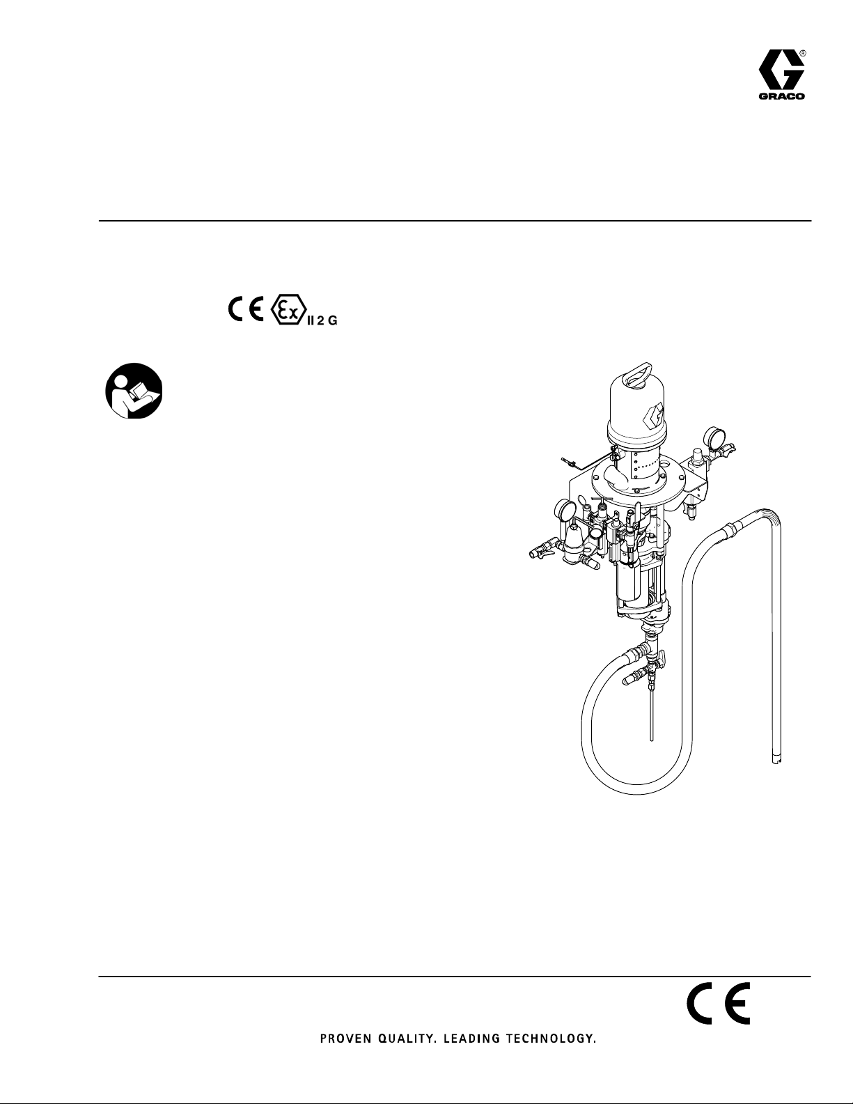
WALL MOUNT, 4–BALL
3:1 Ratio Presidentr
Pump Modules
Used for low pressure, medium volume circulation of
finishing materials. For professional use only.
Pump Modules are certified.
See page 2 for table of contents and list of Models.
Important Safety Instructions
Read all warnings and instructions in this manual and
in 4–Ball Pump manual 3A1450. Save all
instructions.
308768J
EN
232079 Carbon Steel
Pump Module Shown
ti17807a
Page 2
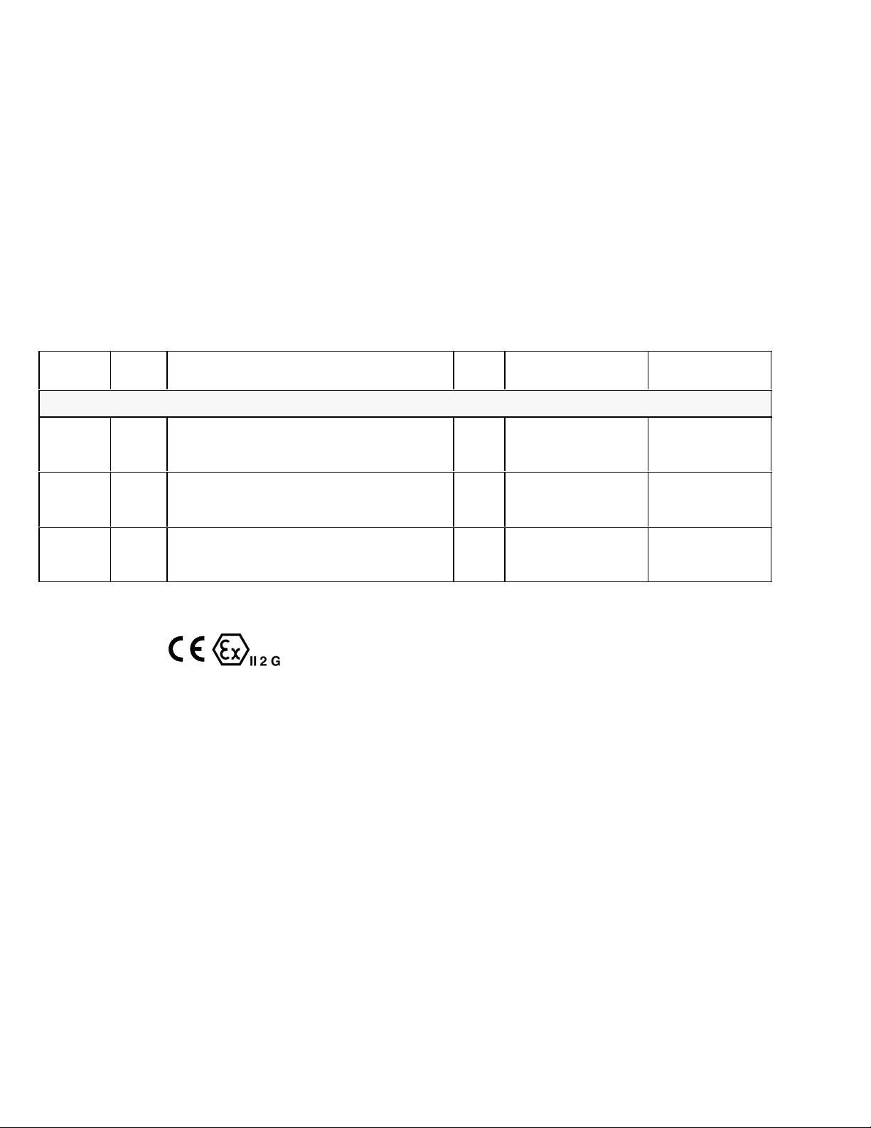
Table of Contents
List of Models 2. . . . . . . . . . . . . . . . . . . . . . . . . . . . . . . . . .
Warnings 3. . . . . . . . . . . . . . . . . . . . . . . . . . . . . . . . . . . . . .
Installation 6. . . . . . . . . . . . . . . . . . . . . . . . . . . . . . . . . . . . .
Operation 11. . . . . . . . . . . . . . . . . . . . . . . . . . . . . . . . . . . .
Maintenance 14. . . . . . . . . . . . . . . . . . . . . . . . . . . . . . . . . .
Parts 16. . . . . . . . . . . . . . . . . . . . . . . . . . . . . . . . . . . . . . . .
Technical Data 20. . . . . . . . . . . . . . . . . . . . . . . . . . . . . . . .
Dimensions 22. . . . . . . . . . . . . . . . . . . . . . . . . . . . . . . . . . .
Mounting Hole Layouts 23. . . . . . . . . . . . . . . . . . . . . . . . .
Graco Warranty 24. . . . . . . . . . . . . . . . . . . . . . . . . . . . . . .
Graco Information 24. . . . . . . . . . . . . . . . . . . . . . . . . . . . .
List of Models
Part No. Series Description Ratio
Pump Modules
*232078 A Stainless steel pump with wall bracket,
air controls, back pressure regulator, and
stainless steel fluid filter
*232079 A Carbon steel pump with wall bracket,
air controls, back pressure regulator, and
Graco Red Alertr carbon steel fluid filter
*232081 A Stainless steel pump with wall bracket,
air controls, back pressure regulator, and
stainless steel fluid filter
3:1 300 psi
3:1 300 psi
3:1 300 psi
Maximum Fluid
Working Pressure
(2.1 MPa, 21 bar)
(2.1 MPa, 21 bar)
(2.1 MPa, 21 bar)
Maximum Air
Input Pressure
100 psi
(0.7 MPa, 7 bar)
100 psi
(0.7 MPa, 7 bar)
100 psi
(0.7 MPa, 7 bar)
*Pump modules are certified.
2 308768
Page 3

Symbols
Warning Symbol
WARNING
This symbol alerts you to the possibility of serious
injury or death if you do not follow the instructions.
WARNING
EQUIPMENT MISUSE HAZARD
Equipment misuse can cause the equipment to rupture or malfunction and result in serious injury.
INSTRUCTIONS
D This equipment is for professional use only.
D Read all instruction manuals, tags, and labels before operating the equipment.
D Use the equipment only for its intended purpose. If you are uncertain about usage, call your Graco
distributor.
Caution Symbol
CAUTION
This symbol alerts you to the possibility of damage to
or destruction of equipment if you do not follow the
instructions.
D Do not alter or modify this equipment. Use only genuine Graco parts and accessories.
D Check equipment daily. Repair or replace worn or damaged parts immediately.
D Do not exceed the maximum working pressure stated on the equipment or in the Technical Data
for your equipment. Do not exceed the maximum working pressure of the lowest rated component
in your system.
D Use fluids and solvents which are compatible with the equipment wetted parts. Refer to the Tech-
nical Data section of all equipment manuals. Read the fluid and solvent manufacturer’s warnings.
D Route hoses away from traffic areas, sharp edges, moving parts, and hot surfaces. Do not expose
Graco hoses to temperatures above 180_F (82_C) or below –40_F (–40_C).
D Wear hearing protection when operating this equipment.
D Do not lift pressurized equipment.
D Comply with all applicable local, state, and national fire, electrical, and safety regulations.
308768 3
Page 4

WARNING
PRESSURIZED EQUIPMENT HAZARD
Spray from the gun, hose leaks, or ruptured components can splash fluid in the eyes or on the skin
and cause serious injury.
D Do not point the gun at anyone or at any part of the body.
D Do not stop or deflect leaks with your hand, body, glove or rag.
D Follow the Pressure Relief Procedure on page 11 whenever you: are instructed to relieve pres-
sure; stop spraying; clean, check, or service the equipment; and install or clean the spray tip.
D Tighten all fluid connections before operating the equipment.
D Check the hoses, tubes, and couplings daily. Replace worn, damaged, or loose parts immediately.
Permanently coupled hoses cannot be repaired; replace the entire hose.
MOVING PARTS HAZARD
Moving parts, such as the air motor piston, elevator, and agitator blades, can pinch or amputate your
fingers.
D Keep clear of all moving parts when starting or operating the pump.
D Keep your hands away from the elevator, pump support, drum cover, and the lip of the drum while
the elevator is operating or is charged with air.
D Always shut off the agitator and disconnect the air line before you remove the agitator from the
drum or check or repair any part of the agitator.
D Before servicing the equipment, follow the Pressure Relief Procedure on page 11 to prevent the
equipment from starting unexpectedly.
4 308768
Page 5
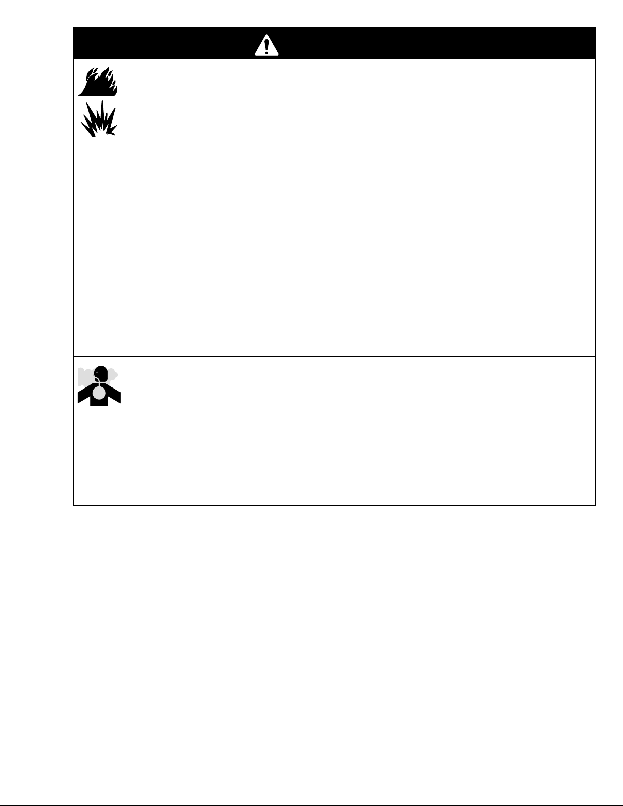
WARNING
FIRE AND EXPLOSION HAZARD
Improper grounding, poor ventilation, open flames or sparks can cause a hazardous condition and
result in a fire or explosion and serious injury.
D Ground the equipment and the object being sprayed. Refer to Grounding on page 10.
D If there is any static sparking or you feel an electric shock while using this equipment, stop spray-
ing immediately. Do not use the equipment until you identify and correct the problem.
D Provide fresh air ventilation to avoid the buildup of flammable fumes from solvents or the fluid
being sprayed.
D Keep the spray area free of debris, including solvent, rags, and gasoline.
D Electrically disconnect all equipment in the spray area.
D Extinguish all open flames or pilot lights in the spray area.
D Do not smoke in the spray area.
D Do not turn on or off any light switch in the spray area while operating or if fumes are present.
D Do not operate a gasoline engine in the spray area.
TOXIC FLUID HAZARD
Hazardous fluid or toxic fumes can cause serious injury or death if splashed in the eyes or on the skin,
inhaled, or swallowed.
D Know the specific hazards of the fluid you are using.
D Store hazardous fluid in an approved container. Dispose of hazardous fluid according to all local,
state, and national guidelines.
D Always wear protective eyewear, gloves, clothing, and respirator as recommended by the fluid and
solvent manufacturer.
308768 5
Page 6

Installation
General Information
NOTE: Reference numbers and letters in parentheses
in the text refer to the callouts in the figures and the
parts drawing.
NOTE: Always use Genuine Graco Parts and Accessories, available from your Graco distributor. If you
supply your own accessories, be sure they are adequately sized and pressure-rated for your system.
Prepare the Operator
All persons who operate the equipment must be
trained in the safe, efficient operation of all system
components as well as the proper handling of all fluids.
All operators must thoroughly read all instruction
manuals, tags, and labels before operating the equipment.
The following manuals are included with this equipment:
D 3A1450, 3:1 President Pump
D 306982, President Air Motor
D 307273, 307282, or 308918, Fluid Filter
D 307068, Fluid Ball Valves
D 308401, Back Pressure Regulator
Prepare the Site
Ensure that the wall is strong enough to support the
weight of the pump and accessories, fluid, hoses, and
stress caused during pump operation.
Ensure that you have an adequate compressed air
supply. Refer to the performance chart on page 21 to
find the air consumption.
Refer to Fig. 2 on page 9. Bring a compressed air
supply line (A) from the air compressor to the pump
location. Be sure all air hoses are properly sized and
pressure-rated for your system. Use only electrically
conductive hoses. The air hose should have a 3/8
npt(m) thread.
Install a bleed-type shutoff valve (B) in the air line to
isolate the air line components for servicing. Install a
moisture trap and drain valve (C) to help remove
moisture and contaminants from the compressed air
supply.
Keep the site clear of any obstacles or debris that
could interfere with the operator’s movement.
Have a grounded, metal pail available for use when
flushing the system.
6 308768
Page 7

Installation
Supplied Components
Refer to Fig. 2 on page 9.
WARNING
A red-handled bleed-type master air valve (11h)
and a fluid drain valve (D) are supplied. These
components help reduce the risk of serious injury,
including splashing of fluid in the eyes or on the
skin, and injury from moving parts if you are adjusting or repairing the pump.
The bleed-type master air valve relieves air trapped
between this valve and the pump after the air is
shut off. Trapped air can cause the pump to cycle
unexpectedly. Locate the valve close to the pump.
The fluid drain valve assists in relieving fluid pressure in the displacement pump, hose, and gun.
Triggering the gun to relieve pressure may not be
sufficient.
D The red-handled bleed-type master air valve
(11h) is required in your system to relieve air
trapped between it and the air motor when the
valve is closed (see the WARNING above). Be sure
the bleed valve is easily accessible from the pump,
and is located downstream from the pump air
filter/regulator (11a).
D The pump air filter/regulator (11a) controls pump
speed and outlet pressure by adjusting the air
pressure to the pump. It includes an air filter with a
40 micron polypropylene element, to remove harmful dirt and moisture from the compressed air
supply. Locate close to the pump, but upstream
from the bleed-type master air valve (11h).
D The air line lubricator (11b) provides automatic
lubrication of the air motor.
D The air relief valve (11j) opens automatically to
prevent overpressurization of the pump.
D Fluid is supplied to the pump through the suction
hose (16) and tube (50). See Fig. 2.
D The fluid filter (5) includes a 60 mesh (250 mi-
cron) stainless steel element to filter particles from
the fluid as it leaves the pump.
D The fluid drain valve (D), is mounted in the bot-
tom of the fluid filter bowl, and is required in your
system to relieve fluid pressure in the hose and gun
(see the WARNING at left).
D The back pressure regulator (12) controls back
pressure to the gun and maintains proper circulation pressure.
Conversion Modules
Supply Module 239857
Part No. 239857 Supply Module is available to convert
a pump module to a circulation package. The supply
module includes an elevator, stainless steel drum
cover, back-geared agitator with suction tube, and
connecting hardware. See manual 308769.
Heater Modules 239850 (120V), 239851 (240V), and
239852 (220/240V)
Three Heater Modules are available to convert a pump
module to a heated system. Each module includes a
heater configured to the desired voltage, and mounting
hardware. See manual 308771.
308768 7
Page 8

Installation
Installing the Pump Module
The pump module consists of the pump mounted on
the pump bracket, the air controls, back pressure
regulator, hoses, and plumbing.
NOTE: Refer to Fig. 2 on page 9, and to the Dimension drawing on page 22 and the Mounting Hole Layout on page 23.
1. Ensure that the wall is strong enough to support
the weight of the pump and accessories, fluid,
hoses, and stress caused during pump operation.
2. Position the bracket mounting plate (37) on the
wall so the edge with the hook is facing up. Mount
the plate so the top edge is 4 to 5 ft (1.2 to 1.5 m)
above the floor. Check that the plate is level. Mark
two holes on the wall, using the plate as a template. Drill two holes and attach the plate with 1/2
in. bolts and washers.
3. Using two people, hang the pump module on the
bracket mounting plate (37). Have one person hold
the module in place while the other checks that the
pump bracket (22) is level. Mark four holes on the
wall, using the pump bracket as a template. Remove the pump module.
4. Drill four holes in the wall.
WARNING
Using the Quick Connectors
To open a quick connector (11c), loosen the captive
screw (S) and open the connector. Slide the desired
component into the connector, close, and tighten the
screw. See Fig. 1.
S
11c
06278
Fig. 1
Connect the Fluid Lines
Connect a 1 to 3 ft (0.3–0.9 m) hose (E) to the ball
valve (15) at the outlet of the fluid filter (5), to isolate
the pump module from the main fluid line. Connect the
other end of the hose to the main fluid line (F).
The pump bracket (22) must be bolted to the wall
with four bolts. Do not simply hang the pump
bracket on the bracket mounting plate (37).
5. Lift the pump module back into position, hang it on
the bracket mounting plate (37), and bolt the pump
bracket (22) to the wall. Use 1/2 in. bolts and
washers to mount the pump module to the wall.
Use bolts that are long enough to keep the pump
bracket (22) from vibrating during operation.
Connect the fluid return line (G) to the ball valve (14) at
the inlet of the back pressure regulator (12). The return
hose (21) connects the back pressure regulator to the
3-way recirculation valve (19).
Connect the Air Line
Connect the main air supply line (A) to the tee (11k) of
the air filter/regulator/lubricator assembly (11).
8 308768
Page 9

Installation
B
A
G
Detail of Air Controls
11a 11b
C
11h
40
F
1
11k
11d
37
22
2
5
11c
11j
11
4
15
12
1
14
24
E
D
21
19
7704c
Pump Module shown installed with a
16
3
239857 Supply Module (not included)
Ensure that there is 9 ft (2.8 m) overhead clearance
1
for the elevator when fully raised.
Mount the pump module so the top of the bracket is
2
4 to 5 ft (1.2 to 1.5 m) above the floor.
The suction hose is 6 ft (1.8 m) long. Do not stretch
3
the hose tight; let it hang as shown, to assist fluid
flow into the pump.
See Detail of Air Controls in upper left corner.
4
Fig. 2
308768 9
Page 10

Installation
Grounding
WARNING
FIRE AND EXPLOSION HAZARD
Before operating the pump, ground the
system as explained below. Also read
the section FIRE AND EXPLOSION
HAZARD on page 5.
1. Pump: use the ground wire and clamp (40, supplied). See Fig. 3. Loosen the grounding lug locknut (W) and washer (X). Insert one end of the
ground wire (40) into the slot in lug (Z) and tighten
the locknut securely. Connect the ground clamp to
a true earth ground.
Z
40
2. Air and fluid hoses: use only electrically conductive
hoses.
3. Air compressor: follow manufacturer’s recommendations.
4. Spray gun: ground through connection to a properly grounded fluid hose and pump.
5. Suction hose: attach the hose (16) ground wire to
the fluid supply container.
6. Fluid supply container: follow your local code.
7. Object being sprayed: follow your local code.
8. Solvent pails used when flushing: follow your local
code. Use only metal pails, which are conductive,
placed on a grounded surface. Do not place the
pail on a nonconductive surface, such as paper or
cardboard, which interrupts the grounding continuity.
Fig. 3
X
W
0720
9. To maintain grounding continuity when flushing or
relieving pressure, hold a metal part of the spray
gun firmly to the side of a grounded metal pail,
then trigger the gun.
10 308768
Page 11

Operation
Pressure Relief Procedure
WARNING
PRESSURIZED EQUIPMENT HAZARD
The system pressure must be manually relieved to
prevent the system from starting or spraying accidentally. To reduce the risk of an injury from accidental spray from the gun, splashing fluid, or
moving parts, follow the Pressure Relief Proce-
dure whenever you:
D are instructed to relieve the pressure,
D stop spraying,
D check or service any of the system equipment,
D or install or clean the spray nozzle.
1. Close the red-handled bleed-type master air valve
(11h, required in your system). See Fig. 4 on page
13.
2. Place the drain hose (42) into a waste container.
Turn the 3-way recirculation valve (19) to the drain
position.
3. Trigger the gun at the last gun station to relieve
fluid pressure. Maintain firm metal-to-metal contact
between the gun and a grounded waste pail.
Repeat for all gun stations.
4. Open the drain valve (D) to relieve fluid pressure
which may be trapped in the pump or hose.
If you suspect that pressure is not fully relieved after
following the steps above, wrap a fitting near the pump
outlet with a rag, and slowly and carefully loosen the
fitting to relieve pressure. Be careful to protect your
eyes from splashing.
Packing Nut
Before starting, fill the packing nut (H) 1/3 full with
Graco Throat Seal Liquid (TSL) or compatible solvent.
See Fig. 4 on page 13.
WARNING
To reduce the risk of serious injury whenever you
are instructed to relieve pressure, always follow the
Pressure Relief Procedure at left.
The packing nut is torqued at the factory and is ready
for operation. If it becomes loose and there is leaking
from the throat packings, relieve pressure, then torque
the nut to 34–40 NSm (25–30 ft-lb). Do this whenever
necessary. Do not overtighten the packing nut.
Flush the Pump Before First Use
The pump is tested with lightweight oil, which is left in
to protect the pump parts. If the fluid you are using
may be contaminated by the oil, flush it out with a
compatible solvent. See Flushing on page 14.
308768 11
Page 12

Operation
Starting and Adjusting the Pump
1. Open all fluid shutoff valves (14, 15). Refer to Fig.
2 on page 9, and to Fig. 4.
2. Open the back pressure regulator (12). Turn the
3-way recirculation valve (19) to the circulation
position.
3. Open the spray gun at the last gun station and
keep it open while starting the pump.
WARNING
COMPONENT RUPTURE HAZARD
To reduce the risk of overpressurizing
your system, which could cause
component rupture and serious injury,
never exceed the specified maximum air input
pressure to the pump (see Technical Data on
page 20).
4. Open the bleed-type master air valves (11h, B).
5. Slowly open the air filter/regulator (11a) until the
pump starts. The air filter/regulator controls the
pump speed and fluid outlet pressure.
6. Adjust the fluid pressure to the lowest setting
necessary to get the desired results. Higher pressures may not improve the spray pattern and will
cause premature component wear. Use the air
filter/regulator (11a) and the back pressure regulator (12) to adjust the pump speed and fluid pressure until the spray is completely atomized. Refer
to the back pressure valve manual (supplied) for
adjustment procedures.
7. To adjust the spray pattern, follow the complete
instructions in your gun manual.
8. When you have achieved the desired spray pattern, release the gun trigger. The pump will continue to cycle as long as air is supplied and the back
pressure regulator (12) is open.
9. One at a time, open any other guns in the system
to purge air from the lines.
NOTE: In a circulating system, the pump will continue
to cycle as long as air is supplied and the back pressure regulator is open. In a direct supply system, the
pump starts when the gun is opened, and stops when
the gun is closed.
CAUTION
Do not allow the pump to run dry. It will quickly
accelerate to a high speed, causing damage. If your
pump is running too fast, stop it immediately and
check the fluid supply. If the container is empty and
air has been pumped into the lines, refill the container and prime the pump and the lines, or flush and
leave it filled with a compatible solvent. Eliminate all
air from the fluid system.
Shutdown
WARNING
To reduce the risk of serious injury whenever you
are instructed to relieve pressure, always follow the
Pressure Relief Procedure on page 11.
Relieve the pressure.
For overnight shutdown, stop the pump at the bottom
of its stroke to prevent fluid from drying on the exposed displacement rod and damaging the throat
packings. Relieve the pressure.
Always flush the pump before the fluid dries on the
displacement rod. See Flushing on page 14.
NOTE: When changing fluid containers with the hose
and gun already primed, open the drain valve (D) to
help prime the pump and vent air before it enters the
hose. Close the drain valve when all air is eliminated.
12 308768
Page 13

Torque packing nut (H) to 34–40 NSm (25–30 ft-lb).
1
Packing nut is partially hidden.
Operation
14
11a
12
11h
H
19
15
5
D
1
Fig. 4
42
21
ti17807a
308768 13
Page 14

Maintenance
Preventive Maintenance Schedule
The operating conditions of your particular system
determine how often maintenance is required. Establish a preventive maintenance schedule by recording
when and what kind of maintenance is needed, and
then determine a regular schedule for checking your
system.
Flushing
WARNING
FIRE AND EXPLOSION HAZARD
Before flushing, read the section FIRE
AND EXPLOSION HAZARD on page
5. Be sure the entire system and flushing pails are properly grounded. Refer to
Grounding on page 10.
Flush the pump:
D Before the first use
D When changing colors or fluids
3. Remove the filter element from the fluid filter (5).
Reinstall the filter bowl.
4. Open the back pressure regulator (12). Set the
3-way recirculation valve (19) to the circulation
position.
5. Place the suction tube (50) in a container of solvent.
6. Hold a metal part of the gun firmly to the side of a
grounded metal pail.
7. Start the pump. Always use the lowest possible
fluid pressure when flushing.
8. Trigger the gun. Flush the system until clear
solvent flows from the gun.
9. Release the gun trigger and lock the trigger safety.
The pump will continue to cycle as long as air is
supplied and the back pressure regulator (12) is
open.
10. Direct the drain hose (42) into a waste container.
Set the 3-way recirculation valve (19) to the drain
position. Continue flushing until clear fluid comes
from the hose.
D Before fluid can dry or settle out in a dormant pump
(check the pot life of catalyzed fluids)
D Before storing the pump.
Flush with a fluid that is compatible with the fluid you
are pumping and with the wetted parts in your system.
Check with your fluid manufacturer or supplier for
recommended flushing fluids and flushing frequency.
CAUTION
If you have a carbon steel pump, never leave water
or water-base fluid in the pump overnight. If you are
pumping water-base fluid, flush with water first, then
with a rust inhibitor such as mineral spirits. Relieve
the pressure, but leave the rust inhibitor in the pump
to protect the parts from corrosion.
WARNING
To reduce the risk of serious injury whenever you
are instructed to relieve pressure, always follow the
Pressure Relief Procedure on page 11.
11. Relieve the pressure.
12. Clean the air cap, spray tip, and fluid filter element
separately, then reinstall them.
Air Filter Service
Repair Kits are available. Refer to page 15.
Every day, drain contaminants from the bowl before
reaching the baffle level by opening the drain (P) at the
bottom of the bowl (N).
WARNING
To reduce the risk of serious injury whenever you
are instructed to relieve pressure, always follow the
Pressure Relief Procedure on page 11.
Clean the air filter regularly to maximize filtering efficiency and to avoid excessive pressure drop. Fully
relieve pressure to remove the bowl (N).
Clean the filter element (211) and bowl using household soap and water or denatured alcohol. Use compressed air to blow out the filter body. Blow the filter
element out from the inside.
1. Relieve the pressure.
2. Remove the air cap and spray tip from the gun.
See the gun manual.
14 308768
Clean the sight glass (209) thoroughly. Do not leave
solvent residue in the sight glass as it may attack or
weaken the glass. If the sight glass appears damaged,
replace it immediately.
Page 15

Maintenance
Repair Kit 239383 (includes items 201 to
Model 113765
Air Filter/Regulator Shown
1
1
Lubricate with no. 2
1
lithium-base grease.
201*
207). For Part No. 113765 Air
Filter/Regulator.
Kit parts are marked with an asterisk (201*). Individual
parts are not available separately.
Ref.
No. Part No. Description Qty.
201* N/A DIAPHRAGM 1
202* N/A VALVE ASSEMBLY 1
203* N/A O-RING, valve 1
204* N/A SPRING, valve 1
205* N/A O-RING, center post 1
206* N/A O-RING, bowl assembly 1
207* N/A GASKET, drain 1
Sight Glass Kit 239385 (includes items
206 to 210). For Part No. 113765 Air
Filter/Regulator.
Kit parts are marked with a symbol (208{). Individual
parts are not available separately.
202*
203*
204*
205*
211}
206*{
Ref.
No. Part No. Description Qty.
1
1
1
206{ N/A O-RING, bowl assembly 1
208{ N/A SCREW 2
209{ N/A LENS, sight glass 1
210{ N/A SEAL, lens 1
Filter Element Kit 239384 (includes item
211). For Part No. 113765 Air
Filter/Regulator.
Kit parts are marked with a symbol (211}). Individual
parts are not available separately.
Ref.
No. Part No. Description Qty.
211} N/A ELEMENT, 40 micron; polypropylene 1
1
210{
N
209{
208{
P
207*
1
05998
308768 15
Page 16

Parts
6
7
Part No. 232078, Series B, stainless steel pump module
Part No. 232079, Series B, carbon steel pump module (shown)
Part No. 232081, Series B, stainless steel pump module
40
10
A
50
14
12
21 (Ref)
323
56
2
11f
38
11k
A
11e
11d
11n
11j
11c
4
29
11a
C
11b
11d
11c
39
32
33
10 (Ref)
11g
11h
31
9
1
16
20
31
24
11k
11m
48
22
37
32
33
18
5
45
4
4
15
B
C
21 41
16 308768
16
27
B
6
7
8
18
19
26
42
Fluid Filter Detail for
Model 232081
5
18
48
47
46
45
15
Fluid Filter Detail for
Model 232078
5
15
7685d
Page 17

Parts
Part No. 232078, Series B, stainless steel pump module
Part No. 232079, Series B, carbon steel pump module (shown)
Part No. 232081, Series B, stainless steel pump module
NOTE: Part numbers vary by module. To find the part number used in your module, read down the chart to find the
desired ref. no., then read left to right to find the part number for your module.
Ref.
No. Description
1 PUMP, President; 3:1 ratio; sst; see manual 3A1450 24J075 24J075 1
PUMP, President; 3:1 ratio; cst; see manual 3A1450 24J074 1
2 BUSHING; sst; 1” npt(m) x 1/2 npt(f) 513299 513299 513299 1
3 ELBOW, 90_; sst; 1/2 npt(fbe) 500947 500947 500947 1
4 NIPPLE, reducing; sst; 1/2 npt x 3/8 npt 111874 1
NIPPLE, reducing; sst; 3/4 npt x 1/2 npt 192593 192593 1
5 FLUID FILTER, includes drain valve and gauge; sst;
see manual 307273
FLUID FILTER; sst; see manual 307282 213058 1
FLUID FILTER; sst; see manual 308918 244053 1
6 BUSHING; sst; 1–1/2” npt(m) x 3/4 npt(f) 114188 114188 114188 1
7 NIPPLE; sst; 3/4 npt 510073 510073 510073 1
8 TEE; sst; 3/4 npt(f) run x 3/4 npt(f) branch 113833 113833 113833 1
9 ELBOW, tube fitting, 90_; 1/2 npt(m) x 1/2 in. (13 mm) OD tube 114110 114110 114110 1
10 HOSE; polyurethane; 0.328 in. (8 mm) ID; 13 in. (330 mm) long Purchase
11 AIR FILTER/REGULATOR/LUBRICATOR; see page 15;
includes items 11a to 11m
11a . AIR FILTER/REGULATOR 113765 113765 113765 1
11b . LUBRICATOR 114005 114005 114005 1
11c . CONNECTOR, quick 113763 113763 113763 3
11d . ADAPTER, pipe; 3/8 npt(f) 113767 113767 113767 2
11e . ELBOW, 45_; 1/8 npt (m x f) 113630 113630 113760 1
11f . GAUGE, air 113911 113911 113911 1
11g . ADAPTER, tube fitting; 1/2 npt(m) x 1/2 in. (13 mm) OD tube 114129 114129 114129 1
11h . VALVE, ball, bleed-type; 3/8 npt (m x f) 113333 113333 113333 1
11j . VALVE, relief; 110 psi (7.6 bar, 0.76 MPa) 113498 113498 113498 1
11k . TEE; 3/8 npt(f) run x 3/8 npt(m) branch 113777 113777 113777 2
11m . PLUG; 3/8 npt 101754 101754 101754 1
11n . ADAPTER; 3/8 npt(m) x 1/4 npt(f) 159841 159841 159841 1
12 REGULATOR, back pressure; see manual 308401 236770 236770 236770 1
14 VALVE, ball; sst; 3/8 npt(fbe); see manual 307068 237532 237532 237532 1
15 VALVE, ball; sst; 1/4 npt(m) x 3/8 npsm(m); see manual 307068 237529 1
VALVE, ball; sst; 3/8 npt(m) x 3/8 npsm(m); see manual 307068 237533 237533 1
232078
SST Module
239853 1
locally
239849 239849 239849 1
Module
232079
CST Module
Purchase
locally
232081
SST Module
Purchase
locally
Qty
1
NOTE: The Parts List is continued on page 18.
308768 17
Page 18

Parts
Part No. 232078, Series B, stainless steel pump module
Part No. 232079, Series B, carbon steel pump module
Part No. 232081, Series B, stainless steel pump module
NOTE: Part numbers vary by module. To find the part number used in your module, read down the chart to find the
desired ref. no., then read left to right to find the part number for your module.
Ref.
No. Description
16 HOSE, suction, with ground wire; nylon;
3/4 npt(mbe) sst couplings; 1/2 in. (13 mm) ID; 6 ft (1.8 m) long
18 BUSHING; sst; 3/4 npt(m) x 3/8 npt(f) 500352 1
BUSHING; sst; 3/4 npt(m) x 3/8 npt(f) 500352 500352 2
19 VALVE, recirculation, 3-way; sst; 3/8 npt(m) 114189 114189 114189 1
20 SWIVEL, 90_; sst; 3/8 npt(m) x 3/8 npsm(f) 207123 207123 207123 1
21 HOSE, fluid return; nylon; 3/8 npt(mbe) sst couplings;
1/4” (6 mm) ID; 6 ft (1.8 m) long
22 BRACKET, pump 192584 192584 192584 1
23 UNION, swivel; 1/2 npt(m) x 1/2 npsm(f); sst 114190 114190 114190 1
24 BRACKET, back pressure regulator 192586 192586 192586 1
26 COUPLING, hose, with spring guard; sst; 3/8 npsm(f) 111914 111914 111914 1
27 SWIVEL; 3/4 npt (m x f); sst 112268 112268 112268 1
29 SCREW, cap, socket hd; 1/4–20; 1/2 in. (13 mm) long 101550 101550 101550 2
31 SCREW, cap, hex head; 3/8–16 x 1 in. (25 mm) long 102471 102471 102471 5
32 LOCKWASHER, spring; 3/8 103975 103975 103975 5
33 NUT, hex; 3/8–16 112913 112913 112913 5
37 PLATE, mounting, bracket 192589 192589 192589 1
38 SCREW, machine, socket, flat head; M5 x 0.8; 16 mm long 113768 113768 113768 6
39 NUT, hex, with nylon insert; M5 x 0.8 105332 105332 105332 6
40 GROUND WIRE AND CLAMP 237569 237569 237569 1
41 SWIVEL, straight; 3/8 npt(f) x 3/8 npsm(f) 207152 207152 207152 1
42 TUBE, drain; nylon; 1/4 in. (6 mm) ID; 8 in. (203 mm) long Purchase
45 TEE; sst; 3/8 npt(f) x 3/8 npt(m) run; 3/8 npt(f) branch 108673 108673 1
46 BUSHING; sst; 3/8 npt(m) x 1/4 npt(f) 168160 168160 1
47 GAUGE, fluid pressure; sst; 0–300 psi (0–21 bar, 0–2.1 MPa) 187876 187876 1
48 VALVE, ball; sst; 1/4 npt(m) x 3/8 npsm(m); see manual 307068 237529 237529 1
49 THROAT SEAL LIQUID; 1 pint (0.5 liter); not shown 206994 206994 206994 1
50 TUBE, suction, 90_; sst; 3/4 npt(f) x 3/4 npsm(m) 188867 188867 188867 1
56 NIPPLE; sst; 1/2 npt 114373 114373 114373 1
232078
SST Module
221171 221171 221171 1
114198 114198 114198 1
locally
Module
232079
CST Module
Purchase
locally
232081
SST Module
Purchase
locally
Qty
1
18 308768
Page 19

Notes
308768 19
Page 20

Technical Data
Part No. 232078, Series B, stainless steel pump module
Part No. 232079, Series B, carbon steel pump module
Part No. 232081, Series B, stainless steel pump module
Category Data
Maximum fluid working pressure 300 psi (2.1 MPa, 21 bar)
Maximum air input pressure 100 psi (0.7 MPa, 7 bar)
Ratio 3:1
Maximum operating temperature Models 232078 and 232079: 180_F (82_C)
Model 232081: 150_F (66_C)
Weight Stainless steel models: 114 lb (52.7 kg)
Carbon steel models: 112 lb (51.8 kg)
Wetted parts Pump: See pump manual 308793.
Fluid Filter: See filter manual 307273, 307282, or 308918.
Back Pressure Regulator: See back pressure regulator manual 308401.
Fluid Hoses: Nylon
Sound Pressure Levels (dBa)
(measured at 1 meter from unit)
Input Air Pressures at 15 cycles per minute
Air Motor 40 psi (0.28 MPa, 2.8 bar) 70 psi (0.48 MPa, 4.8 bar) 100 psi (0.7 MPa, 7 bar)
President 73.6 dB(A) 78.3 dB(A) 80.9 dB(A)
Sound Power Levels (dBa)
(tested in accordance with ISO 9614–2)
Input Air Pressures at 15 cycles per minute
Air Motor 40 psi (0.28 MPa, 2.8 bar) 70 psi (0.48 MPa, 4.8 bar) 100 psi (0.7 MPa, 7 bar)
President 87.4 dB(A) 92.1 dB(A) 94.6 dB(A)
20 308768
Page 21

MPa, BAR
2.8, 28
2.45, 24.5
PSI
400
350
Technical Data
Fluid Outlet Pressure Chart
CPM
12 25 37 49 61 73
86
A 0.7 MPa, 7 bar (100 psi) air pressure
B 0.49 MPa, 4.9 bar (70 psi) air pressure
C 0.28 MPa, 2.8 bar (40 psi) air pressure
0.7, 7
1.96
1.68
1.40
1.12
0.84
0.56
0.28
300
250
200
150
100
50
0
02468101214
GPM
l/min
PUMP DELIVERY (Test Fluid: No. 10 Motor Oil)
CFMm3/min
70
60
50
40
30
20
10
2.1, 21
1.7, 17
1.4, 14
1.05, 10.5
PUMP OUTLET PRESSURE
0.35, 3.5
AIR CONSUMPTION
A
B
C
8 1523 3038 4654
Air Consumption Chart
CPM
12 25 37 49 61 73
A
B
C
86
To find Outlet Pressure (MPa/bar/psi) at a specific
delivery (liter/min or gpm) and operating air pressure
(MPa/bar/psi):
1. Locate desired delivery along bottom of chart.
2. Read vertical line up to intersection with
selected fluid outlet pressure curve (black
curves). Curve slopes from left to right.
Follow left to scale and read outlet pressure.
A 0.7 MPa, 7 bar (100 psi) air pressure
B 0.49 MPa, 4.9 bar (70 psi) air pressure
C 0.28 MPa, 2.8 bar (40 psi) air pressure
To find Pump Air Consumption (m3/min or
CFM/min) at a specific delivery (liter/min or gpm)
and operating air pressure (MPa/bar/psi):
1. Locate desired delivery along bottom of chart.
2. Read vertical line up to intersection with
selected air consumption curve (dashes).
Curve slopes from right to left. Follow left to
scale and read air consumption.
0
02468101214
GPM
l/min
PUMP DELIVERY (Test Fluid: No. 10 Motor Oil)
8 1523 3038 4654
308768 21
Page 22

Mount the pump module so the top of the bracket is
2
4 to 5 ft (1.2 to 1.5 m) above the floor.
The suction hose is 6 ft (1.8 m) long. Do not stretch
3
the hose tight; let it hang as shown, to assist fluid
flow into the pump.
Dimensions
50.1 in.
(1273 mm)
33.2 in.
(843 mm)
2
3
ti17807aFloor
22 308768
Page 23

Mounting Hole Layout
1
Check that the bracket is level before bolting it to the wall.
2
Mount the bracket so the top edge is 4 to 5 ft (1.2 to 1.5 m) above the floor.
2
4.0 in.
(101.6 mm)
1
1.0 in. (25.4 mm)
5.0 in.
(127 mm)
10.0 in.
(254 mm)
7687A
308768 23
Page 24

Graco Standard Warranty
Graco warrants all equipment manufactured by Graco and bearing its name to be free from defects in material and workmanship on the
date of sale to the original purchaser for use. With the exception of any special, extended, or limited warranty published by Graco,
Graco will, for a period of twelve months from the date of sale, repair or replace any part of the equipment determined by Graco to be
defective. This warranty applies only when the equipment is installed, operated and maintained in accordance with Graco’s written
recommendations.
This warranty does not cover, and Graco shall not be liable for general wear and tear, or any malfunction, damage or wear caused by
faulty installation, misapplication, abrasion, corrosion, inadequate or improper maintenance, negligence, accident, tampering, or substitution of non–Graco component parts. Nor shall Graco be liable for malfunction, damage or wear caused by the incompatibility of
Graco equipment with structures, accessories, equipment or materials not supplied by Graco, or the improper design, manufacture,
installation, operation or maintenance of structures, accessories, equipment or materials not supplied by Graco.
This warranty is conditioned upon the prepaid return of the equipment claimed to be defective to an authorized Graco distributor for
verification of the claimed defect. If the claimed defect is verified, Graco will repair or replace free of charge any defective parts. The
equipment will be returned to the original purchaser transportation prepaid. If inspection of the equipment does not disclose any defect
in material or workmanship, repairs will be made at a reasonable charge, which charges may include the costs of parts, labor, and
transportation.
THIS WARRANTY IS EXCLUSIVE, AND IS IN LIEU OF ANY OTHER WARRANTIES, EXPRESS OR IMPLIED, INCLUDING BUT
NOT LIMITED TO WARRANTY OF MERCHANTABILITY OR WARRANTY OF FITNESS FOR A PARTICULAR PURPOSE.
Graco’s sole obligation and buyer’s sole remedy for any breach of warranty shall be as set forth above. The buyer agrees that no other
remedy (including, but not limited to, incidental or consequential damages for lost profits, lost sales, injury to person or property, or any
other incidental or consequential loss) shall be available. Any action for breach of warranty must be brought within two (2) years of the
date of sale.
Graco makes no warranty, and disclaims all implied warranties of merchantability and fitness for a particular purpose in connection
with accessories, equipment, materials or components sold but not manufactured by Graco. These items sold, but not manufactured
by Graco (such as electric motors, switches, hose, etc.), are subject to the warranty, if any, of their manufacturer. Graco will provide
purchaser with reasonable assistance in making any claim for breach of these warranties.
In no event will Graco be liable for indirect, incidental, special or consequential damages resulting from Graco supplying equipment
hereunder, or the furnishing, performance, or use of any products or other goods sold hereto, whether due to a breach of contract,
breach of warranty, the negligence of Graco, or otherwise.
FOR GRACO CANADA CUSTOMERS
The parties acknowledge that they have required that the present document, as well as all documents, notices and legal proceedings
entered into, given or instituted pursuant hereto or relating directly or indirectly hereto, be drawn up in English. Les parties reconnaissent avoir convenu que la rédaction du présente document sera en Anglais, ainsi que tous documents, avis et procédures judiciaires
exécutés, donnés ou intentés à la suite de ou en rapport, directement ou indirectement, avec les procedures concernées.
Graco Information
For the latest information about Graco products, visit www.graco.com.
TO PLACE AN ORDER, contact your Graco distributor or call to identify the distributor closest to you:
Phone: 612–623–6921 or Toll Free: 1–800–328–0211 Fax: 612–378–3505
All written and visual data contained in this document reflects the latest product information available at the time of publication.
Graco reserves the right to make changes at any time without notice.
24 308768
Original instructions. This manual contains English. MM 308768
Graco Headquarters: Minneapolis
International Offices: Belgium, China, Japan, Korea
GRACO INC. P.O. BOX 1441 MINNEAPOLIS, MN 55440–1441
Copyright 1997, Graco Inc. is registered to ISO 9001
www.graco.com
Revised 08/2011
 Loading...