

Page 1
Instructions - Parts List
9038B
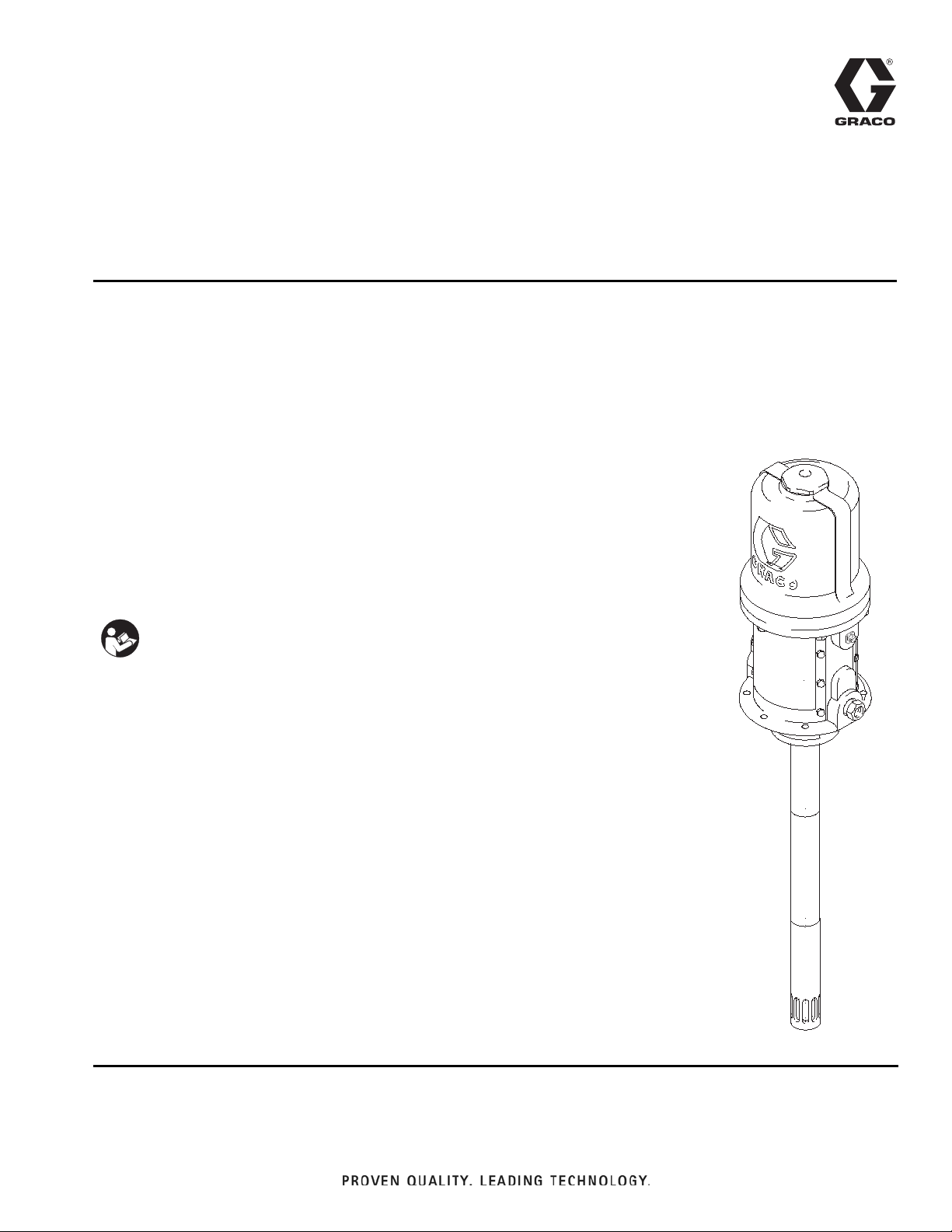
50:1 Mini Fire-Ball
225 Grease Pump
309966H
For pumping non-corrosive and non-abrasive greases and lubricants only. For
professional use only.
Not for use in explosive atmospheres.
Model No. 246909, Series C, Pail Length
Model No. 246780, Series C, 120-lb Drum Length
Model No. 246781, Series C, 400-lb Drum Length
Model No. 253361, Series C, Pail Length Without Handle
8400 psi (58 MPa, 580 bar) Maximum Working Pressure
140 psi (1.0 MPa, 10 bar) Maximum Air Working Pressure
Important Safety Instructions
Read all warnings and instructions in this manual.
Save these instructions.
EN
Table of Contents
Warnings . . . . . . . . . . . . . . . . . . . . . . . . . . . . . . . . . 2
Installation . . . . . . . . . . . . . . . . . . . . . . . . . . . . . . . . 4
Operation . . . . . . . . . . . . . . . . . . . . . . . . . . . . . . . . . 6
Troubleshooting . . . . . . . . . . . . . . . . . . . . . . . . . . . 7
Displacement Pump Service . . . . . . . . . . . . . . . . . . 8
Air Motor and Throat Service . . . . . . . . . . . . . . . . 11
Parts . . . . . . . . . . . . . . . . . . . . . . . . . . . . . . . . . . . . 14
Dimensional Drawings . . . . . . . . . . . . . . . . . . . . . 16
Mounting Hole Layout . . . . . . . . . . . . . . . . . . . . . . 16
Technical Data . . . . . . . . . . . . . . . . . . . . . . . . . . . . 17
Graco Standard Warranty . . . . . . . . . . . . . . . . . . . 18
Graco Information . . . . . . . . . . . . . . . . . . . . . . . . . 18
Model No. 246780 shown
Page 2
Warnings
Warnings
The following general warnings are for the setup, use, grounding, maintenance, and repair of this equipment. Additional, more specific warnings may be found throughout the body of this manual where applicable. Symbols appear-
ing in the body of the manual refer to these general warnings. When these symbols appear throughout the manual,
refer back to these pages for a description of the specific hazard.
WARNING
EQUIPMENT MISUSE HAZARD
Misuse can cause death or serious injury.
• Do not operate the unit when fatigued or under the influence of drugs or alcohol.
• Do not exceed the maximum working pressure or temperature rating of the lowest rated system
component. See Technical Data in all equipment manuals.
• Use fluids and solvents that are compatible with equipment wetted parts. See Technical Data in all
equipment manuals. Read fluid and solvent manufacturer’s warnings. For complete information
about your material, request MSDS forms from distributor or retailer.
• Check equipment daily. Repair or replace worn or damaged parts immediately with genuine Graco
replacement parts only.
• Do not alter or modify equipment.
• Use equipment only for its intended purpose. Call your Graco distributor for information.
• Route hoses and cables away from traffic areas, sharp edges, moving parts, and hot surfaces.
• Do not kink or over bend hoses or use hoses to pull equipment.
• Keep children and animals away from work area.
• Comply with all applicable safety regulations.
SKIN INJECTION HAZARD
High-pressure fluid from dispense valve, hose leaks, or ruptured components will pierce skin. This may
look like just a cut, but it is a serious injury that can result in amputation. Get immediate surgical
treatment.
• Do not point dispense valve at anyone or at any part of the body.
• Do not put your hand over the end of the dispense nozzle.
• Do not stop or deflect leaks with your hand, body, glove, or rag.
• Follow Pressure Relief Procedure in this manual, when you stop dispensing and before cleaning,
checking, or servicing equipment.
MOVING PARTS HAZARD
Moving parts can pinch or amputate fingers and other body parts.
• Keep clear of moving parts.
• Do not operate equipment with protective guards or covers removed.
• Pressurized equipment can start without warning. Before checking, moving, or servicing equipment,
follow the Pressure Relief Procedure in this manual. Disconnect power or air supply.
2 309966H
Page 3
Warnings
WARNING
FIRE AND EXPLOSION HAZARD
When flammable fluids are present in the work area, such as gasoline and windshield wiper fluid, be
aware that flammable fumes can ignite or explode. To help prevent fire and explosion:
• Use equipment only in well ventilated area.
• Eliminate all ignition sources, such as cigarettes and portable electric lamps.
• Keep work area free of debris, including rags and spilled or open containers of solvent and gasoline.
• Do not plug or unplug power cords or turn lights on or off when flammable fumes are present.
• Ground all equipment in the work area.
• Use only grounded hoses.
• If there is static sparking or you feel a shock, stop operation immediately. Do not use equipment
until you identify and correct the problem.
• Keep a working fire extinguisher in the work area.
TOXIC FLUID OR FUMES HAZARD
Toxic fluids or fumes can cause serious injury or death if splashed in the eyes or on skin, inhaled, or
swallowed.
• Read MSDS’s to know the specific hazards of the fluids you are using.
• Store hazardous fluid in approved containers, and dispose of it according to applicable guidelines.
PERSONAL PROTECTIVE EQUIPMENT
You must wear appropriate protective equipment when operating, servicing, or when in the operating
area of the equipment to help protect you from serious injury, including eye injury, inhalation of toxic
fumes, burns, and hearing loss. This equipment includes but is not limited to:
• Protective eyewear
• Clothing and respirator as recommended by the fluid and solvent manufacturer
• Gloves
• Hearing protection
309966H 3
Page 4
Installation
TI1052
Z
Y
Installation
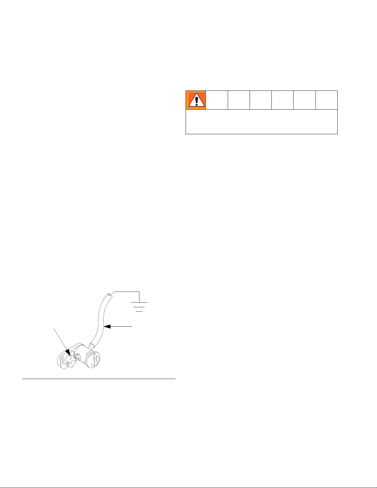
Grounding
Proper grounding is an essential part of maintaining a
safe system.
To reduce the risk of static sparking, ground the pump.
Check your local electrical code for detailed grounding
instructions for your area and type of equipment.
Ground the following equipment:
• Pump: Use a ground wire and clamp as shown in
F
IG. 1.
• Fluid hoses: Use only electrically conductive hoses.
• Air compressor: Follow the manufacturer’s recommendations.
• Fluid supply container: Follow the local code.
• To maintain grounding continuity when flushing or
relieving pressure, always hold a metal part of the
valve firmly to the side of a grounded metal pail,
then trigger the valve.
To ground the pump, remove the ground screw (Z)
and insert through the eye of the ring terminal at end of
the ground wire (Y). Fasten the ground screw back onto
the pump and tighten securely. Connect the other end of
the ground wire to a true earth ground. See F
order a ground wire and clamp, order Part No. 222011.
IG. 1. To
Mounting
Mount the pump securely so that it cannot move
around during operation. Failure to do so could result in
personal injury or equipment damage.
1. Plan the mounting layout for easy operator access
to the pump air controls, sufficient room to change
drums and a secure mounting platform.
2. If using a follow plate (H), remove the drum cover.
Scoop the material to the center of the drum to
make the surface convex. Place the plate on the
material. Guide the pump foot valve through the
plate.
3. Mount the pump to the drum cover or other suitable
mounting device.
4. Install a pump elevator for easier changing of
drums,
F
IG. 1
4 309966H
Page 5
Installation
04191C
A
B
C
D
E
F
G
H
J
K
J
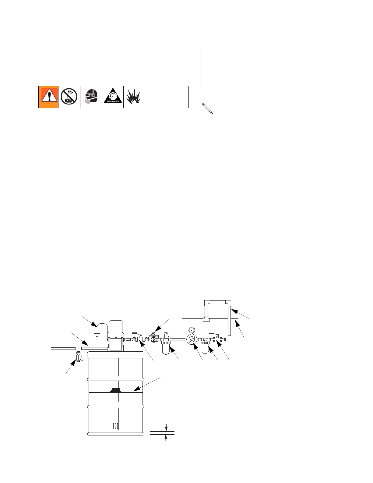
Recommended air line
configuration to reduce
moisture in pump
KEY
A Fluid dispense line
B Pump ground wire (required)
C Air regulator with gauge
D Main air supply line
E Air line filter
F Air line lubricator
G Pump runaway valve
H Follower plate
J Bleed-type master air valves
(required)
K Fluid drain valve
1/2 in.
Air and Fluid Line and Accessories
See FIG. 2.
Three accessories are required in your system: an air
shut-off valve/air bleed device, fluid drain valve, and
ground wire. These accessories help reduce the risk of
serious bodily injury, including skin injection, splashing
in the eyes or on the skin, injury from moving parts if you
are adjusting or repairing the pump, and explosion from
static sparking.
• The air bleed device relieves air trapped between it
and the air motor after the air supply is shut off.
Trapped air can cause the air motor to cycle unexpectedly, causing serious injury if you are adjusting
or repairing the pump. Use a bleed-type master air
valve (J), installed near the pump air inlet within
easy reach from the pump.
• The fluid drain valve (K) assists in relieving fluid
pressure in the displacement pump, hoses, and dispensing valve. Triggering the valve to relieve pressure may not be sufficient.
• The ground wire (B) reduces the risk of static sparking.
CAUTION
Do not hang the air accessories directly on the air
inlet. The fittings are not strong enough to support the
accessories and may cause one or more to break.
Provide a bracket on which to mount the accessories.
Install the air line accessories in the order shown in
F
IG. 2.
1. Install a pump runaway valve (G) to shut off the air
to the pump if the pump accelerates beyond the
pre-adjusted setting. A pump that runs too fast can
be seriously damaged.
2. Install an air line lubricator (F) for automatic air
motor lubrication.
3. Install a bleed-type master air valve (J) to relieve air
trapped between the valve and the motor. Order
Part No. 107142.
4. Install an air regulator (C) to control pump speed
and pressure.
5. Install an air line filter (E) to remove harmful dirt and
contaminants from your compressed air supply.
6. Install a second bleed-type master air valve (J)
upstream from all other accessories, to isolate the
accessories for servicing.
Typical Installation for Stationary Mountings
FIG. 2
309966H 5
Page 6
Operation
Operation
Pressure Relief Procedure
The equipment stays pressurized until pressure is manually relieved. To reduce the risk of serious injury from
pressurized fluid, fluid from the valve, or splashing fluid,
follow this procedure whenever you:
• are instructed to relieve pressure
• stop dispensing
• check, clean, or service any system equipment
• install or clean dispensing devices.
1. Close the pump air regulator and the bleed–type
master air valve (required in your system).
2. Hold a metal part of the dispensing valve firmly to a
grounded metal waste container and trigger the
valve to relieve the fluid pressure.
The pump has a rated ratio of 50:1. However, it is
capable of reaching stall pressures equal to 60
times the air input pressure. Calculate the fluid output pressure using the air regulator reading. Multiply the air pressure shown on the regulator gauge
by 60. For example:
140 psi air x 60 = 8400 psi fluid output)
(0.97 MPa air = 58.2 MPa fluid output
99.7 bar air x 60 = 582 bar fluid output
Regulate air to the pump so that no air line or fluid
line component or accessory is overpressurized.
6. Never allow the pump to run dry of the material
being pumped.
Startup
1. If there are multiple pumps on the air line, close the
air regulators and bleed–type master air valves to all
but one pump. If there is only one pump, close its air
regulator and bleed–type master air valve.
2. Open the master air valve from the compressor.
3. Open the dispensing valve into a grounded metal
waste container, making firm metal–to–metal contact between the container and valve. Open the
bleed–type master air valve and open the pump air
regulator slowly, just until the pump is running.
When the pump is primed and all air has been
pushed out of the lines, close the dispense valve.
4. If you have more than one pump, repeat this procedure for each pump.
When the pump is primed, and with sufficient air
supplied, the pump starts when the dispensing
valve is opened and shuts off when it is closed.
CAUTION
A dry pump will quickly accelerate to a high speed,
possibly damaging itself. If your pump accelerates
quickly, or is running too fast, stop it immediately and
check the material supply. If the supply container is
empty and air has been pumped into the lines, prime
the pump and lines with material, or flush it and leave
it filled with a compatible solvent. Be sure to eliminate
all air from the material lines.
A pump runaway valve can be installed on the air
line to automatically shut off the pump if it starts to
run too fast.
7. Read and follow the instructions supplied with each
component in your system.
8. To shut off the system, always follow the Pressure
Relief Procedure.
5. Set the air pressure to each pump at the lowest
pressure needed to get the desired results.
6 309966H
Page 7

Troubleshooting
Relieve pressure before you check or service any
system equipment.
Problem Cause Solution
Pump fails to operate Inadequate air supply pressure or
restricted air lines
Closed or clogged pump valves Open and/or clean.
Clogged fluid line, hose, valve, or
other accessory
Damaged air motor Assess damage, and service air
Exhausted fluid supply Refill and reprime or flush.
Continuous air exhaust Worn or damaged air motor
gasket or seal
Erratic pump operation Exhausted fluid supply Refill and reprime or flush.
Worn pump seals Replace.
Damaged shovel tube Replace.
Damaged check seat Replace pump piston or shovel rod
Errataic or accelerated pump speed Exhausted fluid supply Refill and reprime of flush.
Fluid too heavy for pump priming Use inductor or follow plate.
Held open or worn piston valve or
seal
Held open or worn intake valve or
seal.
Pump operates, but output low on up
stroke
Pump operates, but output low on
down stroke
Pump operates, but output low on
both strokes
Grease leaking from muffler plates Worn throat seal Replace.
Worn piston seal Replace.
Damaged upper check seat Replace pump piston.
Worn fluid intake seal Replace.
Damaged lower check seat Replace shovel rod.
Inadequate air supply pressure or
restricted air lines
Closed or clogged pump valves Open and/or clean.
Exhausted fluid supply Refill fluid supply, and reprime pump.
Clogged fluid line, hose, valve, or
other accessory
Worn seals Replace.
Increase air supply and/or clear
restriction.
Relieve pressure.
Clear obstruction.
motor.
Assess wear or damage, and service
air motor.
(or other damaged part).
Clear valve; replace seal.
Clear valve; replace seal.
Increase air supply and/or clear
restriction.
Relieve pressure.
Clear obstruction.
Troubleshooting
309966H 7
Page 8

Displacement Pump Service
Correct Alignment
Permits end play
Fig 3 - Correct
Fig 1 - 1/2 Turn Too Deep
Incorrect Alignment
Fig 2 - 1/2 Turn Too Shallow
Does not permit
end play
ti10469a
ti10468a
Does not permit
end play
ti10479a
Displacement Pump Service
• Be sure you have all necessary parts on hand
before you start. If using a repair kit, use all the
parts in the kit for the best results.
• Displacement Pump Repair Kit 246920 is available.
Parts included in the kit are marked with a dagger
(†) in the parts drawing and list.
Disassembly
1. Flush pump.
2. Relieve pressure, (page 6).
3. Disconnect hoses and remove pump from its
mounting. Clamp the air motor base (5) in a vise.
CAUTION
To avoid damaging the shovel tube, do not use slots
in the tube to tighten or loosen tube.
10. Check to make sure there is endplay at pinned connections.
When there is endplay at the pinned connection,
you should be able to slightly move from
side-to-side, the connecting rod (57) pinned to the
displacement rod (8) and the piston (52) pinned to
the priming rod (58).
If these connections seem too rigid:
• remove the pin
• adjust hole alignment by 1/2 turn in the
direction that aligns the thru holes as close
as possible, axis-to-axis (F
IG. 3). Improper
alignment take the self-aligning feature out
of the design, which could result in damage
to the pump.
4. Use strap wrench to remove shovel tube (67).
5. Unscrew shovel (66) from priming rod (58).
6. Unscrew seal retainer (63) from pump cylinder (59).
Remove o-ring (61) from seal retainer. Inspect all
parts for damage.
7. Use a strap wrench to remove pump cylinder (59)
from the extension tube (64). Remove intake seal
(62) from pump cylinder. Remove gasket seal (60)
from pump cylinder. Inspect all parts for damage.
8. Use a small punch to drive pin (53) out of connecting rod (57) and piston (52) connection. Unless
priming rod (58) is damaged, leave the pin connecting the piston (52) and priming rod (58) assembled.
9. Unscrew piston/priming rod assembly from the connecting rod (57). Slide piston seal (54) off piston and
inspect for damage.
F
IG. 3
11. Clean all parts in a compatible solvent and inspect
them for wear or damage.
8 309966H
Page 9

Reassembly
1. Slide piston seal (54) on piston/priming rod (58)
assembly.
2. Screw priming rod (58) assembly onto connecting
rod (57). Align the thru holes as close as possible,
axis-to-axis (F
Step 10, Pump Disassembly instructions (page 8)
for additional assembly instructions.
3. Generously lubricate all parts of the shaft assembly
with a light, water resistant grease.
4. Replace the gasket seal (60) on the pump cylinder
(59). Screw the pump cylinder onto the extension
tube (64).
5. Slide the intake seal (62) onto the priming rod (58)
flat side down.
6. Replace the o-ring (61) on the seal retainer (63).
Slide the seal retainer over the priming rod (58) and
screw into the pump cylinder. Using the seal
retainer torque the entire cylinder assembly to 44-55
ft-lbs (61-75 N.m).
IG. 3). See endplay Note included in
Displacement Pump Service
7. Screw the shovel (66) on the priming rod (58).
Screw the shovel tube (67) on the seal retainer (63).
8. If the ground wire was disconnected before servicing, be sure to reconnect it before you operate the
pump.
309966H 9
Page 10

Displacement Pump Service
Using nut (63), torque the pump cylinder (59)
to the extension tube (64) at 45-55 ft-lb
(61-75 N•m).
Lubricate.
Flat side must face retainer (106).
Assemble pin (53) flush or below surface.
Large bevel must face piston (52).
Lubricate inside diameter.
1
2
3
4
5
6
57
60
64
60
59
57 (REF)
54
52
1
2 5
2
66
63
61
62
58 (REF)
53
4
2
2
3
6
2
7
7
See endplay Note included in Step 10,
Pump Disassembly instructions (page 8)
for additional assembly instructions.
01971
FIG. 4
10 309966H
Page 11

Air Motor and Throat Service
Air Motor and Throat Service
• Before you start, be sure you have all necessary
parts on hand. Repair Kit 246919 is available for the
motor. Use all the parts in the kit for the best results.
Parts included in the kit are marked with an asterisk
(*) in the parts drawing and list.
• Two accessory tools should be used. Order Padded
Pliers, 248198, to grip the trip rod without damaging
its surface. Use Gauge, 15E796 (included in kit), to
ensure the proper clearance between the poppets
and seat of the transfer valve.
Disassembly
1. Flush the pump.
2. Relieve the pressure before you proceed.
3. Disconnect the hoses, remove the pump from its
mounting, and clamp the air motor base (5) in a
vise.
4. Use a strap wrench or pipe wrench on the extension
tube (64) to unscrew it from the base (5). See Fig. 4.
8. Remove the six screws (21) that hold the cylinder
(17) to the base. Carefully pull the cylinder straight
up off the piston (2).
CAUTION
To avoid damaging the cylinder wall, lift the cylinder
straight up off of the piston. Never tilt the cylinder
while you are removing it.
9. Use a screwdriver to push down on the trip rod yoke
(22). Always keeping fingers clear of the toggle
assemblies (L), snap the toggles down. Straighten
the lockwires (31) and remove them from the adjusting nuts (30) of the transfer valves. Remove the top
nuts. Unscrew the stems (1) from the grommets (12)
and bottom nuts. Squeeze orange poppets (1) firmly
to check for cracks. See Fig. 5.
10. Grip the toggle rockers (26) with a pliers. Compress
the springs (27), and swing the toggle assembly (L)
up and away from the piston lugs (M), and remove
the parts. Check to see that the valve actuator (13)
is supported by the spring clips (14), but slides easily into them. See Fig. 5.
5. Pull the extension rod (57) down as far as it will go,
exposing the displacement rod (8).
6. Use a hammer and punch to remove the roll pin (74)
from the displacement rod (8), and unscrew the
extension rod (57) from the displacement rod.
CAUTION
In step 7, do not damage the plated surface of the trip
rod (11). A damaged trip rod could cause erratic air
motor operation. Use the special padded pliers
(248198) to grasp the rod.
7. Manually push on the displacement rod (8) to move
the air motor piston (2) up as far as it will go.
Unscrew the cylinder cap nut (29a or 29b). Pull the
nut up. Grip the trip rod (11) with padded pliers, and
unscrew the nut from the rod. See Fig. 4.
309966H 11
11. Remove the trip rod yoke (22), actuator (13), and
trip rod (11). Check the exhaust valve poppets (16)
for cracks.
To remove cracked exhaust valve poppets (16),
stretch them out, and cut them with a sharp knife.
12. Remove one of the air motor plates (18 or 20). Pull
the piston (2) up out of the base (5). Remove the
throat packing nut (38) and throat seal (6).
Page 12

Air Motor and Throat Service
11
74
6
21
5
2
17
38
57
8
64
Torque extension tube (64) to the base (5)
at 45 to 55 ft-lb (61 to 75 N
•m.
9040
FIG. 5
12 309966H
Page 13

Reassembly
0.105 in.
(2.7 mm)
Turn wires up.
Push toggles (L) in and then up.
Cut off tops of poppets as indicated by dotted lines
1
2
3
1
30
31
22
11
25
27
26
M
12
13
30
2
12
14
11
16
30
24
1
2
L
30
1
2
3
Cutaway View
04118
04119
Air Motor and Throat Service
1. Clean all the parts carefully in a compatible solvent,
and inspect for wear or damage. Use all the repair
kit parts during reassembly, and replace other parts
as necessary.
2. Check the polished surfaces of the piston (2), displacement rod (8), and cylinder (17) wall for
scratches or wear. A scored rod causes premature
throat seal wear and leaking.
3. Lubricate all parts with a light, water–resistant
grease.
4. Install the new throat seal (6), lips facing down.
Screw the packing nut (38) into the base (5).
5. Slide the displacement rod (8) down through the
throat, and lower the piston (2) into the base (5). Be
sure the o–rings (9, 10, and 24) are in place. See
Fig. 4.
6. Pull the exhaust valve poppets (16) into the valve
actuator (13), and clip off the top part shown with
dotted lines in Fig. 5.
7. Install the air intake grommets (12), and reassemble
the valve mechanism. Before you install the lockwires (31) in the adjusting nuts (30), use the special
gauge, 15E796, to adjust the transfer valve so there
is 0.105 +
.010 in. clearance between the poppets
(1) and the seat when it is open. See Fig. 5. Snap
the toggles (25) to the up position. This is essential
for reliable air motor performance.
8. Reassemble the air motor, and assemble to the displacement pump. Torque the extension tube (64) to
to base (5) at 45 to 55 ft-lb (61 to 75 N•m). Before
you install the air motor plate, tighten the throat
packing nut (38) snugly; do not overtighten it.
9. Before you remount the pump, connect an air hose,
and run the pump slowly, at about 40 psi (276 kPa,
2.8 bar), to ensure that it operates smoothly.
10. Reconnect the ground wire before regular operation
of the pump.
F
IG. 6
309966H 13
Page 14

Parts
29a
29b
30*
10
18
5a
7
†60
†54
60
†
64
53
†
59
52
53
†
†
62
61
63
58
66
67
56
†
12*
16*
30*
31*
17
28
33
8
6
†
9*
21
19
20
13
11
15
26
14
1*
23
25
27
22
2
*24
57
† Replacements for these parts are available in Repair Kit 246920 which may be purchased separately.
38
* Replacements for these parts are available in Repair Kit 246919 which may be purchased separately.
1
See endplay Note included in Step 10, Pump Disassembly instructions (page 8) for additional assembly instructions.
1
1
1
5
8964
Parts
Model No. 246909, Series C, Pail Length
Model No. 246780, Series C, 120-pound Drum Length
Model No. 246781, Series C, 400-pound drum length
Model No. 253361, Series C, Pail Length without Handle
14 309966H
Page 15

Parts
Air Motor
Ref.
No Part No. Description
1* 248211 VALVE, poppet 2
2 15W205 PISTON, air motor 1
5 253999 BASE, air motor (includes 5a) 1
5a 116343 SCREW, grounding 1
6† 118355 SEAL, throat, polyurethane 1
7 162718 ADAPTER 1
8 15C527 ROD, displacement 1
9* 113347 O-RING, buna-N 1
10 118109 O-RING, buna-N 1
11 15C279 ROD, trip 1
12* 118107 GROMMET, rubber, air intake 2
13 15C249 ACTUATOR, valve 1
14 15C248 CLIP, spring 2
15 118718 SCREW, round head machine 2
16* 15C267 POPPET, valve, urethane 2
17 15C274 CYLINDER, air motor 1
18 246782 PLATE, identification; with muffler 1
19 100078 SCREW, hex head 12
20 246783 PLATE, warning; with muffler 1
21 101578 SCREW, hex head 6
22 15C245 YOKE, rod, trip 1
23 15C275 PIN, toggle 2
24* 118108 O-RING, nitrile rubber 1
25 15C277 ARM, toggle 2
26 15C276 ROCKER, toggle 2
27 118111 SPRING, helical compression 2
28 156698 O-RING, buna-N 1
29a 15F691 HANDLE NUT, cylinder cap
(Model 246909)
29b 15C278 NUT, cylinder cap
(Models 253361, 246780 and
246781)
30* 15C246 NUT, adjusting 4
31* 15C247 LOCKWIRE, transfer valve 2
33 15C266 GASKET, copper 1
38 15C530 NUT, packing 1
Replacement Danger and Warning labels, tags, and
cards are available at no cost.
Qty
Pump
Ref.
No Part No. Description
.
52 15G098 PISTON 1
53† 119956 PIN, straight 2
54† 15G116 SEAL, piston 1
56† 112154 PIN, straight, slotted 1
57 15C758 ROD, extension (Model 246909
and 253361)
15C541 ROD, extension (Model 246780) 1
15C542 ROD, extension (Model 246781) 1
58 15F296 ROD, shovel 1
59 15C537 CYLINDER, pump 1
60† 192533 SEAL, gasket 2
61 119955 O-RING 1
62† 15G096 SEAL, shovel rod 1
63 15F169 CONNECTOR, tube 1
64 192682 TUBE, extension (Model 246909
and 253361)
193760 TUBE, extension (Model 246780 1
193758 TUBE, extension (Model 246781) 1
66 192660 SHOVEL 1
67 17A265 TUBE, shovel 1
† Replacements for these parts are available in
Repair Kit 246920 which may be purchased
separately
1
1
Qty
.
1
1
* Replacements for these parts are available in
Repair Kit 246919 which may be purchased
separately
Two accessory tools are required for air motor and
throat service: padded pliers 248198 and gauge
15E796 (included in repair kit 246919) to ensure
gap is set correctly
309966H 15
Page 16

Dimensional Drawings
Model 246781
400 lb drum size
Model 246780
120 lb drum size
17.5 in.
(445 mm)
26.7 in.
(678 mm)
33.6 in.
(853 mm)
Overall length:
30.2 in (768 mm)
Overall length:
37.6 in (955 mm)
Overall length:
44.5 in (1130 mm)
3/8 npt(f)
air inlet
3/8 npt(f)
air inlet
3/8 npt(f)
air inlet
1/4 npt(f)
air outlet
1/4 npt(f)
air outlet
1/4 npt(f)
air outlet
grounding screw
grounding screw
grounding
screw
Model 246909
pail length
Model 253361
pail length without handle
4.250” (10.8 cm) bolt circle
0.281” (7.1 mm) diameter clearance holes
2.518” (6.4 cm) dia.
4.250” (10.8 cm) bolt circle
0.266” (6.7 mm) diameter clearance holes
Pump Base
Order gasket 15R881 for sealed tank/drum mounting.
Dimensional Drawings
Mounting Hole Layout
16 309966H
Page 17

Technical Data
Technical Data
Maximum fluid working pressure . . . . . . . . . . . . . . . . . . . . . . . . . . . . . . . . . . . . . . . . . . 8400 psi (58 MPa, 580 bar)
Maximum air inlet pressure . . . . . . . . . . . . . . . . . . . . . . . . . . . . . . . . . . . . . . . . . . . . . . . . 140 psi (1.0 MPa, 10 bar)
Ratio . . . . . . . . . . . . . . . . . . . . . . . . . . . . . . . . . . . . . . . . . . . . . . . . . . . . . . . . . . . . . . . . . . . . . . . . . . . . . . . . . . . 50:1
Pump cycles per lb (.45 kg) . . . . . . . . . . . . . . . . . . . . . . . . . . . . . . . . . . . . . . . . . . . . . . . . . . . . . . . . . . . . . . . . . 130
Maximum recommended pump speed . . . . . . . . . . . . . . . . . . . . . . . . . . . . . . . . . . . . . . . . . . . . . . . . 100 cycles/min
Recommended pump speed for continuous operation. . . . . . . . . . . . . . . . . . . . . . . . . . . . . . . . . . . . . 60 cycles/min
Maximum delivery . . . . . . . . . . . . . . . . . . . . . . . . . . . . . . . . . . . . . . . . . . . . .56 lb/min (.25 kg/min) at 60 cycles/min
Stroke length . . . . . . . . . . . . . . . . . . . . . . . . . . . . . . . . . . . . . . . . . . . . . . . . . . . . . . . . . . . . . . . . . .2.0 in. (50.8 mm)
Maximum pump operating temperature . . . . . . . . . . . . . . . . . . . . . . . . . . . . . . . . . . . . . . . . . . . . . . . . .130°F (54°C)
Air inlet size . . . . . . . . . . . . . . . . . . . . . . . . . . . . . . . . . . . . . . . . . . . . . . . . . . . . . . . . . . . . . . . . . . . . . . . . . 3/8 npt(f)
Fluid outlet size . . . . . . . . . . . . . . . . . . . . . . . . . . . . . . . . . . . . . . . . . . . . . . . . . . . . . . . . . . . . . . . . . . . . . . 1/4 npt(f)
Wetted parts . . . carbon steel; zinc plating; brass; polyurethane; ultra-high molecular weight polyethylene; Buna-N
Sound pressure level (measured 1 meter from unit) . . . . . . . . . . . . . . . . . . . . . . . . 77.8 dB(A) @ 140 psi, 100 cpm
Sound power level (tested in accordance with ISO 9614-2 . . . . . . . . . . . . . . . . . . . 85.6 dB(A) @ 140 psi, 100 cpm
Approximate weight . . . . . . . . . . . . . . . . . . . . . . . . . . . . . . . . . . . . . . . . . . . . . . . . . . . . . . . . . . . . . . . . 15 lb (6.8 kg)
All brand names or marks are used for identification purposes and are trademarks of their respective owners.
309966H 17
Page 18

Graco Standard Warranty
Graco warrants all equipment referenced in this document which is manufactured by Graco and bearing its name to be free from defects in
material and workmanship on the date of sale to the original purchaser for use. With the exception of any special, extended, or limited warranty
published by Graco, Graco will, for a period of twelve months from the date of sale, repair or replace any part of the equipment determined by
Graco to be defective. This warranty applies only when the equipment is installed, operated and maintained in accordance with Graco’s written
recommendations.
This warranty does not cover, and Graco shall not be liable for general wear and tear, or any malfunction, damage or wear caused by faulty
installation, misapplication, abrasion, corrosion, inadequate or improper maintenance, negligence, accident, tampering, or substitution of
non-Graco component parts. Nor shall Graco be liable for malfunction, damage or wear caused by the incompatibility of Graco equipment with
structures, accessories, equipment or materials not supplied by Graco, or the improper design, manufacture, installation, operation or
maintenance of structures, accessories, equipment or materials not supplied by Graco.
This warranty is conditioned upon the prepaid return of the equipment claimed to be defective to an authorized Graco distributor for verification of
the claimed defect. If the claimed defect is verified, Graco will repair or replace free of charge any defective parts. The equipment will be returned
to the original purchaser transportation prepaid. If inspection of the equipment does not disclose any defect in material or workmanship, repairs
will be made at a reasonable charge, which charges may include the costs of parts, labor, and transportation.
THIS WARRANTY IS EXCLUSIVE, AND IS IN LIEU OF ANY OTHER WARRANTIES, EXPRESS OR IMPLIED, INCLUDING BUT NOT
LIMITED TO WARRANTY OF MERCHANTABILITY OR WARRANTY OF FITNESS FOR A PARTICULAR PURPOSE.
Graco’s sole obligation and buyer’s sole remedy for any breach of warranty shall be as set forth above. The buyer agrees that no other remedy
(including, but not limited to, incidental or consequential damages for lost profits, lost sales, injury to person or property, or any other incidental or
consequential loss) shall be available. Any action for breach of warranty must be brought within two (2) years of the date of sale.
GRACO MAKES NO WARRANTY, AND DISCLAIMS ALL IMPLIED WARRANTIES OF MERCHANTABILITY AND FITNESS FOR A
PARTICULAR PURPOSE, IN CONNECTION WITH ACCESSORIES, EQUIPMENT, MATERIALS OR COMPONENTS SOLD BUT NOT
MANUFACTURED BY GRACO. These items sold, but not manufactured by Graco (such as electric motors, switches, hose, etc.), are subject to
the warranty, if any, of their manufacturer. Graco will provide purchaser with reasonable assistance in making any claim for breach of these
warranties.
In no event will Graco be liable for indirect, incidental, special or consequential damages resulting from Graco supplying equipment hereunder, or
the furnishing, performance, or use of any products or other goods sold hereto, whether due to a breach of contract, breach of warranty, the
negligence of Graco, or otherwise.
FOR GRACO CANADA CUSTOMERS
The Parties acknowledge that they have required that the present document, as well as all documents, notices and legal proceedings entered into,
given or instituted pursuant hereto or relating directly or indirectly hereto, be drawn up in English. Les parties reconnaissent avoir convenu que la
rédaction du présente document sera en Anglais, ainsi que tous documents, avis et procédures judiciaires exécutés, donnés ou intentés, à la suite
de ou en rapport, directement ou indirectement, avec les procédures concernées.
Graco Information
For the latest information about Graco products, visit www.graco.com.
TO PLACE AN ORDER, contact your Graco distributor or call to identify the nearest distributor.
Phone: 612-623-6928 or Toll Free: 1-800-533-9655, Fax: 612-378-3590
All written and visual data contained in this document reflects the latest product information available at the time of publication.
Graco reserves the right to make changes at any time without notice.
Original instructions. This manual contains English. MM 309966
Graco Headquarters: Minneapolis
International Offices: Belgium, China, Japan, Korea
GRACO INC. P.O. BOX 1441 MINNEAPOLIS, MN 55440-1441
Copyright 2006, Graco Inc. is registered to ISO 9001
www.graco.com
Revised November 2014
 Loading...