

Page 1
Instructions–Parts List
Displacement Pump
For supply and circulation of finishing materials.
Important Safety Instructions
Read all warnings and instructions in this manual.
Save these instructions.
400 psi (28 bar) Maximum Working Pressure*
* The maximum safe working pressure is determined by the
motor to which this displacement pump is connected.
Part No. 223177, Series D
Carbon Steel, UHMWPE and Leather Packed Pump
Table of Contents
307983L
Warnings 2. . . . . . . . . . . . . . . . . . . . . . . . . . . . . . . .
Service 4. . . . . . . . . . . . . . . . . . . . . . . . . . . . . . . . .
Parts 9. . . . . . . . . . . . . . . . . . . . . . . . . . . . . . . . . . .
Technical Data 11. . . . . . . . . . . . . . . . . . . . . . . . . .
Graco Warranty 12. . . . . . . . . . . . . . . . . . . . . . . . .
Graco Information 12. . . . . . . . . . . . . . . . . . . . . . .
06080
Page 2
Symbols
Warning Symbol
WARNING
This symbol alerts you to the possibility of serious
injury or death if you do not follow the instructions.
WARNING
EQUIPMENT MISUSE HAZARD
Equipment misuse can cause the equipment to rupture or malfunction and result in serious injury.
INSTRUCTIONS
D This equipment is for professional use only.
D Read all instruction manuals, tags, and labels before operating the equipment.
D Use the equipment only for its intended purpose. If you are not sure, call your Graco distributor.
Caution Symbol
CAUTION
This symbol alerts you to the possibility of damage to
or destruction of equipment if you do not follow the
instructions.
D Do not alter or modify this equipment.
D Check equipment daily. Repair or replace worn or damaged parts immediately.
D Do not exceed the maximum working pressure of the lowest rated system component. Refer to the
Technical Data on page 11 for the maximum working pressure of this equipment.
D Use fluids and solvents which are compatible with the equipment wetted parts. Refer to the Tech-
nical Data on page 11, and in all equipment manuals. Read the fluid and solvent manufacturer’s
warnings.
D Do not use hoses to pull equipment.
D Route hoses away from traffic areas, sharp edges, moving parts, and hot surfaces. Do not expose
Graco hoses to temperatures above 82_C (180_F) or below –40_C (–40_F).
D Wear hearing protection when operating this equipment.
D Do not lift pressurized equipment.
D Comply with all applicable local, state, and national fire, electrical, and safety regulations.
2 307983
Page 3
WARNING
FIRE AND EXPLOSION HAZARD
Improper grounding, poor ventilation, open flames or sparks can cause a hazardous condition and
result in a fire or explosion and serious injury.
D Ground the equipment and the object being sprayed. Refer to Grounding in your separate pump
manual.
D If there is any static sparking or you feel an electric shock while using this equipment, stop spray-
ing immediately. Do not use the equipment until you identify and correct the problem.
D Provide fresh air ventilation to avoid the buildup of flammable fumes from solvents or the fluid
being sprayed.
D Keep the spray area free of debris, including solvent, rags, and gasoline.
D Electrically disconnect all equipment in the spray area.
D Extinguish all open flames or pilot lights in the spray area.
D Do not smoke in the spray area.
D Do not turn on or off any light switch in the spray area while operating or if fumes are present.
D Do not operate a gasoline engine in the spray area.
TOXIC FLUID HAZARD
Hazardous fluid or toxic fumes can cause serious injury or death if splashed in the eyes or on the skin,
inhaled, or swallowed.
D Know the specific hazards of the fluid you are using.
D Store hazardous fluid in an approved container. Dispose of hazardous fluid according to all local,
state and national guidelines.
D Always wear protective eyewear, gloves, clothing and respirator as recommended by the fluid and
solvent manufacturer.
MOVING PARTS HAZARD
Moving parts can pinch or amputate your fingers.
D Keep clear of all moving parts when starting or operating the pump.
D Before servicing the equipment, follow the Pressure Relief Procedure on page 4 to prevent the
equipment from starting unexpectedly.
307983 3
Page 4
Service
Pressure Relief Procedure
WARNING
PRESSURIZED EQUIPMENT HAZARD
The system pressure must be manually relieved to
prevent the system from starting or spraying accidentally. To reduce the risk of an injury from accidental spray from the gun, splashing fluid, or
moving parts, follow the Pressure Relief Proce-
dure whenever you:
D are instructed to relieve the pressure,
D stop spraying,
D check or service any of the system equipment,
D or install or clean the spray nozzle.
1. Shut off the air or hydraulic power supply to the
pump.
2. Close the bleed-type master air valve (required in
air-powered systems).
1. If you are pumping heavy viscosity fluid and
erratic pump operation develops, disassemble
the pump as explained on page 5. To increase
the ball travel in the intake valve, move the pin (18)
to the center or upper set of holes. To increase the
ball travel in the piston valve, place the piston in a
vise, loosen the upper cap (27) to relieve tension
on the plunger rod (23), and turn the plunger rod
counterclockwise two complete turns beyond its
factory-set position, or enough to set the total ball
travel to 0.306 in. (7.8 mm).
2. If you are pumping lighter viscosity fluid and
surging develops, disassemble the pump as
explained on page 5. To decrease the ball travel
in the intake valve, place the pin (18) in the lowest
set of holes. To decrease the ball travel in the
piston valve, place the piston in a vise, loosen the
upper cap (27) to relieve tension on the plunger
rod (23), and turn the plunger rod clockwise two
complete turns beyond its factory-set position, or
enough to set the total ball travel to 0.102 in. (2.6
mm).
27
3. Hold a metal part of the gun firmly to the side of a
grounded metal pail, and trigger the gun to relieve
pressure.
4. Open the drain valve (required in your system),
having a container ready to catch the drainage.
5. Leave the drain valve open until you are ready to
spray again.
If you suspect that the spray nozzle or hose is completely clogged, or that pressure has not been fully
relieved after following the steps above, very slowly
loosen the nozzle retaining ring or hose end coupling
and relieve pressure gradually, then loosen completely.
Now clear the nozzle or hose.
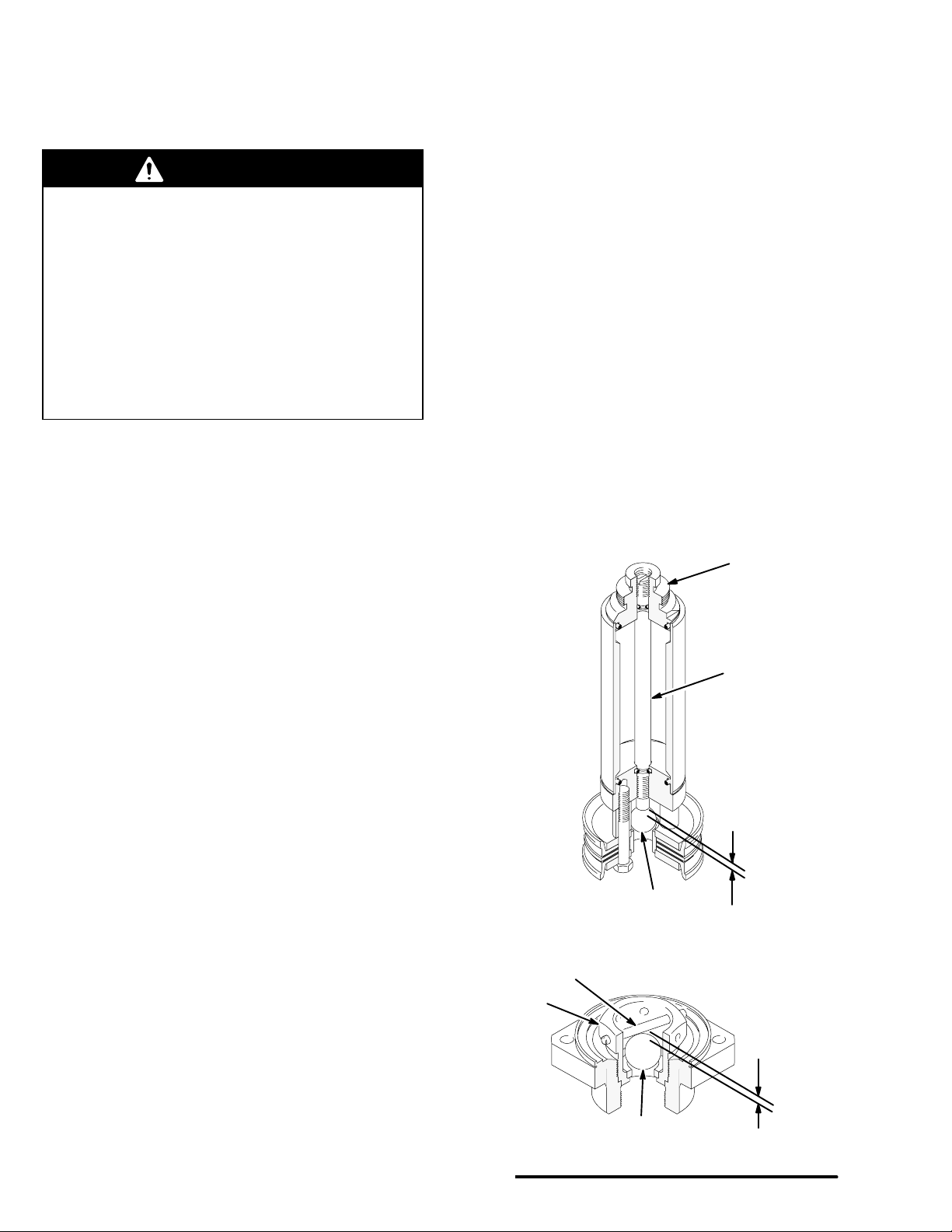
Piston and Intake Valve Adjustment
See Fig. 1. The fluid piston and intake check valves
are factory-set for pumping medium viscosity fluids.
The ball stop pin (18) in the intake valve is in the
lowest set of holes. The piston ball travel is set at
0.204 in. (5.2 mm), measured from the end of the
adjustable plunger rod (23) to the top of the ball (22).
This distance represents four complete turns of the rod
(23) from the top of the ball.
4 307983
Fig. 1
16
18
22
Piston Valve
15
Intake Valve
23
Ball Travel
Ball Travel
06081
Page 5

Service
Before you start:
1. Have all necessary repair parts on hand. Recommended spare parts are marked in the parts list
with a check mark, for example (3n).
2. Packing Repair Kits are available for some pumps.
See the parts list for your pump to order the correct kit. Use all the new parts in the kit for the best
results. Kit parts are indicated in the parts list with
an asterisk, for example (5*).
3. Always replace the glands when replacing the
packings, whether or not you use a repair kit.
4. Use a compatible solvent to clean parts. Inspect
for wear or damage and replace parts as needed.
5. Use light, waterproof grease wherever lubrication
is recommended.
Disassembly (See Fig. 2)
WARNING
To reduce the risk of serious injury whenever you
are instructed to relieve pressure, always follow the
Pressure Relief Procedure on page 4.
1. Flush the pump, if possible. Relieve the pressure.
2. Disconnect the air and fluid lines. Remove the
pump from its mounting and clamp it in a vise.
Disconnect the displacement pump from the motor
as explained in your separate pump manual.
3. Loosen the packing nut/wet-cup (1). Unscrew and
remove the four tie bolts (30) and lockwashers
(31). Pull the intake valve housing (14) off the
pump.
4. Remove and inspect the intake valve gasket (17).
Unscrew the retainer and seat assembly (16) from
the intake valve housing (14). Remove the ball
stop pin (18), noting which holes it is in. Remove
the intake valve ball (15). Handle the ball carefully
as it can be easily damaged.
5. Clean all parts of the intake valve and inspect
carefully for wear or damage. Inspect the seat (C)
of the retainer and seat assembly (16), but do not
attempt to remove it. If the seat is worn or damaged, replace the entire retainer and seat assembly.
6. Pull the pump cylinder (9) straight off the outlet
housing (24), being careful not to tilt it until it is
clear of the displacement rod (8) and piston assembly (B).
7. Inspect the polished inner surface of the cylinder
(9) for scoring, wear or damage by running a finger
over the surface or holding the part up to a light at
an angle. Replace if necessary.
8. Remove the three screws (19) and washers (20),
and disassemble the piston. Be very careful when
handling the ball (22) and seat (13) as they can be
very easily damaged. Clean all parts and inspect
carefully for wear or damage. See Fig. 4.
9. Unscrew the packing nut/wet-cup (1) from the
outlet housing (24). Pull the displacement rod (8)
down out of the outlet housing. Remove and
inspect the outlet housing gasket (7).
10. Push the throat packings and glands (A) out of the
outlet housing (24). Clean the outlet housing and
throat packings, and inspect for wear or damage.
11. Inspect the polished outer surface of the displacement rod (8) for scoring, wear or damage by
running a finger over the surface or holding the
part up to a light at an angle. Replace if necessary.
12. Do not disassemble the displacement rod
assembly unless necessary. Before disassembling, carefully measure how far the adjustable
plunger rod (23) protrudes from the lower cap (10).
This determines the amount of piston ball (22)
travel. Screw the plunger rod (23) out of the displacement rod assembly, and inspect the o-rings
(3) in place. Disassemble the upper and lower
caps (27, 10) from the displacement rod (8).
Inspect the o-rings (4) in place.
307983 5
Page 6

1
See Fig. 3.
2
See Fig. 4.
Apply thread sealant.
3
Lubricate threads and torque to
4
20–24 ft–lb (27–33 N.m).
24
Service
1
27
3
4
23
A
7*
8
3
4
1
4
30
4
10
22
9
16
3
2
B
18
14
Fig. 2
6 307983
15
17*
C
06082
Page 7

Service
Reassembly (See Fig. 2)
1. Lubricate the packing nut threads and all packings
and seals with silicone-free lubricant, such as no. 2
lithium-base grease, before reassembling.
2. If it was necessary to disassemble the displacement rod assembly, reassemble the upper and
lower caps (27, 10) and the plunger rod (23) to the
displacement rod (8). Screw the plunger rod
through the lower cap until it protrudes the required distance as was recorded in step 12 of
Disassembly.
1
Apply sealant to male threads and torque to 80–90 ft–lb (108–122 N.m).
2
Lips of v-packings must face down.
3
Lubricate threads and torque to 20–24 ft–lb (27–33 N.m).
4
Lubricate.
3. Install the male gland, v-packings, and female
gland in the outlet housing (24), as shown for your
pump model (see Fig. 3). Install the v-packings
one at a time, with the lips facing down.
4. Install the gasket (7*) in the outlet housing (24).
Loosely install the packing nut/wet-cup (1). Insert
the displacement rod assembly in the bottom of
the outlet housing and push it up until the threads
of the upper cap (27) are roughly level with the top
of the packing nut/wet-cup. (This makes it easier
to connect the coupling nut when the displacement
pump is reinstalled on the motor.)
Fig. 3
*26
2
*25
29
1
1
3
4
5*
4
2
6*
24
06083
307983 7
Page 8

Service
5. Place a washer (20) on each of the three screws
(19). Assemble the piston as shown for your pump
model (see Fig. 4). Place the piston valve seat
(13) in the center of the piston assembly so its lip
bottoms out. Continue stacking the parts on the
screws (19) as shown. Place the piston ball (22)
on the seat (13).
6. Place a piston spacer (42) on each of the screws
(19). Apply thread sealant to the screws and screw
the piston assembly into the lower cap (10).
Torque the screws (19) to 240–300 in-lb (27–34
N.m). See Fig. 4.
7. Carefully guide the cylinder (9) over the piston
assembly and displacement rod until it seats in the
outlet housing (24). See Fig. 2.
8. Apply thread sealant and screw the retainer and
seat assembly (16) into the intake valve housing
(14). Install the gasket (17*) on the intake valve
housing.
9. Place the intake valve ball (15) on the seat of the
retainer and seat assembly (16). Install the ball
stop pin (18) in the same set of holes from which it
was removed. (To readjust ball travel, see Piston
and Intake Valve Adjustment on page 4.)
10. Lubricate the tie bolts (30) and install a lockwasher
(31) on each. Install the tie bolts through the intake
valve housing (14) and up into the outlet housing
(24). Torque oppositely and evenly to 20–24 ft-lb
(27–33 N.m).
11. Torque the packing nut/wet-cup (1) 20–24 ft-lb
(27–33 N.m); do not overtighten or you may damage the packings. Reconnect the displacement
pump to the motor as explained in your separate
pump manual. Reconnect the ground wire if it was
disconnected during service.
12. Fill the packing nut/wet-cup (1) 1/2 full of Graco
Throat Seal Liquid or a compatible solvent. Reconnect all hoses and return the pump to operation.
1
Apply thread sealant and torque to 240–300 in–lb (27–34 N.m).
42
22n
21n
39*
11*
12n
13
11*
39*
21n
20
Fig. 4
8 307983
19
1
06076
Page 9

Model 223177, Series D
UHMWPE and Leather Packed
Parts
Ref Part
No. No. Description Qty
1 180949 PACKING NUT/WET-CUP 1
3n 106555 O-RING; fluoroelastomer 2
4n 108832 O-RING; fluoroelastomer 2
5* 166489 V-PACKING; leather 2
6* 185662 GLAND, male 1
7* 171168 GASKET; nylon 1
8 185650 ROD, displacement 1
9 24C503 CYLINDER, pump 1
10 161743 CAP, rod, lower 1
11* 185630 PACKING, cup; UHMWPE 2
12n 160019 WASHER, back-up 1
13 180944 SEAT, piston valve 1
14 180930 HOUSING, intake valve 1
15n 101178 BALL, intake; steel;
1–1/4” (31.8 mm) diameter 1
16 205061 RETAINER and SEAT, intake valve 1
17* 171177 GASKET; nylon 1
18 160006 PIN, straight 1
19 101529 SCREW, hex hd;
3/8–16 x 2–3/4” (70 mm) long;
w/nylon locking patch 3
20 171163 WASHER, flat 3
21n 185964 WASHER, piston 2
Ref Part
No. No. Description Qty
22n 100279 BALL, piston; steel;
7/8” (22 mm) diameter 1
23 185651 ROD, plunger, adjustable 1
24 180932 HOUSING, outlet, pump 1
25* 185647 V-PACKING; UHMWPE 3
26* 185648 GLAND, female 1
27 190067 CAP, rod, upper 1
29 190176 UNION, adapter, straight;
1” npt(m) x 1” npsm(f) swivel 1
30 110349 BOLT, hex hd; 3/8–16 unc–2a x
9” (229 mm) long 4
31 100133 LOCKWASHER; 3/8” (10 mm) size 4
39* 185917 GASKET, piston; cellulose fiber 2
40Y 172479 TAG, warning (not shown) 1
42 160016 SPACER, piston 3
44Y 179761 TAG, warning (not shown) 1
* These parts are included in Repair Kit 223320, which may
be purchased separately.
n Keep these spare parts on hand to reduce down time.
Y Replacement Danger and Warning labels, tags and cards
are available at no cost.
29
*26
*25
24
*7
*17
42
1
22n
21n
27
4n
5*
8
6*
3n
39*
11*
12n
13
11*
39*
23
21n
20
n3
n4
9
10
18
19
15n
16
14
31
30
307983 9
06076
Page 10

Conversion Kit
223321 CONVERSION KIT
(Must be purchased separately)
Converts the pump to PTFE throat packings.
Part No. Description Qty
185648 Female Gland 1
185662 Male Gland 1
166165 V-Packing; PTFE 5
185630 Cup Packing; UHMWPE 2
171168 Gasket; nylon 1
171177 Gasket; nylon 1
185917 Gasket; cellulose fiber 2
10 307983
Page 11

Technical Data
Category Data
Maximum Working Pressure 400 psi (28 bar)
Wetted Parts: Ductile Iron; Carbon Steel; 17–4 PH and 304 Stainless Steel; Cadmium, Zinc,
and Nickel Plating; Nitralloy; fluoroelastomer; Cellulose Fiber; Leather;
Ultra-High Molecular Weight Polyethylene
307983 11
Page 12

Graco Standard Warranty
Graco warrants all equipment manufactured by Graco and bearing its name to be free from defects in material and workmanship on the
date of sale to the original purchaser for use. With the exception of any special, extended, or limited warranty published by Graco,
Graco will, for a period of twelve months from the date of sale, repair or replace any part of the equipment determined by Graco to be
defective. This warranty applies only when the equipment is installed, operated and maintained in accordance with Graco’s written
recommendations.
This warranty does not cover, and Graco shall not be liable for general wear and tear, or any malfunction, damage or wear caused by
faulty installation, misapplication, abrasion, corrosion, inadequate or improper maintenance, negligence, accident, tampering, or substitution of non–Graco component parts. Nor shall Graco be liable for malfunction, damage or wear caused by the incompatibility of
Graco equipment with structures, accessories, equipment or materials not supplied by Graco, or the improper design, manufacture,
installation, operation or maintenance of structures, accessories, equipment or materials not supplied by Graco.
This warranty is conditioned upon the prepaid return of the equipment claimed to be defective to an authorized Graco distributor for
verification of the claimed defect. If the claimed defect is verified, Graco will repair or replace free of charge any defective parts. The
equipment will be returned to the original purchaser transportation prepaid. If inspection of the equipment does not disclose any defect
in material or workmanship, repairs will be made at a reasonable charge, which charges may include the costs of parts, labor, and
transportation.
THIS WARRANTY IS EXCLUSIVE, AND IS IN LIEU OF ANY OTHER WARRANTIES, EXPRESS OR IMPLIED, INCLUDING BUT
NOT LIMITED TO WARRANTY OF MERCHANTABILITY OR WARRANTY OF FITNESS FOR A PARTICULAR PURPOSE.
Graco’s sole obligation and buyer’s sole remedy for any breach of warranty shall be as set forth above. The buyer agrees that no other
remedy (including, but not limited to, incidental or consequential damages for lost profits, lost sales, injury to person or property, or any
other incidental or consequential loss) shall be available. Any action for breach of warranty must be brought within two (2) years of the
date of sale.
Graco makes no warranty, and disclaims all implied warranties of merchantability and fitness for a particular purpose in connection
with accessories, equipment, materials or components sold but not manufactured by Graco. These items sold, but not manufactured
by Graco (such as electric motors, switches, hose, etc.), are subject to the warranty, if any, of their manufacturer. Graco will provide
purchaser with reasonable assistance in making any claim for breach of these warranties.
In no event will Graco be liable for indirect, incidental, special or consequential damages resulting from Graco supplying equipment
hereunder, or the furnishing, performance, or use of any products or other goods sold hereto, whether due to a breach of contract,
breach of warranty, the negligence of Graco, or otherwise.
FOR GRACO CANADA CUSTOMERS
The parties acknowledge that they have required that the present document, as well as all documents, notices and legal proceedings
entered into, given or instituted pursuant hereto or relating directly or indirectly hereto, be drawn up in English. Les parties reconnaissent avoir convenu que la rédaction du présente document sera en Anglais, ainsi que tous documents, avis et procédures judiciaires
exécutés, donnés ou intentés à la suite de ou en rapport, directement ou indirectement, avec les procedures concernées.
Graco Information
For the latest information about Graco products, visit www.graco.com.
TO PLACE AN ORDER, contact your Graco distributor, or call one of the following numbers
to identify the distributor closest to you:
1–800–328–0211 Toll Free
612–623–6921
612–378–3505 Fax
All written and visual data contained in this document reflects the latest product information available at the time of publication.
Graco reserves the right to make changes at any time without notice.
12 307983
This manual contains English. MM 307983
Graco Headquarters: Minneapolis
International Offices: Belgium, China, Japan, Korea
GRACO INC. P.O. BOX 1441 MINNEAPOLIS, MN 55440–1441
Copyright 1989, Graco Inc. is registered to ISO 9001
www.graco.com
Revised 07/2009
 Loading...